
Related Manuals for MICRO-EPSILON turboSPEED DZ140


Summary of Contents for MICRO-EPSILON turboSPEED DZ140
- Page 1 Operating Instructions turboSPEED DZ140 DS05(03) DS05(04) DS1(04) DS05(07) DS1/T DS05(14) DS05(15)
- Page 2 Speed measuring system for turbo chargers MICRO-EPSILON MESSTECHNIK GmbH & Co. KG Königbacher Strasse 15 94496 Ortenburg / Germany Tel. +49 (0) 8542 / 168-0 Fax +49 (0) 8542 / 168-90 e-mail info@micro-epsilon.de www.micro-epsilon.com...
-
Page 3: Table Of Contents
Sensor ................................12 Sensor Cable ..............................15 Supply and Signal Cable ..........................15 Controller DZ140............................16 Electrical Connections ........................... 17 4.5.1 Supply, Outputs ..........................17 4.5.2 Power Supply ..........................18 4.5.3 RAW SIGNAL ..........................20 4.5.4 Ground Concept ........................... 20 turboSPEED DZ140... - Page 4 Number of Blades......................... 27 Analog Output ............................... 28 Troubleshooting ............................29 Liability for Material Defects ........................31 Service, Repair ............................31 Decommissioning, Disposal ......................... 31 Appendix Optional Accessories ..........................32 Labels on Rear Side of Controller for Printing..................33 turboSPEED DZ140...
-
Page 5: Safety
> Damage to or destruction of the sensor and / or controller Avoid shocks and impacts to the sensor and controller. NOTICE > Damage to or destruction of the sensor and controller Protect the sensor cable against damage > Failure of the measuring device turboSPEED DZ140 Page 5... -
Page 6: Notes On Ce Marking
Safety Notes on CE Marking The following apply to the turboSPEED DZ140: - EU directive 2014/30/EU - EU directive 2011/65/EU, “RoHS” category 9 Products which carry the CE mark satisfy the requirements of the EU directives cited and the European harmonized standards (EN) listed therein. -
Page 7: Proper Environment
5 - 95 % (non-condensing) - Ambient pressure: Atmospheric pressure - Supply: 9 ... 30 VDC / briefly 36 VDC / max. 50 mA If power supply is higher, the max. acceptable ambient temperature decreases, see Fig. turboSPEED DZ140 Page 7... -
Page 8: Functional Principle, Technical Data
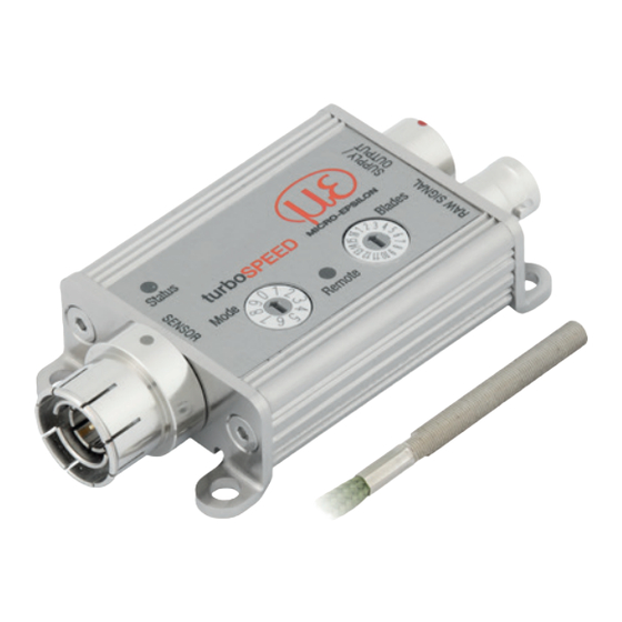
- Controller (installed in a compact aluminum housing) - Power supply and signal cable, see Chap. Individual components of the measuring system can be changed without limiting the functionality. Sensor Controller Status turboSPEED Mode Blades Remote Fig. 1 Components for speed measurement turboSPEED DZ140 Page 8... -
Page 9: Technical Data
0 ... 5 V (-50 ... +300 °C, -58 ... +572 °F) Power supply 9 V ... 30 VDC / max. 50 mA (short-term up to 36 VDC) If power supply is higher, the max. acceptable ambient temperature decreases, see Fig. turboSPEED DZ140 Page 9... - Page 10 PC140-3 supply and output cable 3 m Cable PC140-6 supply and output cable 6 m PC140-8 supply and output cable 8 m Weight Controller DZ140: appr. 92 g Protection class Controller DZ140: IP 65 FSO = Full Scale Output turboSPEED DZ140 Page 10...
-
Page 11: Delivery
You will find further optional accessories in appendix, see Chap. Storage - Storage temperature: ƒ Sensor and sensor cable: -40 ... +200 °C (-40 ... +392 °F) ƒ Controller: -40 ... +125 °C (-40 ... +257 °F) - Humidity: 5 - 95 % (non-condensing) turboSPEED DZ140 Page 11... -
Page 12: Installation
BNC connector 45° ±3° 35 (1.38) Fig. 2 Dimensional drawing DS05(03) Sensor cable ø approx. 3.5 mm appr. 9,5 (2.60) Length 0.5 m (±0.15 m) (0.37) with BNC connector Fig. 3 Dimensional drawing DS05(04) Measuring direction turboSPEED DZ140 Page 12... - Page 13 Length 0.5 m (±0.15 m) with BNC connector appr. 9,5 (1.10) (0.37) Fig. 5 Dimensional drawing DS05(14 Sensor cable ø approx. 3.5 mm Length 0.5 m (±0.15 m) with BNC connector appr. 9,5 (0.37) (1.77) Fig. 6 Dimensional drawing DS05(15) turboSPEED DZ140 Page 13...
- Page 14 Sensor cable with metal protec- tion hose stainless steel IP 40 (1.65) ø appr. 6.0; cable length 0.8 m (± 0.15 m) with BNC-connector Fig. 9 Dimensional drawing DS1(04) Dimensions in mm (inches), not to scale Measuring direction turboSPEED DZ140 Page 14...
-
Page 15: Sensor Cable
Supply and Signal Cable Never come below the proper bending radius of the supply and signal cable: 7.5 x cable outer diameter. Fig. 10 Supply and signal cable, 3, 6 or 8 m long turboSPEED DZ140 Page 15... -
Page 16: Controller Dz140
Controller DZ140 The controller DZ140 is installed in an aluminum housing. The controller demodulates and amplifies the speed-dependent measuring signal. 41.3 83.8 (1.63) (3.3) (2.44) Fig. 11 Dimensions controller, dimensions in mm (inches), not to scale turboSPEED DZ140 Page 16... -
Page 17: Electrical Connections
An interior shielding braid (Pin 5) meshs the signals Pin 1 and the signal on Pin 3. PC140-x is a 3, 6 or 8 m long, pre-assembled 8-wired power and signal cable. It must be ordered as the sensor separately. The out- puts are temporary short-circuit proof. Pin 9 and 10 are not assigned. turboSPEED DZ140 Page 17... -
Page 18: Power Supply
The controller is protected against voltage reversal and overvoltage. Only use the power supply for measuring devices and not simultaneously for drives or similar pulse interference. MICRO-EPSILON recommends the power supply unit PS2020, see Chap. 1. 12 V on- board power supply is possible. - Page 19 R Wire Fig. 16 Short connection leads directly to the supply - recommendation Also consider the possible ground loops, which can result from the use of the multi corrugated spring (connection between GND and PE), see Chap. turboSPEED DZ140 Page 19...
-
Page 20: Raw Signal
Disconnect the connected measuring devices after alignment of the sensor distance and close the female connector with the delivered protection cap. 4.5.4 Ground Concept Supply + Supply - Sensor Triax Shield DZ140 Controller Fig. 17 Ground concept for DSx sensors turboSPEED DZ140 Page 20... - Page 21 Installation Supply + Supply - Sensor Shield Triax DZ140 Controller Fig. 18 Ground concept for DSx/T sensors turboSPEED DZ140 Page 21...
-
Page 22: Operation
After applying the supply voltage, the controller initializes. It is shown by means of fast red-yellow-green Status flashing of the LED, see Chap. 5.2. Set the mode and the number of blades, see Chap. 5.5.1, see Chap. 5.5.2. Make sensor positioning, see Chap. 5.3. turboSPEED DZ140 Page 22... -
Page 23: Leds On The Controller
Status red, yellow, green Initialization No sensor red, flashes Teach to sensor Status (1 sec. Takt) turboSPEED red, Error Mode Blades flashes quickly yellow Controller ready Remote green Blade detected green, flares Mode 8 (test pulse) turboSPEED DZ140 Page 23... -
Page 24: Positioning Of The Sensor
2V/DIV; RAW SIGNAL: CH II, 1V/DIV; TB: 2 ms/DIV; trigger: CH I CH II CH II CH II CH I CH I CH I LED status: shines yellow LED status: shines green LED Status: shines green turboSPEED DZ140 Page 24... -
Page 25: Test Signal
1666.7 Hz. Fig. 19 Settings for the test signal The temperature signal is output independently from the test signal. If no sensor is connected, no tem- perature signal is output (respectively 5 VDC). turboSPEED DZ140 Page 25... -
Page 26: Settings
- Mode 3: 200k med (200.000 rpm, medium sensitivity) - Mode 4: 400k low (400.000 rpm, low sensitivity) - Mode 5: 200k low (200.000 rpm, low sensitivity) - Mode 8: test signal, see Chap. Fig. 21 Rotary switch for speed, sensitivity and test mode turboSPEED DZ140 Page 26... -
Page 27: Number Of Blades
Operation The list of modes is fixed as a quick guide on the back side of the turboSPEED DZ140 and can be also printed separately if it is covered during the measurement, see Chap. 5.5.2 Number of Blades Set the number of blades of the turbo charger using the switch... -
Page 28: Analog Output
- Range 0 ... +5 V - Linear, depends on rotation speed Mode 1, 3, 5 Mode 0, 2, 4 200,000 400,000 100,000 200,000 Fig. 23 Analog signal for max. 200,000 rpm Fig. 24 Analog signal fo max. 400,000 rpm turboSPEED DZ140 Page 28... -
Page 29: Troubleshooting
Fig. Note that the spring ring rests entire surface on both sides. First remove any contamination on the contact surfaces of the fire ring (housing, BNC plug, etc.) NOTICE > Bad connection between GND and PE turboSPEED DZ140 Page 29... - Page 30 (PE) are connected together by the spring ring. > Unwanted ground loops The improved shielding of the Triax line against a coaxial line can be impaired. Multi corrugated spring ring Fig. 27 Side view controller turboSPEED with multi cor- rugated spring ring turboSPEED DZ140 Page 30...
-
Page 31: Liability For Material Defects
Within this period, defective parts, except for wearing parts, will be repaired or replaced free of charge, if the device is returned to MICRO-EPSILON with shipping costs prepaid. Any damage that is caused by improper handling, the use of force or by repairs or modifications by third parties is not covered by the liability for mate- rial defects. -
Page 32: Appendix
Optional Accessories PS2020 Power supply unit for mounting on DIN-rail, Input 230 VAC, Output 24 VDC/2.5 A DD241PC(11)-U Digital process display, Display of a selected measuring value, Connection to the analog output 0 - 10 V turboSPEED DZ140 Page 32... -
Page 33: A 2 Labels On Rear Side Of Controller For Printing
Labels on Rear Side of Controller for Printing The list of modes, see Chap. 5.5.1, is fixed as a quick guide on the back side of the turboSPEED DZ140. Fig. 28 Label - big Fig. 29 Sticker - small turboSPEED DZ140 Page 33... - Page 34 MICRO-EPSILON MESSTECHNIK GmbH & Co. KG X9751314-A071069HDR Königbacher Str. 15 · 94496 Ortenburg / Germany MICRO-EPSILON MESSTECHNIK Tel. +49 (0) 8542 / 168-0 · Fax +49 (0) 8542 / 168-90 *X9751314-A07* info@micro-epsilon.de · www.micro-epsilon.com...
Need help?
Do you have a question about the turboSPEED DZ140 and is the answer not in the manual?
Questions and answers