Table of Contents
Advertisement
DSMX-Compatible 7-Channel Integrated Telemetry Receivers
Contents
Introduction . ........................................................................................................................................ 1
Overview of the LM0051/52 . ................................................................................................................... 1
PART 1: Essential Instructions .............................................................................................................. 5
A. Basic Requirements ............................................................................................................................. 5
B. Binding the Receiver . ........................................................................................................................... 5
C. Installation ........................................................................................................................................... 6
D. Testing ................................................................................................................................................. 7
E. Failsafe ................................................................................................................................................. 7
F. Telemetry . ............................................................................................................................................ 8
G. Connecting Servos . ............................................................................................................................ 11
PART 2. Information for Advanced Users . ........................................................................................... 11
A. RSSI (Signal Strength) ........................................................................................................................ 11
B. Antennas and Satellites ..................................................................................................................... 12
C. Power Consumption and Voltage ...................................................................................................... 13
D. Creating and Reading Telemetry Log Files ........................................................................................ 13
Annex A: Calibrating Voltage and Current .......................................................................................... 15
1. Recalibrating the Receiver for the Optional V/I Sensor . .................................................................... 15
2. Voltage Recalibration with the Sensing Wire .................................................................................... 17
Annex B: Using a Non-Spektrum Transmitter ..................................................................................... 20
1. Setting up Lemon telemetry using OpenTX Firmware . ...................................................................... 20
2. Setting up Lemon telemetry using ErSky9x Firmware ....................................................................... 22
Annex C: Servo Output Timing ........................................................................................................... 23
Instructions
for the
Lemon Rx LM0051 and LM0052
Version 1.0
Advertisement
Table of Contents

Related Manuals for Lemon Rx LM0051


Summary of Contents for Lemon Rx LM0051
-
Page 1: Table Of Contents
Version 1.0 Instructions for the Lemon Rx LM0051 and LM0052 DSMX-Compatible 7-Channel Integrated Telemetry Receivers Contents Introduction ............................1 Overview of the LM0051/52 ........................1 PART 1: Essential Instructions ......................5 A. Basic Requirements ..........................5 B. Binding the Receiver ..........................5 C. Installation ............................6 D. Testing ..............................7 E. Failsafe ..............................7 F. Telemetry ............................. 8 G. Connecting Servos ..........................11 PART 2. Information for Advanced Users .................... 11 A. RSSI (Signal Strength) ........................11 B. Antennas and Satellites ........................12 C. Power Consumption and Voltage ...................... 13 D. Creating and Reading Telemetry Log Files ..................13 Annex A: Calibrating Voltage and Current ..................15 1. Recalibrating the Receiver for the Optional V/I Sensor ..............15 2. Voltage Recalibration with the Sensing Wire ..................17 Annex B: Using a Non-Spektrum Transmitter ..................20 1. Setting up Lemon telemetry using OpenTX Firmware ............... 20 2. Setting up Lemon telemetry using ErSky9x Firmware ............... 22... -
Page 2: Introduction
The LM0051 sends back real time data to the transmitter on receiver voltage, temperature and RSSI (signal strength), and, with the included V/I external sensor, provides voltage, current and remaining capacity readings for the flight pack of an electric powered model. The LM0052 does all this and also provides altitude and vertical speed (vario) data from a built-in barometric sensor. Note that there are also “U” versions of both receivers that do not include the V/I sensor; they can be ordered from Lemon Rx as a separate item at a later date, but then require calibration by the user. The various parameters of telemetered data are displayed on the transmitter screen and can trigger audio tones or haptic alarms. Data values and alarms can be spoken by voice-enabled transmitters, including most second generation and above Spektrum units, as well as the FrSky Taranis/Horus, Turnigy 9XR Pro and others. The spoken read-out is virtually essential to take full advantage of telemetry, which becomes a significant distraction if it requires the pilot to look away from the aircraft while flying. Throughout these notes, the two telemetry receivers will be referred to collectively as LM0051/52, except when discussing the altitude and vario features found only in the LM0052. This manual is organized as follows: Part 1: Essential Instructions provides all the information most people will require to use the LM0051/52 with a compatible Spektrum transmitter. Part 2: Information for Advanced Users supplies additional material that some users may need. Annex A: Voltage and Current Calibration explains how to reset the receiver to a V/I sensor. Annex B: Transmitters other than Spektrum covers the use of Lemon telemetry equipment with OpenTX or ErSky9x firmware in transmitters such as the FrSky Taranis and Turnigy 9XR Pro. Annex C: Servo Output Timing explains the sequence in which control pulses are sent to the servos. Overview of the LM0051/52 Performance Both the radio control receiver and the telemetry transmission functions of the Lemon LM0051/52 • give exceptionally good range, operating to the normal limits of unaided visual flight and beyond. This is achieved by using efficient circuit design, as well as dual antennas and antenna switching to ensure maximum signal reliability in both directions. The low noise amplifier (LNA) in the receiver front end ensures maximum sensitivity to detect weak • radio frequency signals. Users should experience a noticeable improvement in range compared to most other DSM2 and DSMX receivers and compatibles. Independent testing has shown this receiver to have significantly more range in a standard reduced power range test than several other comparable receivers tested under identical conditions. Performance of the LM0051/52, particularly telemetry, has been improved over the earlier LM0041 telemetry receiver. -
Page 3: Compatible Transmitters
Instructions for the Lemon Rx LM0051 and LM0052 Telemetry Receivers The unit has dual diversity antennas of the extended type for versatile placement in many types of • application, including use in models with carbon fiber components. The active receiving/transmitting element is the last 32mm of the antenna cable, which has semi-transparent silver/white PVC shielding. In addition, a DSMX satellite receiver can be attached to the LM0051/52 to enhance signal security. • Satellites with and without diversity switched antennas are available from Lemon Rx. Compatible Transmitters Telemetry from the LM0051/52 can both be displayed on-screen and spoken by recent Spektrum • telemetry-enabled transmitters: DX6G2/3, DX7G2, DX8G2, DX9 (all versions), DX10t, DX18 (all versions except the first), and DX18t. The new iX12 transmitter is fully telemetry-enabled. The current DX6e, as well as the older first generation DX8 and the original DX18, can display • telemetry data on-screen and have some limited alert beeps and vibration, but lack voice capability and therefore cannot speak alarms. Older Spektrum radios, such as the original DX7 and the DX6i have no telemetry functionality, and • neither do such JR radios as the X9503. A general summary of the telemetry capability of Spektrum transmitters can be seen in this table: • https://www.spektrumrc.com/ProdInfo/Files/SPM_Telemetry_Compatibility.pdf The LM0051/52 also operates successfully with the Multimodule 4in1 add-on transmitter module • for the FrSky Taranis, Turnigy 9XRPro and other transmitters that accept a “JR” format external RF module. Both OpenTX and FrSky9x firmware support telemetry, though only in some versions of the firmware. The telemetry setup is somewhat different with such transmitters. See Annex B. Telemetry Built-in sensors in the LM0051/52 provide receiver voltage, internal temperature and RSSI (signal • strength). In addition, the LM0052 also includes a precision barometer that reports altitude and vertical speed (vario). The included external sensor wires measure flight pack battery voltage (when connected to the • positive side of the battery) and give a more accurate external temperature reading that automatically replaces the default internal value. The LM0051 and LM0052 include a voltage/current (V/I) sensor that measures up to 30V and 60A. - Page 4 Instructions for the Lemon Rx LM0051 and LM0052 Telemetry Receivers RSSIout for support of an on-screen display (OSD) is also available from the receiver in the form of • an analog voltage ranging from 3V (=100%) down to 0V. This can be accessed by using the third wire in the supplied external temperature lead. No separate airborne telemetry unit is required with this receiver. Nor can such a unit, Lemon or • other, be connected, as the second data stream would interfere with that of the integrated receiver. Failsafe The LM0051/52 offers a choice of three types of failsafe: • No Pulse: If no action is taken to set failsafe, the unit defaults to emitting no pulses on loss of signal. On an electric model, this normally results in the motor stopping after a couple of seconds. Servos will tend to stay where they are but are not locked into position. The green LED is OFF. All-channel Preset: Pressing the Failsafe button briefly while the receiver is in bind mode selects a failsafe mode in which, on loss of signal, all channels go to the position they were at when the button was pushed. The green LED is solidly ON. Throttle-only Preset: A second brief press on the button gives a failsafe mode in which only the throttle goes to the position it was at when the button was pushed; all other channels hold their current position. The green LED is FLASHING. LED Receiver Status Indicators There are three lights in the receiver: • RED: Solid – successful bind RF link to transmitter; Flashing Rapidly – bind mode; GREEN: Off – No Pulse on signal loss; Solid – All-channel Preset failsafe; Flashing Slowly – Throttle-only Preset failsafe; BLUE: Only used for user calibration of V/I sensor. Operation The unit requires a power supply of 4.5V to 8.5V. It is important to note the minimum voltage, • which is higher than required by most Lemon receivers. In particular, this receiver cannot be operated from a single LiPo cell. It can be operated from a 2S LiPo however. The pins labeled Bind/AUX2 do double duty as bind pins and Channel 7 (AUX2) servo output; when a • bind plug is present the receiver shuts down servo output. Thus, the servo can be: (1) connected after binding; or (2) plugged into to one branch of a Y-cable, with the bind plug inserted into the other branch and then removed after binding.
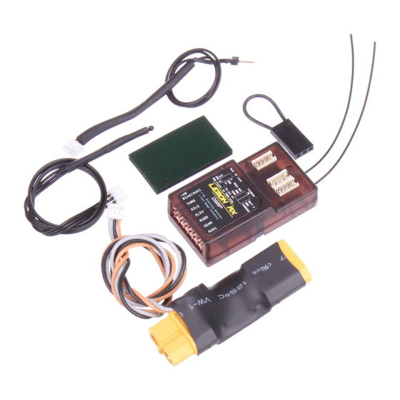
- Page 5 Instructions for the Lemon Rx LM0051 and LM0052 Telemetry Receivers The LM0051U and LM0052U versions do not include the V/I sensor. It is available separately, but when purchased as an add-on, the receiver has to be recalibrated by the user, as explained in Annex A. (The V/I sensor is the same as that used with the LM0041 receiver and LM0030 stand-alone telemetry unit.) Figure 2 shows what the LM0052 receiver looks like without its case and identifies the various connections. Weight without the case is 5.4 g Figure 2: What's in the package (compared to 9.9g with case). The LM0051 is identical, except for the absence of the barometric sensor. The three white connectors for the satellite and the two telemetry leads are identical and when plugged in are not all oriented the same way. Note that the wires are not color-coded. Take special care to follow the labels on the case (Figure 3) when plugging the connectors in. Be especially careful with the voltage sense wire, as connecting the pack voltage to the wrong pin will almost certainly cause damage. The label clearly identifies all the connectors, including their Figure 1: What’s in the Package individual wires. Figure 3: LM0052 Label Figure 2: LM0052 with Case Removed...
-
Page 6: Part 1: Essential Instructions
Instructions for the Lemon Rx LM0051 and LM0052 Telemetry Receivers PART 1: Essential Instructions A. Basic Requirements Transmitter To provide both radio control and telemetry, this receiver requires a Spektrum DSMX telemetry-enabled transmitter or compatible (see current list of suitable Spektrum transmitters on page 2). For use with a non-Spektrum transmitter, such as the FrSky Taranis or Turnigy 9XR Pro, see Annex B. The receiver provides output to the servos at 22mS frame rate, even if the transmitter has been forced into 11mS mode. If the screen shows binding at DSMX 11mS, this only means that the connection from transmitter to receiver is operating at the higher frame rate (giving the advantage of more frequent reception of data packets). The receiver converts the rate down to 22ms when it outputs the information, thus ensuring maximum compatibility with any kind of servo. The LM0051/52 will function as a receiver only (no telemetry) with a wide range of other Spektrum transmitters and modules, including older DSM2 units, as well as with various compatible transmitters and modules. With a DSM2 transmitter, or a DSMX transmitter in DSM2 mode, the receiver will automatically switch to DSM2 when it detects the bind signal. Power Supply This receiver requires a higher minimum voltage power supply than most other Lemon receivers, although it will recover well from brief low voltage brownouts. Ensure that under load your BEC or receiver battery does not fall below the 4.5V minimum at any time. Be aware that some cheap “3A” BECs, especially those integrated into ESCs, are optimistically rated and can easily be overloaded by multiple servos and other high drain devices such as are found in some modern park flier size “Ready to Fly” aircraft equipped with retracts, flaps, lights, sound systems, etc. Some 4.8V NiMH receiver packs also have limited current capability and may drop voltage significantly under load; be sure to use cells that can deliver adequate current for the load placed on them. See Annex C for a discussion of how the receiver outputs information to the servos and the possible implications of this for power requirements. B. Binding the Receiver Binding requires that the receiver be put into bind mode (red light flashing) and that the transmitter then be powered up in its bind mode (see the transmitter manual for specific instructions). Procedure 1. -
Page 7: Installation
Instructions for the Lemon Rx LM0051 and LM0052 Telemetry Receivers unless the light is flashing correctly. 3. Turn on the transmitter in bind mode approximately 2 meters away from receiver. The receiver LED should change to slowly flashing, then to steady RED indicating successful bind (see Figure 5). If you don’t get a solid red light on the receiver (and satellite if used), see the advice below. 4. For default operation of the receiver, remove the power and bind plug at this point; Figure 5: Solid red light indicates successful bind OR, to set Failsafe leave power connected and bind plug in place (see Section E, below). Binding Problems It is not unusual to encounter difficulties binding DSM-type receivers, with the receiver either continuing to flash rapidly or starting the bind process but never attaining the solid light that indicates a link. Being very sensitive, the Lemon RX Telemetry Receiver may be a little fussier than usual about bind conditions. Bind problems can usually be overcome by simply increasing the distance between transmitter and receiver during bind. Even then, more than one try may be needed to achieve success. For each try, repeat the entire sequence, starting with both receiver and transmitter powered down. If binding fails at 2 meters, start again, moving further away before turning on the transmitter in bind mode, and have your body between the transmitter and receiver to attenuate the signal further. When binding, stay away from metallic objects (such as cars, wire fences and steel tables), as well as damp ground and other conductive surfaces. Wireless routers and other WiFi sources can also inhibit binding. C. Installation The receiver should be installed using normal good practices for 2.4 GHz equipment. Particular attention should be paid to the location and orientation of the active portions of the dual antennas (the last 32mm of the cable, from which the outer sheath has been removed to expose the silver/white inner cable). The two antennas should be routed so as to achieve wide separation and the active portions should be approximately at right angles to each other. Do not align the antennas side-by-side or in line. The active portions of the antennas should be reasonably straight for optimum receiving and transmitting performance, but the rest of the cable can be curved gently as required. The coaxial cable used for antennas is fragile and must not be kinked or allowed to flop around or vibrate excessively. The active portions of the antennas should not be immediately adjacent to conductive items such as wiring, ESC, battery or carbon fiber that could block the signal (note that non-conductive materials like most foam, balsa, ply, etc. pose no problem... -
Page 8: Testing
Instructions for the Lemon Rx LM0051 and LM0052 Telemetry Receivers important to avoid locating the active portions of the antennas where both can be simultaneously blocked by the battery from receiving a good signal. A more comprehensive treatment of these issues can be found Parts 2A and 2B of these Instructions. D. Testing It is important to conduct a rigorous reduced-power range test before the first flight. The model should be placed on a wooden table or similar non-conductive support. Put the transmitter into Range Test mode (see transmitter manual). With the receiver turned on, walk away about 25m (30 paces) and then circle the model while testing control. If there are any angles at which control is reduced or lost, go back and review the installation. If telemetry is functional, the RSSI value should be monitored during the range test; this will help to identify any problems with the installation. There is more information about RSSI in Part 2A. At the beginning of each subsequent flying session, a brief reduced power test at 25m should be done to check that all is working properly. There is no need to repeat the circling of the model. E. Failsafe The receiver will enter failsafe mode whenever it is unable to receive a control signal from its bound transmitter for about one second or more (this should be a very rare event). Once a valid signal is again detected, the receiver will resume transmitter control. Three types of failsafe behavior can be selected for the LM0051/52: No Pulse: If failsafe is not deliberately set, the default action when signal is lost is for the receiver to cut off pulses on all channels. This will cause most modern electric speed controls (ESCs) to shut down the motor within a second or so and will leave servos wherever they happen to be at the moment (but not actively driven by the receiver). In this mode, the green LED on the receiver is OFF. WARNING: The default No-pulse failsafe is unsatisfactory for IC (fuel) powered models, as the engine will continue to run at the power set by the throttle servo when the signal was lost. All-channel Preset failsafe, indicated by the green light solidly ON, provides specific outputs on each of the seven channels in the event of signal loss. Throttle-only Preset failsafe, indicated by the green light FLASHING, sends the throttle to the position it was at when the receiver was bound and failsafe set. All other channels hold their position as it was at the moment of signal loss. The two Preset Failsafe modes are activated as follows: 1. For electric models, remove the propeller(s) or otherwise ensure that the model is safe. 2. Follow the bind steps previously specified (on page 5) from 1 to 4. DO NOT remove the bind plug or power at this point. 3. For All-channel Preset, adjust the sticks, switches, etc. to the desired failsafe outputs. -
Page 9: Telemetry
Instructions for the Lemon Rx LM0051 and LM0052 Telemetry Receivers In either case, for most powered models, the critical requirement is that throttle go to LOW. 4. For All-channel Preset, press the Failsafe button on the receiver briefly ONCE (less than 1 second); the green light should now be solidly ON. For Throttle-only Preset, press the Failsafe button briefly TWICE in quick succession; the green light should now be FLASHING 5. Power off the receiver and remove the bind plug. Failsafe will not work if the plug is still in place. 6. Power up again to test failsafe. Set the throttle to some position above low so the motor is running or the throttle servo is not at low. Turn off the transmitter, wait a short time and verify that the throttle control goes to zero (and for All-channel Preset, other controls go to their set positions). 7. Turn the transmitter back on and verify that transmitter control resumes. Note that if the transmitter is turned off, recovery from failsafe will not occur until the transmitter is again fully operational and linked to the receiver, which may take time (so don’t do this test in the air!). To cancel a Preset Failsafe setting, repeat the process, starting by powering up the receiver in bind mode. Normally, failsafe status and channel settings are retained by the receiver until deliberately reset. However it is possible to change the setting unintentionally while calibrating the V/I sensor (see Annex A). Always check the failsafe setting after such operations. F. Telemetry The following assumes the use of a telemetry-enabled Spektrum transmitter. For non-Spektrum transmitters, see Annex B. For setup of telemetry, the receiver must be bound to the appropriate model in the transmitter and powered up with all sensors connected. Go to Function List or System Setup and choose Telemetry. Fields The following parameters will be normally be displayed, depending on the availability of sensors: Receiver voltage. Automatic, no external sensor or lead required. RSSI – signal strength. Automatic. Displayed on transmitter under parameter “A”. Temperature. Automatic transmission of internal temperature. For maximum accuracy, however, the external temperature sensor provided should be connected. Battery voltage (flight pack). If a V/I sensor is not used, this requires a connection to the battery positive using the voltage sensing wire provided. HINT: To monitor flight pack voltage without modifying the high current power wiring, attach the voltage sensing wire to the most positive pin of the LiPo balance connector. For best telemetry support, make sure you update the transmitter to the latest available Airware version (currently 1.2 for... - Page 10 Instructions for the Lemon Rx LM0051 and LM0052 Telemetry Receivers Battery current (flight pack). Requires that the V/I sensor be inserted into the main power lead. The V/I sensor then replaces the voltage sensing wire and provides both current and voltage information, as well as Flight Pack Capacity (mAh) used. Altitude (LM0052 only). Automatic, no external sensor or lead required. Vertical Speed – commonly called Vario (LM0052 only). Automatic, no external sensor or lead required. Not available on a DX8 Gen1 transmitter. In addition, RSSI is available for use with an OSD (On Screen Display) used with an FPV (First Person View). The RSSIout value is present on the spare wire of the external temperature sensor cable. The analog voltage output varies in proportion to RSSI from 3.0V down to 0V as the signal diminishes. Note that PowerBox fields are not normally required with modern Spektrum transmitters but can be used by the first generation DX8 and DX18 (which do not have a Battery Capacity field). WARNING: Do not plug the voltage sensor cable into the temperature sensor socket! If a battery is attached, doing so is almost certain to damage the receiver. Setup The first item in the Telemetry menu is Auto-Config. In most cases, selecting this will recognize and configure the available parameters, but individual items can be reconfigured separately as required. Auto-Config provides basic setup for on-screen telemetry display. It does not enable the voice and tone signals that are an essential part of using telemetry effectively without the pilot having to look away from the model. To set these, it is necessary to go to the relevant items on the Telemetry page and select how they will be reported. Use the roller to move between the fields and click to select one. You can then choose what is displayed. For example, under most items, the menu allows that particular parameter to be displayed or inhibited, sets minimum and maximum values for purposes of triggering a tone or voice alarm, and determines whether status and warning reports are issued at intervals of 5 to 60 seconds. The Vario item presents a different set of options, in keeping with the audible and graphical nature of the readout; the delay in reporting can be selected from ¼ second to 3 seconds, the on-screen graph can be set to a width of 5 to 60 seconds, and the minimum lift or sink speed to be indicated by audible beeps can be adjusted from 1 to 9.9 m/Sec (3.2 to 32.4 Ft/Sec). On the Telemetry screen is also a Settings item, which leads to a choice of how the telemetry display is selected and whether metric or US units are used. The File Settings item on the Telemetry page allows the filename and method of activation to be set for data logging. The various display fields are generally self-explanatory but there are some differences between Spektrum and Lemon telemetry. In particular the LM0051/52 provides none of the Fade, Frame loss or This sensor is included, factory calibrated, with the LM0051 and LM0052 receivers. It can be purchased separately and added...
- Page 11 Instructions for the Lemon Rx LM0051 and LM0052 Telemetry Receivers Hold information normally found in the Spektrum Flight Log display. Instead Lemon provide a single RSSI number (100->0) in the “A” field that shows received signal strength. Assuming that the V/I sensor is installed in the main power cable, the Telemetry screen will show Flight Pack Volts. The Temperature reading will use the internal sensor unless the external sensor is plugged in, in which case the reading from the sensor at its tip will be displayed: The Flight Pack Capacity screen uses the Current reading from the V/I sensor to measure the usage of battery capacity in terms of milliampere-hours (mAh). The display is set to zero when the receiver is plugged in and counts up as power is consumed. This screen also displays Imax, the maximum current recorded to this point in the flight. The Temperature fields on this screen are not used by Lemon telemetry. A further screen labeled Telemetry provides Altitude (in m or ft) and flight pack current (in Amps). The Vario display presents a graphic readout of Vertical Speed over a chosen period of time. It also includes an Altitude number, the value of which may differ slightly from that displayed on the Altitude/Amps screen. This is of no practical significance and either value may be used. The altitude automatically resets to zero when power is applied, but due to atmospheric fluctuation a small negative value for Altitude is often displayed while on the ground. The Min/Max screen gives a summary of values recorded during the flight. For technical details, see “Why you may get two slightly different altitude values”, page 20. On some Spektrum transmitters the reading may just fluctuate around zero – if so use the main Altitude field.
-
Page 12: Connecting Servos
Instructions for the Lemon Rx LM0051 and LM0052 Telemetry Receivers G. Connecting Servos The receiver outputs standard PWM (Pulse Width Modulation) servo signals, with the signal for each channel available at the corresponding pin, as marked on the case. This allows servos to be plugged directly into the receiver in the usual way. The LM0051/52 operates at 22ms frame rate and can drive both analog and digital servos. Channel 7 (Aux2 in Spektrum terms) pins do double duty as bind pins and servo output pins. Unlike the older LM0041, the LM0051/52 does not have the option of a PPM output. PART 2. Information for Advanced Users A. RSSI (Signal Strength) The RSSI (Received Signal Strength Indicator) number is sent back from the model by telemetry and displayed in the “A” field on the transmitter screen. It represents the strength of the radio control signal available from the receiver front end for control of the model. It should read close to 100 when the transmitter is next to the model and will drop with distance until, at a value typically around 20-30, the telemetry signal is no longer strong enough to convey the data and the display freezes. The telemetry range of the LM0051/52 is significantly better than the earlier LM0041. The receiver has excellent sensitivity and will continue to provide reliable control operate well beyond this point. The vertical bar symbol in the top left shows that telemetry is live and is being received. Depending on the transmitter and Spektrum software the number of bars may give an indication of the telemetry signal strength. While RSSI values below about 20 are unlikely to be seen on the transmitter telemetry screen, the RSSI voltage displayed on an OSD Figure 6: RSSI value of 74 displayed on a DX8G1 screen in the “A” field... -
Page 13: Antennas And Satellites
Instructions for the Lemon Rx LM0051 and LM0052 Telemetry Receivers involved, so treat this as only a rough guide. There is a very good probability that you will get much greater range than this. The Lemon RSSI number is a relative value and cannot be directly compared to other signal indicators such as antenna fades reported by Spektrum or the FrSky RSSI number. Lemon has stated that the maximum signal measured after the LNA front end when the transmitter and receiver are right next to one another is displayed as a value of 100. A drop in “RSSI” by one unit corresponds to a drop in signal strength of approximately 0.6dBm. At the Lemon recommended minimum reading of 20 the signal is therefore 0.6 x 80 = 48dB down. While the receiver has a lot of reserve sensitivity and should continue to work even beyond that point, it is not recommended that this be taken for granted. An additional RSSI output (RSSIout) is available for FPV use where the RSSI value is transmitted back by the FPV camera/telemetry system. This RSSI signal can be accessed as an analog voltage varying from 3V (max.) to 0V by using the supplied external temperature cable. A third wire is enclosed in the sensor harness and connects to the RSSIout pin. This wire can be as data input to an FPV setup. B. Antennas and Satellites This Lemon receiver is described as full range for both control and telemetry. In fact this receiver has a particularly sensitive Low Noise Amplifier (LNA) front end and should better the range of other comparable DSM2/DSMX receivers under the same conditions. However range is affected by the number of aerials (antennas) and their orientation, as well as by the installation in the model. This receiver has two antennas, but only one is used at a time. An electronic switch determines which antenna is active and switches to the other antenna within 300mS if the signal strength drops below a certain threshold. No signal is lost during the switch-over. This antenna switching technique is commonly called “diversity” in the RC world, although in a broader context it is just one of several signal diversity strategies. The LM0051/52 also has a connector to allow the use of a satellite receiver for additional signal robustness. This represents a further type of diversity, in that the main receiver can select the signal from its own pair of antennas, or that of the satellite. Dual diversity antennas and satellites do not increase the maximum possible range. Rather, they increase the probability that a reliable signal will be obtained no matter the orientation of the model. Note that satellites with diversity antennas are now available, giving up to four separate signal sources for the receiver/satellite combination. The antennas we use for radio control radiate (and receive) in all directions, but the signal is much weaker off the ends of the antenna (the last 32mm that represents the active portion of the cable) than "broadside" to it. Think of an ancient naval battle where the ships had very little firepower fore and aft because most of their cannon were pointed out the sides. To achieve the most reliable possible link to the model, therefore, we want to avoid situations in which the transmitter and receiver antennas are end-on to each other. For the transmitter, the traditional advice to the pilot is simple: don't point the antenna at the model. -
Page 14: Power Consumption And Voltage
Instructions for the Lemon Rx LM0051 and LM0052 Telemetry Receivers For the receiver, things are more complicated because the model is constantly changing its orientation in relation to the transmitter. A single receiver antenna will inevitably be pointed at the transmitter some of the time. This is where dual diversity antennas come in. If the receiver has two active antennas positioned at right angles to each other, they can never both be pointed at the transmitter simultaneously. The receiver can always switch to the antenna that is giving the better signal right now. That's what diversity switching does. Diversity improves the reliability of the RF link in other ways. If the two receiver antennas are well separated, at least one should have a clear view of the transmitter, minimizing the risk of signal blanking. As well, with antennas at right angles one of them should be roughly parallel to the transmitter antenna, thus aligning polarization for a stronger signal. Conductive materials such as foil coverings, batteries, metal components and carbon fiber can absorb and shield the incoming radio signal. 2.4GHz systems have a very short wave length and are susceptible to this. Receiver aerials need to be placed so that this effect is minimized. What all this means for the installation of the receiver is simple. Make sure its two antennas are separated as far as practical from each other and from conductive stuff like battery, wiring and carbon fiber, and keep the active portions (the last 32mm) reasonably straight and at right angles to each other. If a satellite is connected for additional diversity, it should be well away from the main receiver, not right next to it. Align it so the satellite aerial(s) and at least one main receiver aerial are at right angles. Don't get paranoid. The installation doesn't have to be perfect to support an adequately strong RF link. Our modern receivers do a remarkably good job of picking up the signal, even with just a simple single antenna, so diversity can be thought of as extra security for when the going gets tough. C. Power Consumption and Voltage This telemetry-integrated receiver draws approximately 60 mA with no servos connected, a somewhat higher current than some normal receivers. For comparison, the Lemon DSMX-Compatible 7 Channel Stabilized Receiver draws about 55 mA and the Lemon DSM2-Compatible 6 Channel Feather Light Receiver draws about 25 mA. None of these values is regarded as a significant current load compared with even a single servo however. It is more important to recognize that the minimum operating voltage of the Telemetry receiver is 4.5V compared to 3.45V for other Lemon receivers. This means that this receiver cannot be operated directly from a single LiPo cell as used in some DLG applications but must use either a voltage booster or a higher voltage pack. Lemon’s recommended upper voltage limit for the LM0051/52 is 8.5V, meaning that, unlike some previous receivers, the unit can be safely powered by a 2s LiPo battery (8.4V fully charged). A 2s LiFe battery or four or five cell NiMH battery can also be used. D. Creating and Reading Telemetry Log Files Spektrum telemetry-enabled transmitters can record on the SD card a log file of the data sent to the transmitter by the receiver. This is controlled entirely by the transmitter; no receiver setup is required. - Page 15 Instructions for the Lemon Rx LM0051 and LM0052 Telemetry Receivers The log files are saved on the SD card in the transmitter, along with the various audio files, model setup files, etc. The log files have the same name as the model files but an extension of .TLM rather than .SPM. To read Spektrum log files you need a program specifically designed for the purpose. There are currently two choices: 1. The official Spektrum approved and supported Spektrum Telemetry Viewer software written by ROBO Software. It is available for both Windows and Mac (OS X) and is available as a 30 day trial and to purchase for US$19.99 here: http://www.robo-software.com 2. The excellent and versatile, but slightly complex, Tlmviewer program written by modeler Mike Petrichenko. This is a Windows-only program and available at: http://www.tlmviewer.com. The program is free but contributions are suggested. Here is an example of the Altitude readings from a flight log of a motor glider. The log from the SD card is read and graphed by Tlmviewer, and there is a great deal of flexibility as to which variables are plotted and how they are presented on the graph. It is also possible to export data from Tlmviewer as a .csv file and then import into Microsoft Excel where it can easily be displayed in various alternative formats. Figure 7: Tlmviewer graph of altitude (in meters) vs. time in flight...
-
Page 16: Annex A: Calibrating Voltage And Current
Instructions for the Lemon Rx LM0051 and LM0052 Telemetry Receivers Annex A: Calibrating Voltage and Current The LM0051/52 comes packaged with a Voltage/Current (V/I) sensor, to which it is specifically calibrated at the factory. Any time a receiver is paired with a new V/I sensor, it must be recalibrated. A voltage sensing wire is included with the receiver, to be used only when a V/I sensor is not present. The LM0051/52 is calibrated only to the V/I sensor and so must be recalibrated to use the wire. The LM0051U and LM0052U are not calibrated from the factory and must be calibrated by the user if either the optional V/I sensor or the included voltage sense wire is to be used. 1. Recalibrating the Receiver for the Optional V/I Sensor The Lemon Rx V/I sensing module provides both battery voltage and current sensing and must be matched to a specific receiver. Recalibration of the receiver, as explained below, is needed whenever a V/I sensor is paired with a receiver for the first time. If the receiver is purchased as the LM0051U or LM0052U, it is not calibrated and must therefore be calibrated to a V/I sensor if purchased separately. An adequate calibration can be performed using a two-cell fully charged LiPo battery and Wattmeter. Figure A.1 – V/I sensor connected to battery output. Note the two bind plugs. The system is under load and the Wattmeter is showing 8.10V and 4.09A. The calibration procedures presented here apply equally to sensors used with the LM0041 Telemetry Receiver and the LM0030 Telemetry System. - Page 17 Instructions for the Lemon Rx LM0051 and LM0052 Telemetry Receivers Procedure 1. First verify that, when powered, both blue and green lights on the receiver are OFF. If necessary, go back to the instructions for Failsafe (page 7) and reset. 2. Then with no power connected, insert a bind plug vertically on the bind pins. Insert a second bind plug horizontally between aileron and rudder signal pins. Connect the V/I sensor to a fully charged two-cell LiPo battery. This will provide the necessary approximately 8.2V source under load. Figure A.1 shows the meter connected in series. It must be able to measure current of at least 5A. 4. To draw an appropriate current for calibration of the sensor, connect the ESC to a brushless motor that is known to draw more than 4 amps. It may be necessary to install a propeller on the motor to create the necessary load – be VERY careful if this is done to ensure that the motor is safely mounted. Be sure to disconnect the motor when finished calibration. 5. Connect the ESC to the receiver throttle channel pins. If the ESC lacks an internal BEC, a separate BEC or receiver battery can be used to provide receiver power. 6. Connect the ESC (and separate BEC if used) to the 2S LiPo. Check that the RED LED beneath the receiver is flashing rapidly to indicate bind mode. 7. Turn on transmitter in bind mode approximately 1-2 meters away from the receiver with the throttle stick at low. The receiver should change from slowly flashing to steady red, indicating successful bind (see page 5 for details). Make sure transmitter telemetry is set up to display battery voltage and current. 8. Press the receiver button briefly (less than 1 second). A GREEN LED means the voltage reading is calibrated and current sensing bias is set at 0A. The transmitter telemetry page should display either 8.3V or 8.4V as battery voltage and 0A for current. 9. Move the throttle stick to start the motor (be careful!) and adjust until the current draw shown on the meter is as close as possible to 4.0A. 10. Press and hold the receiver button until the BLUE LED turns on, indicating that current sensing is calibrated.
-
Page 18: Voltage Recalibration With The Sensing Wire
Instructions for the Lemon Rx LM0051 and LM0052 Telemetry Receivers Don’t forget to reset Failsafe to suit your setup, if necessary. HINT: Calibration can be done in two parts. The receiver remembers the current calibration value even if you do the voltage calibration subsequently. First calibrate the current value with a constant 4A load. Any battery from 2s to 6s that is compatible with the motor and ESC can be used. Go through steps 1 to 7, skip step 8, then complete steps 9 to 10. Next do the voltage calibration as in step 7, using either a 2s battery or a variable voltage supply and without a 4A current load. This will result in more accurate voltage calibration than if trying to do both calibrations at once. Finally go to step 11 to complete the calibration process. 2. Voltage Recalibration with the Sensing Wire A voltage sensing wire is provided as a standard item to allow Flight Pack Voltage to be measured without the use of the optional V/I sensor. The LM0051/52 is pre-calibrated to use the V/I sensor. If the voltage sensing wire is used instead, it must therefore be recalibrated as explained below. The LM0051U and LM0052U are not pre-calibrated to use either the V/I sensor or the voltage sensing wire. If a V/I sensor is present, the wire cannot be used. The V/I sensor has an internal 20k ohm resistor before the voltage is feed to the LM0051 and LM0052. The V sense wire that comes with all versions does not contain this resistor so you need to recalibrate in order to obtain correct voltage. - Page 19 Instructions for the Lemon Rx LM0051 and LM0052 Telemetry Receivers Figure A.2 – Voltage sensor wire connected to battery V+. Note the two bind plugs and wattmeter. Procedure 1. First verify that, when powered, both blue and green lights on the receiver are OFF. If necessary, go back to the instructions for Failsafe (page 7) and reset. 2. With no power connected, insert a bind plug vertically at bind location, as in the normal bind procedure. Insert a second bind plug horizontally between aileron and rudder signal pins (top ones). 3. Connect the voltage sensing wire to the positive side of a 8.4V source. A fully charged two-cell (2s) lithium-polymer (LiPo) battery will provide an adequately accurate reference voltage. See Figure A.2. 4. With the battery disconnected, connect a speed control (ESC) with integral BEC to the receiver. Any available servo pins can be used (center pin is positive, lower pin is ground). 5. Connect the ESC to the two-cell LiPo battery. The RED light should be flashing rapidly beneath the receiver to indicate bind mode. 6. Turn on the transmitter in bind mode approximately 1-2 meters away from the receiver. The receiver should change from slowly flashing to steady red, indicating a successful bind. Make sure transmitter telemetry is set up to display battery voltage. A stand-alone battery eliminator (BEC/UBEC) or suitable battery can also be used to provide the necessary 4.5 to 7.4v power for the receiver.
- Page 20 Instructions for the Lemon Rx LM0051 and LM0052 Telemetry Receivers 7. Press the receiver button briefly (less than 1 second). A GREEN light means that the voltage reading is calibrated. The transmitter should display 8.3 or 8.4V on the Telemetry screen as battery voltage. 8. Press and hold the receiver button for about 1.5 seconds, until the BLUE light is on. The blue light confirms that the receiver now knows that there is no current sensor attached. 9. Turn off the receiver and remove both bind plugs to complete voltage calibration. If necessary, reset Failsafe to suit your setup. Note that 8.39v will display as 8.3v because of the lack of a second decimal digit in the Spektrum transmitter display. The more precise value, however, is used internally and can be logged on the SD card. If the button is released before the blue LED comes on, briefly press the button a few times until the blue light is OFF. Then start setup again at step 7.
-
Page 21: Annex B: Using A Non-Spektrum Transmitter
Instructions for the Lemon Rx LM0051 and LM0052 Telemetry Receivers Annex B: Using a Non-Spektrum Transmitter Several transmitters can support Lemon telemetry using either OpenTX or FrSky9x firmware. They include the FrSky Taranis and Turnigy 9XR Pro, as well as the FlySky/Turnigy 9x upgraded with a Sky North, 9Xtreme or AR9X main board. 1. Setting up Lemon telemetry using OpenTX Firmware The LM0051/52 and other Lemon Telemetry equipment are compatible with Taranis and Horus transmitters using the Multimodule 4in1 RF module. OpenTX version 2.2 or later will automatically recognize the Lemon telemetry data. The procedure is as follows: 1) Go to the Telemetry setup screen. 2) Delete all sensors. 3) Discover all sensors. You will end up with something that looks like the picture below as the software attempts to recognize the defined Sensor IDs. Not all make valid sense for Lemon telemetry but it is fairly obvious what they represent. The following fields are valid: FdeA is the Lemon RSSI number (100->0) A2 is the Receiver voltage A3 is the Pack voltage (if the external V/I sensor or V sense wire is connected) Curr is the Pack current (if the external V/I sensor is connected) Tmp2 is the external temperature sensor. Alt is the Altitude VSpd is the vario output RB1V, RB1A and RB1C are the Powerbox values for Voltage, Current and Consumption. -
Page 22: Setting The Display
Instructions for the Lemon Rx LM0051 and LM0052 Telemetry Receivers Figure B.-1: Sensors shown in OpenTX Companion Setting the display The Telemetry display using OpenTX is set in the usual manner. Pack consumption is done by using a Calculated field and data source as Curr from the external V/I sensor. Figure B-2 below shows a typical example displaying RSSI, Pack voltage, Altitude, Pack current, Vario value, and mAh consumption so far. You may get two slightly different altitude values. The reason is that in a complete telemetry sequence, two sets of data are sent in quick succession. An individual telemetry value is sent every 22ms and eight telemetry parameters are sent per set, so transmission of a set takes 8 x 22ms = 176mS (less than 1/5 second). Each of the two sets includes an Altitude value, but because the respective barometric sensor readings are taken 176mS apart, the values may differ slightly due to small variations in the barometer output. The difference is of no significance in practical terms, so just select one of the Altitude fields to view. -
Page 23: Setting Up Lemon Telemetry Using Ersky9X Firmware
Instructions for the Lemon Rx LM0051 and LM0052 Telemetry Receivers Figure B-2: Telemetry display settings Plotting the telemetry log files The OpenTX transmitters log all telemetry data to the SD card in standard .csv format. These files open automatically in Excel on Windows or Mac and you can select the items you want to plot and create a chart in Excel. Figure B-3 shows an example of the Altitude (ft) on the left axis (red) and RSSI readings on the right axis (green) from a flight log of a motor glider. Excel also gives you a great deal of flexibility in which variables to plot and how they look on the graph. Figure B-3: Altitude vs. RSSI 2. Setting up Lemon telemetry using ErSky9x Firmware ErSky9x was developed by Mike Blandford to support the Sky North enhanced programming board for the FlySky/Turnigy 9x transmitter. Since then it has evolved to support the Turnigy 9XR Pro, 9Xtreme and AR9X, as well as the FrSky line of Taranis and Horus transmitters. Its telemetry capability represents a viable alternative to OpenTX. ErSky9x continues to be under active development, particularly with respect to its support for both Lemon and FrSky telemetry. [FULL INSTRUCTIONS ARE IN PREPARATION – To come in a revised version]... -
Page 24: Annex C: Servo Output Timing
Instructions for the Lemon Rx LM0051 and LM0052 Telemetry Receivers Annex C: Servo Output Timing This section is about how the receiver puts out the information for the control channels: all channels at once, one after the other, or in some different manner. In PWM (Pulse Width Modulation), as used on the LM0051 and LM0052, the output for each channel is present on a separate pin. The receiver puts out channel pulses in two batches: First, Channels 1, 2, and 3 – Throttle, Aileron, Elevator - are output simultaneously. • Then, 2.4mS later, Channels 4, 5, 6 and 7 – that is Rudder, Gear, Aux1, Aux2. • This can be seen in the logic trace display shown in Figure C-3. Note that Channel 0 on the logic trace is Channel 1 from the receiver and so on. The varying width of the pulses that represents control information is clearly visible, with the first channel (Throttle) at minimum (-100% or 1.1mS), the second (Elevator) at neutral (0% or 1.5mS), and so on. This output scheme is different from that of many other receivers. The majority of low cost DSM2/DSMX receivers output the channels one after another (sometimes described as “round robin”), while some higher end receivers synchronize all or some of the pulses to ensure simultaneous signals for servo actions that should occur at the same time. The advantage of synchronizing pulse outputs for two or more channels is that the corresponding servo actions are initiated together. The result may be noticeable in demanding precision applications, particularly helicopter rotor movements. In the case of the LM0051/52, the simultaneous Aileron and Elevator pulses would mainly be an advantage for elevon operation. The down side of simultaneous pulses relates to the instantaneous power demand of the servos, which depends on the type of servos used. Digital and analog servos load the power supply in a different way. Digital servos are refreshed at fixed intervals, with no reference to the timing of incoming pulses. The power pulses are sent at high frequency compared with the incoming control pulses. So they always draw power, but at a fairly consistent rate. - Page 25 Instructions for the Lemon Rx LM0051 and LM0052 Telemetry Receivers analog servos, the instantaneous current could be very high (keep in mind that even miniature servos can vary greatly in maximum current draw from one brand to another). In practice, most user with most applications don’t need to worry about pulse timing. Choosing a standard receiver power setup with ample reserve will normally be enough to ensure reliable operation. However, its just as well to understand the implications of different output timing schemes and so avoid potential problems. NOTICE This manual is provided to help you understand and use the Lemon Rx 7-Channel LM0051/LM0052 Integrated Telemetry Receiver. The authors are not associated with Lemon Rx and this is not a Lemon Rx publication. You can freely quote from, redistribute and/or modify this manual; in doing so please acknowledge the source and any changes. The manual is distributed in the hope that it will be useful, but WITHOUT ANY WARRANTY; without even the implied warranty of MERCHANTABILITY or FITNESS FOR A PARTICULAR PURPOSE. See the GNU General Public License for more details. In using this manual, you agree that you accept all responsibility. For more information, see http://www.rcgroups.com/forums/showpost.php?p=29707169&postcount=1 http://www.lemon-rx.com/index.php?route=common/home JJ604 and Daedalus66 December 2017 Lemon LM0051-52 Instructions v1.0.docx 2017-12-17...
Need help?
Do you have a question about the LM0051 and is the answer not in the manual?
Questions and answers