
Summary of Contents for Thunder Heart EA4250D
- Page 1 Owner’s Manual Electronic Harness Controller P/N EA4250D Thunder Heart Performance Corporation MANUAL P/N EI4250 120 Industrial Drive Revision 5/26/11 White House, TN 37188 www.thunder-heart.com...
-
Page 3: Table Of Contents
APPENDIX B OPTIONAL AND REPLACEMENT PARTS... 12 APPENDIX C TROUBLESHOOTING ........12 APPENDIX D WIRING TABLES AND DIAGRAMS ..... 13 CONTACTING THUNDER HEART PERFORMANCE CORP. Mailing Address ........ 120 Industrial Drive White House, TN 37188 Shipping Address ......120 Industrial Drive White House, TN 37188 Phone .......... -
Page 5: Chapter 1 Introduction
Performance technical specialist, or hire a professional to complete the install for you. Note: The EA4250C and EA4250D differ in the function of the turn signals when the brakes are applied. The EA4250C flashes the turn signals three times prior to keeping them illuminated for 30 seconds, or until the brakes are released (whichever comes first). -
Page 6: Special Tools Required
Thunder Heart Performance Corp. 615-672-8811 www.thunder-heart.com Special Tools Required Most of the installation of the Micro Harness Controller can be completed with basic hand tools. However, a few special tools make the job much easier: A heat gun (such as the unit shown in Figure 1) is required to shrink the heat shrink tubing onto the harness. - Page 7 Thunder Heart Performance Corp. 615-672-8811 www.thunder-heart.com Figure 3—“AMP” crimping tool A multi-meter is useful for diagnosis. A common “test light” is OK, but a test light will not tell you if you have a short to ground, or a resistance problem. In other words, a pinched wire may provide enough current for the test light, but not enough to power the horn, ignition, etc.
-
Page 8: Connector Assembly
Thunder Heart Performance Corp. 615-672-8811 www.thunder-heart.com Connector Assembly The following information highlights proper assembly procedures for the AMP connectors included with the Micro Harness Controller system: 1. Strip approximately 3/16” of insulation off of the end of the wire to be terminated. -
Page 9: Ehc Component Overview
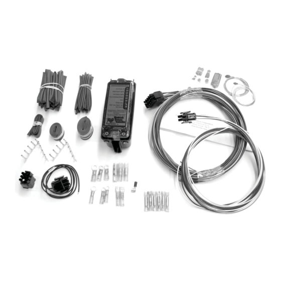
Thunder Heart Performance Corp. 615-672-8811 www.thunder-heart.com 4. Insert the wire through the blue seal into the connector body until you hear a “click.” Gently pull on the wire to ensure that the terminal is fully engaged in the housing. EHC Component Overview Throughout this manual you will be referred to the various components of the EHC system. -
Page 10: Chapter 2 System Installation
Thunder Heart Performance Corp. 615-672-8811 www.thunder-heart.com Figure 11—Handlebar Harness Connectors Figure 12—Included Terminals CHAPTER 2 SYSTEM INSTALLATION Finding a Suitable Location for the Electronic Harness Control Module Split Tank Bikes The Electronic Harness Controller (EHC) is designed to mount to the top frame tube between the gas tanks. -
Page 11: Trial Fitment Of The Harness To The Bike
Thunder Heart Performance Corp. 615-672-8811 www.thunder-heart.com Saddle Tank Bikes When using a saddle tank, an alternate mounting location must be found. The most common areas are near the oil bag and under the transmission. The mounting base may not fit in these locations. Zip ties can be used to attach the EHC to its mounting location. -
Page 12: H-D 1996-2003 Hand Control Connections
Thunder Heart Performance Corp. 615-672-8811 www.thunder-heart.com Note: The “horn” and “auxiliary power” circuits are found on both the front and rear harness connectors to allow for different mounting locations. Use the most convenient one for the horn. Both “auxiliary power” circuits may be used as needed. -
Page 13: Rear Lighting Options
Thunder Heart Performance Corp. 615-672-8811 www.thunder-heart.com circuits of the EHC. (Note: Diagnostic functions will not work for the left and right turn signals, as they will be powered from the Horn and Brake Light Switch circuits). See Appendix D, Wiring Tables and Diagrams. -
Page 14: Chapter 3 Indicators And Instrumentation
The EHC is designed to control LED-type dash indicators. LEDs are brighter, vibration resistant, more power efficient, usually don’t need to be replaced, and are generally easier to mount on a custom bike. When a Thunder Heart Performance LED indicator panel is used (such as P/N RSE4088), simply find a suitable mounting location and plug the supplied 16”... -
Page 15: Chapter 4 Operation
Thunder Heart Performance Corp. 615-672-8811 www.thunder-heart.com CHAPTER 4 OPERATION Diagnostics When the bike is first powered up, check the diagnostic LEDs on the label side of the EHC. If any of the LEDs are illuminated, the circuit whose label is next to the LED is either shorted to ground, or overloaded. -
Page 16: Appendix B Optional And Replacement Parts
Thunder Heart Performance Corp. 615-672-8811 www.thunder-heart.com Three-terminal switches such as the dimmer switch must be wired as shown for proper operation. I am not using a “kill” switch. How do I wire the right handlebar harness? You must use a “kill” switch. The kill switch is an extremely important safety device and should never be removed from the bike. -
Page 17: Appendix D Wiring Tables And Diagrams
Thunder Heart Performance Corp. 615-672-8811 www.thunder-heart.com APPENDIX D WIRING TABLES AND DIAGRAMS Table 3—Front Harness Connector Pin Assignments FUNCTION COLOR AUXILARY POWER TURN SIGNAL, LEFT FRONT PURPLE LOW BEAM YELLOW HORN YELLOWw/BLACK STRIPE TURN SIGNAL, RIGHT FRONT BROWN HIGH BEAM WHITE Table 4—Left Handlebar Connector Pin Assignments... - Page 18 Thunder Heart Performance Corp. 615-672-8811 www.thunder-heart.com Figure 17—Front Harness Wiring Diagram “Wire Side” of Connector Shown EI4250...
- Page 19 Thunder Heart Performance Corp. 615-672-8811 www.thunder-heart.com Figure 18—Pre-1996 Hand Control Wiring Diagram “Wire Side” of Connector Shown EI4250...
- Page 20 Thunder Heart Performance Corp. 615-672-8811 www.thunder-heart.com Figure 19—1996-2003 Hand Control Wiring Diagram (Partial Diagnostics) “Wire Side” of Connector Shown EI4250...
- Page 21 Thunder Heart Performance Corp. 615-672-8811 www.thunder-heart.com Figure 20—1996-2003 Hand Control Wiring Diagram (Full Diagnostics) “Wire Side” of Connector Shown EI4250...
- Page 22 Thunder Heart Performance Corp. 615-672-8811 www.thunder-heart.com Figure 21—Rear Harness Wiring Diagram Turn signals functioning as a turn signal and brake light “Wire Side” of Connector Shown EI4250...
- Page 23 Thunder Heart Performance Corp. 615-672-8811 www.thunder-heart.com Figure 22—Rear Harness Wiring Diagram (*option requires dual filament turn signal housings) Turn signals functioning as a turn signal, brake light and tail light “Wire Side” of Connector Shown EI4250...
Need help?
Do you have a question about the EA4250D and is the answer not in the manual?
Questions and answers