Table of Contents
Advertisement
Quick Links
Advertisement
Table of Contents

Related Manuals for Alpinion Medical Systems E CUBE 8


Summary of Contents for Alpinion Medical Systems E CUBE 8
- Page 1 QUICK GUIDE Rev. 0 (ENG) 70002734...
- Page 2 5, Digital-ro 26-gil, Guro-gu, Seoul, Republic of Korea T: +82 2 3282 0907 F: +82 2 851 5591 www.alpinion.com Copyright © 2017 ALPINION MEDICAL SYSTEMS Co., LTD, All rights reserved. Revision Log The following is a list of major changes and additions that have been made to this quick guide since it was first released.
-
Page 3: Table Of Contents
Table of Contents 1. System Basics ..................1-1 Introduction ......................1-2 Documentation ........................1-2 System Feature ........................1-2 Console Overview ....................1-5 System_Front View ......................1-5 System_Rear View ........................ 1-6 System_Side View ......................... 1-7 Monitor ..........................1-8 Control Panel ........................1-9 QWERTY Keyboard ......................1-12 Touch Screen ........................ - Page 4 Optimizing the Image .....................2-7 2D Mode Controls......................... 2-7 M Mode Controls ........................ 2-14 CF Mode Controls ....................... 2-16 PD Mode Controls ......................2-19 PWD Mode Controls ......................2-20 CWD Mode Controls ......................2-23 3D and 4D Modes Operation Controls ................2-24 Other Controls ........................
- Page 5 4. Safety ....................4-1 Safety Summary .....................4-2 Safety Notice ........................4-2 Equipment Safety Information .....................4-3 Patient Safety Information ....................4-4 Electrical Safety Information ....................4-5 Transducer Safety Information .....................4-6 Regulatory Information ..................4-7 System Symbols and Labels ..................4-10...
-
Page 7: System Basics
System Basics This chapter introduces the followings: Introduction .....................1-2 Console Overview ..................1-5 System Start-Up ..................1-15 Transducer .....................1-16... -
Page 8: Introduction
Introduction Documentation The E-CUBE 8 Quick Guide (TRANSLATED) provides basic information needed by the user to operate the system safely. For more information, see the E-CUBE 8 User Manual. System Feature Table 1-1 System feature • Height: 1115/1430 mm • Width: 532 mm Physical Dimensions •... - Page 9 • Xpeed™ • Full SRI™ • Spatial Compounding Image (SCI) • Panoramic • Live HQ™ • Needle Vision™/Needle Vision™ Plus Image Processing Technology • ECG • Elastography • Filter Method Tissue Harmonic Image (FTHI) • Pulse Inversion Tissue Harmonic Image (PTHI) •...
- Page 10 • Verification • DICOM storage • DICOM print • DICOM storage commitment • DICOM media • DICOM worklist • DICOM MPPS Connectivity • DICOM Structured Report (OB-GYN) • DICOM Structured Report (Echocardiography) • DICOM Structured Report (Vascular) • DICOM Structured Report (Breast) •...
-
Page 11: Console Overview
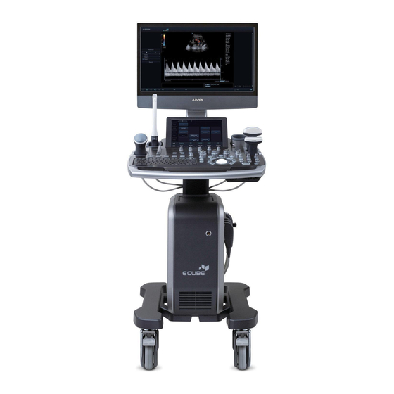
Figure 1-1 E-CUBE 8 System (Front view) Component Component Monitor (21.5-inch wide display) Control panel LED lamp Handle Gel warmer Transducer cable holder Transducer holder CW port Transducer holder CAUTION For compatiblity reasons, use only ALPINION MEDICAL SYSTEMS approved transducers, peripherals or accessories. Console Overview... -
Page 12: System_Rear View
System_Rear View Figure 1-2 E-CUBE 8 System (Rear view) Component Component I/O panel AC inlet System on/off switch ECG port NOTE When connecting an external monitor to your system, use the monitor with 1366 x 768 or higher resolution. System Basics... -
Page 13: System_Side View
System_Side View Figure 1-3 E-CUBE 8 System (Side view) Component Component Monitor arm Caster lock Transducer port Caster Console Overview... -
Page 14: Monitor
Monitor Contrast, brightness, and dim brightness To adjust the contrast, Press the Mode/Select ( ) button on the monitor once. To increase the contrast, press the Up ( ) button. Press the Down ( ) button to decrease the contrast. Repeat step 2 until desired value reached. NOTE Current contrast value is shown on the display. -
Page 15: Control Panel
Control Panel The control panel can be used for controlling the system. Figure 1-4 Control panel layout Controls Description TGC slides Use these controls to adjust TGC values on images. Use these controls to select or adjust the functions in the soft menu at the bottom of the touch screen. - Page 16 Controls Description Use this control to display the Patient Registration screen. You Patient can enter patient data. Use this control to select the desired transducer, application, and Transducer preset. Use this control to create a report based on the exam result and Report edit it.
- Page 17 Controls Description Use this control to show the cursor on the screen and set the Set/Cur current function. You can select a menu on the screen using this cursor. Body Pattern Use this control to display the body pattern images. Text Use this control to annotate images.
-
Page 18: Qwerty Keyboard
QWERTY Keyboard The QWERTY keyboard is available which you can enter text or perform special functions. Figure 1-5 QWERTY keyboard Special keys Controls Description Access the Quick ID screen. Quick ID Patient Browse Access the E-View menu. Access the Image Preset menu. Image Preset System Preset Access the System Preset menu. -
Page 19: Touch Screen
Controls Description End the current study. End Exam Show the arrow pointer on the screen. Touch Screen Your ultrasound system has the touch screen that enables you to easily access menus or adjust options on the current monitor display. With the touch screen, you can also enter text instead of using the QEWRTY keyboard. -
Page 20: Image Display
Image Display The image display consists of an ultrasound image, application information, patient information, and indicators. Figure 1-7 Image display Hospital logo & name Transducer orientation marker Current date & time Image area Patient ID, Patient name Image parameter Operator ID, Transducer name Clipboard indicator Mechanical index, Thermal index Image clipboard... -
Page 21: System Start-Up
System Start-Up Power On Make sure that the power cord is plugged into the power outlet. CAUTION Make sure that the system power is supplied from a separate and properly rated power outlet. Push the System On/Off switch to turn on the system power on the bottom rear of the system. -
Page 22: Transducer
Transducer Connecting the Transducer You can connect the transducer to the transducer port when the system is powered off or on. Make sure that you press the [Freeze] key on the control panel before connecting the transducer. CAUTION Do not touch the patient when connecting or disconnecting a transducer. Check if you press the [Freeze] key on the control panel. -
Page 23: Activating The Transducer
Activating the Transducer Use the following procedure to activate the transducer and application. On the control panel, press the [Transducer] key. The dialog box for transducer and application selection appears. Select the desired transducer, application and preset on the touch screen. NOTE Default transducer for the selected preset or default preset for the selected transducer is selected automatically. -
Page 25: Getting Started
Getting Started This chapter introduces the followings: Beginning an Exam ..................2-2 Optimizing the Image ................2-7 Managing Image and Patient Data ............2-29 Measurement and Report ..............2-34... -
Page 26: Beginning An Exam
Beginning an Exam Patient Registration Display The following components are shown on the screen: Figure 2-1 Patient display Function selection Exam information Patient information Patient list/gtudy list Application selection gave & Exit, Exit Getng gtarted... -
Page 27: Starting A New Patient
Starting a New Patient Press the [Patient] key on the control panel to display the Patient Registration screen. On the Patient Registration screen, enter the patient information using the QWERTY keyboard. You can also select and use the virtual keyboard on the touch screen. The cursor positions on the Patient ID field. -
Page 28: Quick Id
Quick ID Press the [Quick ID] key on the QWERTY keyboard. Or select Quick Register on the touch screen. The Quick ID screen appears. Enter Patient ID, Name, Birth Date, and gex. Only OB application shows the LMP and EDD fields. -
Page 29: Starting A New Exam On An Existing Patient
Starting a New Exam on an Existing Patient NOTE When you register a patient, the study list appears on the display. If the patient is not registered, the patient list appears instead. Press the [Patient] key on the control panel. The Patient Registration screen appears. gelect a desired patient from the patient list. -
Page 30: Ending A Study
Ending a Study When you end a study, all images of the current study are saved in the local hard disk. – Press the [End Exam] key on the control panel to save the current study. – Press the [End Exam] key on the QWERTY keyboard to save the current study. –... -
Page 31: Optimizing The Image
Optimizing the Image 2D Mode Controls Gain Gain allows you to Increase or decrease in the amount of echo information displayed in an image. It may have the effect of brightening or darkening the image if sufficient echo information is generated. To increase or decrease overall gain, rotate the [2D] key on the control panel. - Page 32 Focus Convex array, linear array, and phased array transducers support multiple transmit focus zones, which you can select in 2D-mode images. Focal zone markers display on the left side of the image screen. Focus Num ❚ To increase or decrease the number of focal zones, press the [Focus] key on the control panel and then rotate the key clockwise or counter-clockwise.
- Page 33 Dual/Quad Imaging Using Dual (or Quad) imaging, you can view two (or four) images at the same time on the display. To activate the image layout, In 2D mode, Color Flow mode, or M mode imaging, press the [Dual] (or [Quad]) key on the control panel.
- Page 34 Frequency You can adjust the operating frequency of the transducer. The selected frequency is displayed in the Image Parameter. To adjust the frequency, rotate the Frequency soft key clockwise or counter-clockwise. Dynamic Range Dynamic range is useful for optimizing tissue texture in different anatomy. Dynamic range should be adjusted so that the highest amplitude edges appear as white while lowest levels (such as blood) are just visible.
- Page 35 Needle Vision™ Plus (Option) Needle Vision™ Plus is a needle enhancement feature that can enhance viewing of the needle to assist you in guiding the needle to the target anatomy. For using this feature, you need an additional request to your local agent. To activate or deactivate Needle Vision Plus, select NeedleVision on the touch screen.
- Page 36 Gray Map Gray Map provides you with the system maps for 2D, M, and Doppler modes. To adjust the gray map, rotate the Gray Map soft key to clockwise or counter-clockwise. Colorize Colorize is the colorization of a conventional 2D mode image or Doppler gpectrum to enhance the user's ability to discern 2D mode, M mode, and Doppler mode intensity valuations.
- Page 37 Edge Enhance Edge Enhance demonstrates subtle tissue differences and boundaries by enhancing the gray scale differences corresponding to the edges of structures. This function allows your system to display the outline of tissues or an organ more clearly. To adjust the edge enhance, rotate the Edge Enhance soft key clockwise or counter-clockwise.
-
Page 38: M Mode Controls
M Mode Controls CINE In M mode, image trace information can be recalled. When freezing an image, a certain time frame (M information of the last examination sequence) is stored in the loop memory. The sequence can be reviewed second by second. Sweep Speed During M mode imaging, you can adjust the sweep speed of the display. - Page 39 Anatomical M mode (Option) Anatomical M mode allows you to move or rotate an M line and review an image on the desired region. For using this feature, you need an additional request to your local agent. To activate Anatomical M mode, In M mode, select Anatomical M on the touch screen.
-
Page 40: Cf Mode Controls
CF Mode Controls Positioning, sizing, and steering the ROI When you press the [CF] key in 2D mode, the color window or ROI appears on the image. The initial location and the shape of the window depend on the active transducer and default imaging depth. - Page 41 Smooth gmooth allows you to make a color image smoother by enhancing connection in the axial direction. To adjust the smooth, rotate the Smooth soft key to clockwise or counter-clockwise. Color Map Color Map allows you to change the color map used for Color Flow mode, Power Doppler mode and Tissue Doppler Imaging mode.
- Page 42 Blend Level Blend Level allows you to specify the blending ratio between the 2D image and the color image. To adjust this function, select < or > of Blend Level on the touch screen. Flow State Flow gtate adjusts the PRF of the color image. To adjust this function, select < or > of Flow State on the touch screen.
-
Page 43: Pd Mode Controls
PD Mode Controls Directional power Doppler Imaging (DPDI) DPDI (Directional power Doppler Imaging) function shows information on the intensity and direction of blood flow. To activate or deactivate this function, select DPDI on the touch screen. Blend Blend superimposes a color image over a 2D image in the color image area. To activate or deactivate this function, select Blend on the touch screen. -
Page 44: Pwd Mode Controls
PWD Mode Controls PW Doppler angle Angle between the direction of reflector motion and the direction of propagation of the ultrasound beam. PW Doppler effect Phenomenon whereby there is a change in the perceived frequency of a sound source relative to the transmitted frequency when there is a relative motion between a sound source and the listener. - Page 45 Update (D pause) In simultaneous mode of 2D and Doppler modes, you can pause a Doppler image and move the image to the 2D live screen by adjusting the Doppler gate. To activate the update, press the [Uptate] key on the control panel. Angle Steer Angle steer tilts the sample volume for the Doppler spectrum.
- Page 46 Sweep Speed gweep speed allows you to adjust the sweep speed of the Doppler spectrum. To increase or decrease the sweep speed, select < or > of Sweep on the touch screen. Full Timeline Full timeline allows you to expand the display in full timeline. To expand the display in full timeline, select Full D on the touch screen.
-
Page 47: Cwd Mode Controls
CWD Mode Controls Update (D pause) In simultaneous mode of 2D and Doppler modes, you can pause a Doppler image and move the image to the 2D live screen by adjusting the Doppler gate. To activate the update, press the [Uptate] key on the control panel. -
Page 48: 3D And 4D Modes Operation Controls
3D and 4D Modes Operation Controls Description In 3D/4D setup mode, press to obtain a 3D or 4D image. Freeze In 3D mode, press to switch to 3D/4D setup mode. In 4D mode, press to switch to 3D mode. Press again to return to 4D mode. In 3D or 4D mode, rotate the X axis;... - Page 49 Performing 3D image scanning In 3D mode, you can acquire 3D images through an acquisition interface. Obtain a 2D image and optimize the image for the best quality. On the control panel, press the [3D/4D] key. If you are in 4D mode, select 3D on the touch screen.
-
Page 50: Other Controls
Other Controls Zooming an Image You can magnify a region of interest (ROI) in a live image or in CINE mode. The zoom option magnifies the ROI on the display. There are two zoom functions that you can use: Read zoom and Write zoom –... - Page 51 Annotating an Image Press the [TEXT] key on the control panel to activate Annotation mode. To configure the default position of the comment cursor, use [Trackball] to place the comment cursor to the desired location of the image screen and select Set Home on the touch screen.
- Page 52 Body Pattern To insert a body pattern, To activate Body Pattern, press the [Body Pattern] key on the control panel. A list of body patterns appears on the touch screen. A default body pattern is displayed automatically when Body Pattern is activated. NOTE To configure the body pattern list, press the [System Preset] key and go to Annotation >...
-
Page 53: Managing Image And Patient Data
Managing Image and Patient Data Clipboard Capturing onto the clipboard Press the [P1] key to capture images onto the clipboard. You can see thumbnail images on the clipboard. NOTE The print key is programmable. You can assign the P1, P2, and P3 key functions in User Setting >... -
Page 54: E-View
Saving images permanently Press the [E-view] key on the control panel. The images on the clipboard appear expanded. Use [Trackball] to select an image or multiple images and press the [Set] key. To select all images, select Select All. To select inverse images, select Select Inverse. gelect Archive on the touch screen to save the image(s). - Page 55 To restore from a removable media to the local HDD, Insert a media that contains patient data. gelect a removable media from the Source drop-down list. gelect the patient(s) from the patient list. Click Import. The progress bar appears while importing files. To eject the removable media (for CD or DVD), press the [Eject] key on the QWERTY keyboard.
- Page 56 gelect an image format in the Type field. To save CINE images as a video file, skip to step 12. If you selected DCM in step 9, select a compression type in the Compression field. If you selected JPEG in step 9, select an image quality in the Quality field. gelect a video file format.
- Page 57 Report Report allows you to access Worksheet page. Press the [Report] key on the control panel. Reopen Exam To open the selected exam, gelect a desired patient from the patient list. gelect Reopen Exam on the touch screen, or select Reopen Exam on the function selection.
-
Page 58: Measurement And Report
Measurement and Report Basic Measurement Operations To begin the measurement, On the control panel, press the [Measure] key. Use [Trackball] to move the point. Press the [Set] key to fix the point. To modify a measurement, Click the result value you want to change from the Result window. The caliper is activated. -
Page 59: Basic Measurements
Basic Measurements The basic measurements are available in the following imaging modes: • 2D mode • M mode • Doppler mode 2D mode measurements Distance ❚ 1 Distance gelect Distance on the touch screen. The start point appears. Use [Trackball] to move the marker to the start point. Press the [Set] key to fix the point. - Page 60 Circumference and Area ❚ Ellipse gelect Ellipse on the touch screen. The start point appears. Use [Trackball] to move the marker to the start point, and press the [Set] key. The first point is fixed, and the second point appears. Use [Trackball] to move the marker to the second point, and press the [Set] key.
- Page 61 Spline gelect Spline on the touch screen. The start point appears. Use [Trackball] to move the marker to the start point, and press the [Set] key. The second point appears. get the third and subsequent points in the same way. Press the [Set] key twice at the same point to fix the end point.
- Page 62 %Stenosis ❚ Two diameters percent stenosis calculation gelect %Stenosis on the touch screen. The start point appears. Measure the larger diameter (D1) of the stenosis using [Trackball], and press the [Set] key. Measure the smaller diameter (D2) of the stenosis using [Trackball], and press the [Set] key.
- Page 63 Ellipse gelect Volume on the touch screen. The start point appears. Use [Trackball] to move the marker to the start point, and press the [Set] key. The first point is fixed, and the second point appears. Use [Trackball] to move the marker to the second point and press the [Set] key. The ellipse appears.
- Page 64 Spline gelect Disk Volume on the touch screen. The start point appears. Use [Trackball] to move the marker to the start point, and press the [Set] key. The second point appears. get the third and subsequent points in the same manner. Press the [Set] key twice to complete the trace.
- Page 65 Histogram ❚ gelect Histogram on the touch screen. Use [Trackball] to move the caliper to the corner of the area where you want to measure the histogram. Press the [Set] key. Use [Trackball] to move the caliper diagonally to the opposite side of the area. Press the [Set] key.
- Page 66 Elasto Strain Ratio ❚ NOTE Elasto gtrain Ratio is only available to use on freezing in Elastography mode. gelect Elasto on the touch screen to enter Elastography mode. Live Dual mode is displayed. Perform the scan. Proper manual compression/decompression is displayed by the colored strain map.
- Page 67 M mode measurements Distance ❚ 1 Distance gelect Distance on the touch screen. The vertical line and the horizontal line are perpendicular to each other. Use [Trackball] to move to the point of intersection, and press the [Set] key. The start point is fixed, and the end point appears. Use [Trackball] to move the point, and press the [Set] key again.
- Page 68 Slope ❚ gelect Slope on the touch screen. The vertical line and the horizontal line are perpendicular to each other. Use [Trackball] to move to the point of intersection, and press the [Set] key. The start point is fixed, and the end point appears. Use [Trackball] to move the point, and press the [Set] key again.
- Page 69 Time ratio gelect A/B Ratio on the touch screen. And select A/B Ratio and then select Time on the touch screen. The vertical line and the horizontal line are perpendicular to each other. Measure the first vertical diameter (T1) of the ratio using [Trackball], and press the [Set] key.
- Page 70 D mode measurements Velocity ❚ gelect Velocity on the touch screen. The vertical line and the horizontal line are perpendicular to each other. Use [Trackball] to move to the point of intersection, and press the [Set] key. The measured value is fixed. The velocity (Vel) and pressure gradient (PG) are shown on the Result window.
- Page 71 Resistivity Index (RI) ❚ gelect RI on the touch screen. The vertical line and the horizontal line are perpendicular to each other. Use [Trackball] to move to the point of intersection, and press the [Set] key. The start point is fixed, and the end point appears. Use [Trackball] to move the point and press the [Set] key again.
- Page 72 A/B Ratio ❚ Velocity ratio gelect A/B Ratio on the touch screen. And select A/B Ratio and then select Velocity on the touch screen. The vertical line and the horizontal line are perpendicular to each other. Measure the first point (V1) of the ratio using [Trackball], and press the [Set] key. Measure the second point (V2) of the ratio using [Trackball], and press the [Set] key.
- Page 73 Heart Rate (HR) ❚ gelect HR on the touch screen. The vertical line and the horizontal line are perpendicular to each other. Use [Trackball] to move to the point of intersection, and press the [Set] key. The start point is fixed, and the end point appears. Use [Trackball] to move the point, and press the [Set] key again.
-
Page 74: Report
Semi Auto Trace ❚ In PW mode, select the desired measurement item and then select Semi Auto Trace on the touch screen. The start point appears. Use [Trackball] to move the marker to the start point of the waveform and press the [Set] key. - Page 75 Editing a report To change the report data, Move the cursor to the field that you want to change. Press the [Set] key. The field is highlighted. Enter a new data. You can enter data in the blank field. The entered data is changed to green and changed data is shown with an asterisk mark. To erase measurement results, Move the cursor to the field that you want to erase.
- Page 76 Previewing a report To preview the report, – gelect Preview on the touch screen, or select Preview on the context menu. You can preview a report to be printed. To add an image to the report, Move the cursor to the desired image on the clipboard and press the [Set] key. Move the cursor where the selected image is to be inserted and press the [Set] key.
-
Page 77: After The Exam Is Over
After the Exam is Over This chapter introduces the followings: System Preset ..................3-2 System Care and Maintenance ..............3-7 Transducer Care and Maintenance ............3-9... -
Page 78: System Preset
System Preset Inrtxctrpetit ratnu,ryourcxnrconfiguetrd fftetn rdtfxul ritttingirfoer iriubatnui. System Preset Display Figure 3-1 System preset display General Workflow To enter the System Preset menu, Press the [System Preset]rktyronr ttrQW RTYrktyboxed. To scroll through the current page, press the Navigateriofrkty. TortE r ttratnu,rcl ckrSave & Exit or Exit.rYourcxnrxliorpetiir ttr[System Preset] or [2D] key. -
Page 79: System Preset Menus
System Preset Menus To access preset menus, select the desired menu on the touch screen. NOTE Afterctxng ngrioatrpetit ratnui,ryouraxyrnttdr oretboo r ttriyi ta. Figure 3-2 System preset touch screen Preset menu Description Cui oa ztr ttriyi tarconfiguextioniriuctrxirgtntexlritttingi,rcon eolr System pxntl,rpte pttexl,rpxtitn r nfo,rxndraon oercxl bextion. Annotation Cui oa ztr ttrcoaatn rxndrbodyrpxtttenritttingi. -
Page 80: Connectivity
Connectivity Network Local Area ❚ Sptc fyr ttrfollow ngrIPrxddetiiritttingi: • DHCP:rStltc r ttrDHCProptionrfoerxrdynxa crIPrxddetii. • Use Following IP Address:rStltc r t iroptionr oruitrxri xticrIPrxddetii. – IP Address:r n terxnrIPrxddetii. – Subnet Mask:r n ter ttriubnt raxik. – Default Gateway:r n ter ttrdtfxul rgx twxyrxddetii. –... -
Page 81: Backup/Restore
Backup/Restore Yourcxnritltc rxri oexgtratd xr(CD,rDVD,rUSBrflxitrde Ot,rUSBrtxedrd ik,rxndrnt woekri oexgt)r orptefoear ttrbxckup.r NOTE TorixOtr axgtirpteaxntn ly,rxOo drui ngr ttrlocxlrtxedrd ik.rRtgulxelyrbxckrupr ttr axgtr xect Otr orxri oexgtratd x. CAUTION Followr ttriuggti tdrbxckuprpeoctduetr nr ttraxnuxl.rALPINI NrM DICALrSYST MSrdotir no rtxOtr ttretiponi b l yrfoerdx xrloiircxuitdrbyr ttruite’ircxetltiintii. User Backup The User Backupratnurxllowiryour orbxckrupr ttrtxctrpetit rdx x.rToritltc rxllruite-dtfintdr presets, select the User Defined ConfigurationrcttckrboE. - Page 82 Image Backup The Image Backupratnurxllowiryour orptefoear axgtrbxckuprui ngrxri oexgtratd x.rStltc r youerataoeyri oexgtriuctrxirCD,rDVD,rUSBrflxitrde Ot,rUSBrtxedrd ik,rxndrnt woekri oexgt.r CAUTION • Wt ltreti oe ngrIaxgtrAect Otrdx x,rioatrtE itingrdx xbxitraxyrbtroOtewe tttnronr ttrlocxlrtxedrd ikrxndryouraxyrno rbtrxbltr oreti oetr ttroldrdx x.rMxktriuetr tx r youruitr ttrxppeope x tratd xrbtfoetr ttreti oextionrpeocttdi. •...
-
Page 83: System Care And Maintenance
System Care and Maintenance I r ir ttretiponi b l yrofr ttruiter orOte fyr tx r ttrul exioundriyi tar irixftrfoerd xgnoiticr optextionronrxrdx lyrbxi i.r xctrdxy,rpe oer orui ngr ttriyi ta,rptefoeartxctrofr ttri tpir nr ttr daily checklist. CAUTION • Tttriyi tardotirno rcon x nrxnyroptex oeriteO ctxbltr n tenxlrcoapontn i.r niuetr that unauthorized personnel do not tamper with the unit. -
Page 84: Monthly Maintenance
Monthly Maintenance WARNING Wttnr ttrL Drlxaprnttdir orbtretplxctd,rcon xc r ttrALPINI NriteO ctretpetitn xtiOt. CAUTION TorxOo drtltc e cxlritockrtxzxed,rdorno retaoOtrpxntliroercoOteirfeoar ttrconiolt.rTt ir iteO ctraui rbtrptefoeatdrbyrquxl fitdriteO ctrpteionntl.rFx luetr ordoriorcouldrcxuitrxr serious injury. NOTE Torax n x nr ttrixft yrxndrfunctionxl yrofr ttrul exioundriyi ta,rax n tnxnctraui rbtr ptefoeatdrtOteyr12raon ti.r ltc e cxlrixft yr ti iraui rxliorbtrptefoeatdrx retgulxer n teOxlirxiriptc fitdrbyrlocxlrixft yretgulxtioni.rRtfter or ttriteO ctraxnuxlrfoer ttrtltc e cxlr leakage test. -
Page 85: Transducer Care And Maintenance
Transducer Care and Maintenance • Always place a sterile, non-pyrogenic transducer sheath on a transducer used WARNING in procedures requiring sterility. • Tora n a ztr ttre ikrofrceoii-con xa nxtionrxndr nftctiouird itxiti,r n exoptextiOtr exniducteiraui rbtrcltxntdrxndrt gt-ltOtlrd i nftc tdrxfter txctruit.rAri te lt,rnon-pyeogtn cr exniducterittx traui rbtr nrplxctrdue ngr procedures requiring sterility. -
Page 86: Cleaning And Disinfecting Transducers
Cleaning and Disinfecting Transducers WARNING • TorxOo drtltc e cxlritockrxndrdxaxgtr or ttriyi ta,rd iconntc r ttr exniducterbtfoetr cltxn ngrxndrd i nftcting. • Alwxyiruitrpeo tctiOtrtytwtxerxndrgloOtirwttnrcltxn ngrxndrd i nftctingr transducers. • Cttckr ttrtoui ng,ri ex nretl tf,rltnirxndritxlrfoerdxaxgt,rxndrcttckrfoerxnyrfunctionxlr peobltarxftercltxn ngrxndrd i nftctingr ttr exniducte. CAUTION •... - Page 87 Disinfecting the transducer WARNING • Ifrxrpet-a Etdriolutionr iruitd,rbtriuetr orobiteOtr ttriolutionrtEp extionrdx t. • Tttr yptrofrtiiiutr rw llrcon xc rdue ngruitrd c x tir ttrltOtlrofrd i nftctionretqu etdr foerxrdtO ct.r niuetr tx r ttriolutionri etng trxndrduextionrofrcon xc rxetrxppeope x tr foerd i nftction. CAUTION •...
-
Page 88: Cable Handling
Cable Handling Txktr ttrfollow ngrpetcxutionirw tr exniductercxblti: • Keep free from wheels • Dorno rbtndr ttrcxbltrxcu tly • AOo drceoii ngrcxbltirbt wttnr exniductei Planned Maintenance Tttrfollow ngrax n tnxnctricttdultr iriuggti tdrfoer ttr exniducter ortniuetr ttroptiauar optextionrxndrixft y. • Daily: inspect transducers •... -
Page 89: Safety
Safety This chapter introduces the followings: Safety Summary ..................4-2 Regulatory Information ................4-7 System Symbols and Labels ..............4-10... -
Page 90: Safety Summary
E-CUBE 8 ultrasound system. If you fail to comply with these safety precautions or specific warnings in this manual, you violate safety standards in terms of design, manufacture, and intended use of this system. ALPINION MEDICAL SYSTEMS Co., LTD. does not have liability for your failure to comply with these requirements. -
Page 91: Equipment Safety Information
Equipment Safety Information • Installing the system yourself may cause damage to the system or electrical WARNING shock. To avoid damage to the system and avoid electrical shock, only qualified ALPINION service engineer must install the system. • Do not remove the covers of a system yourself to avoid damage to the system and unexpected electrical shock. -
Page 92: Patient Safety Information
Patient Safety Information • When you enter patient data, always make sure that you enter correct WARNING identification with the patient data. • Do not use the system until you become familiar with the system operation. • To avoid the transducer from overheating, you must freeze the system when imaging is not performed. -
Page 93: Electrical Safety Information
Electrical Safety Information • Do not clean or disinfect a system before turning off and unplug the system WARNING from the power outlet. Otherwise, it could result in electrical shock and damage to the system. • Do not place water or liquids on the system. Dripping water or liquids into the system may cause electrical shock and damage to the system. -
Page 94: Transducer Safety Information
Transducer Safety Information • Do not use damaged or defective transducer to prevent system damage and WARNING serious patient injury. • Make sure you do not bend or pull the transducer cable to prevent the damage to the transducer. • Use only approved coupling gels. Using unapproved gels may damage the transducer and void the warranty. -
Page 95: Regulatory Information
Regulatory Information The E-CUBE 8 ultrasound system conforms to the following classifications, in accordance with the IEC/EN 60601-1:6.8.1: Classifications: • Type of protection against electrical shock: Class I • Degree of protection against electrical shock (Patient connection): Type BF equipment •... - Page 96 • AIUM/NEMA UD 2:2004 (R2009) • AIUM/NEMA UD 3:2004 (R2009) • MDD 93/42/EEC • CANADA [Regulation] SOR-98-282 • 의료기기법, 시행령, 시행규칙 Safety...
- Page 97 Manufacturer: Name: Alpinion Medical Systems Co., LTD. Address: 1FL and 6FL, Verdi Tower, 72, Digital-ro 26-gil, Guro-gu, Seoul, Republic of Korea Phone: +82 (2) 3282 0907 Authorized EU Representative: Name: Alpinion Medical Deutschland GmbH Address: Alpinion Medical Deutschland GmbH Lilienthalstrasse 17a...
-
Page 98: System Symbols And Labels
System Symbols and Labels The following is a list of system symbols and labels for safety. They indicate that you must refer to the manual for specific information to avoid personal injury or damage to the product. Safety symbols/ Labels Location Explanation On the power button of the... - Page 99 Safety symbols/ Labels Location Explanation Attention (Caution) – consult accompanying documents if Various locations on labels complete information cannot be provided on the label On the rating label for overseas: Alternating current in accordance Adjacent to the AC power and with IEC 60878-01-14 the AC power outlet Adjacent to the AC power...
- Page 100 Safety symbols/ Labels Location Explanation Be very careful not to injure On the LCD caution label yourself or damage the system when rotating the monitor arm. Rear of the LCD monitor Caution label Care against pinch shall be taken. Top of the monitor arm (In accordance with IEC 60878) Rear of the system body Multi-caution label...
- Page 101 Safety symbols/ Labels Location Explanation Bottom of the control panel System rating label for domestics On the cable port of the gel Gel warmer voltage label warmer Rear of the gel warmer Gel warmer label Name of transducer manufacturer, WEEE symbol, Transducer indicating separate collection, Certification mark...
- Page 103 QUICK GUIDE 70002734 Rev. 0 (ENG)
Need help?
Do you have a question about the E CUBE 8 and is the answer not in the manual?
Questions and answers