Table of Contents
Advertisement
INSTALLATION GUIDE
BNC-2120
Connector Accessory for E/M/S Series Devices
This installation guide describes how to install, configure, and use your BNC-2120 accessory with
68-pin or 100-pin E/M/S Series multifunction data acquisition (DAQ) devices. This document also
contains accessory specifications.
The BNC-2120 has the following features:
•
Eight BNC connectors for analog input (AI) connection
•
Onboard temperature reference
•
Thermocouple connector
•
Resistor measurement screw terminals
•
Two BNC connectors for analog output (AO) connection
•
Screw terminals for digital I/O (DIO) connection with state indicators
•
Screw terminals for timing I/O (TIO) connection
•
Two user-defined BNC connectors
•
A function generator with the following outputs:
-
Frequency-adjustable, TTL-compatible square wave
-
Frequency- and amplitude-adjustable sine wave or triangle wave
•
Quadrature encoder
•
A 68-pin I/O connector that connects to multifunction DAQ devices
•
Can be used on a desktop or mounted on a DIN rail
Contents
Conventions ......................................................................................................................................... 2
What You Need to Get Started ............................................................................................................ 2
Installing the BNC-2120 ...................................................................................................................... 2
Connecting Analog Input Signals ........................................................................................................ 5
Connecting Differential Analog Input Signals ............................................................................ 5
Measuring Floating Signals ................................................................................................. 5
Measuring Ground-Referenced Signals............................................................................... 6
Measuring Temperature............................................................................................................... 6
Measuring Resistance .................................................................................................................. 7
Connecting Analog Output Signals ..................................................................................................... 7
Using the Function Generator.............................................................................................................. 8
Connecting Timing I/O Signals ........................................................................................................... 8
Using the Quadrature Encoder..................................................................................................... 10
Connecting User-Defined Signals ....................................................................................................... 10
Connecting Digital I/O Signals............................................................................................................ 11
Specifications....................................................................................................................................... 11
Advertisement
Table of Contents

Related Manuals for National Instruments BNC-2120


Summary of Contents for National Instruments BNC-2120
-
Page 1: Table Of Contents
INSTALLATION GUIDE BNC-2120 Connector Accessory for E/M/S Series Devices This installation guide describes how to install, configure, and use your BNC-2120 accessory with 68-pin or 100-pin E/M/S Series multifunction data acquisition (DAQ) devices. This document also contains accessory specifications. The BNC-2120 has the following features: •... -
Page 2: Conventions
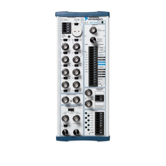
Installing the BNC-2120 Figure 1 shows the front panel of the BNC-2120. You can use two BNC-2120 accessories with both connectors of NI 6224/6229/6254/6259/6284/6289 M Series devices. You cannot use the BNC-2120 with Connector 1 of NI 6225/6255 devices. BNC-2120 Installation Guide... - Page 3 15 Amplitude Adjust Knob 23 Timing I/O BNC Connector Analog Input BNC Connectors 16 Digital I/O Screw Terminals 24 Power Indicator LED FS/GS Switches 17 Digital I/O LEDs Figure 1. BNC-2120 Front Panel © National Instruments Corporation BNC-2120 Installation Guide...
- Page 4 To connect the BNC-2120 to your DAQ device, complete the following steps. Consult your computer or PXI/PXI Express chassis user manual for specific instructions and warnings. Note If you have not already installed your DAQ device, refer to the DAQ Getting Started Guide for instructions.
-
Page 5: Connecting Analog Input Signals
Connecting Differential Analog Input Signals Use the BNC-2120 BNC connectors on the front panel to connect AI <0..7> signals to your DAQ device. The BNC-2120 is only intended for differential analog input signals. The number of connectors you use depends on your DAQ device and application. -
Page 6: Measuring Ground-Referenced Signals
Figure 3. Measuring a Ground-Referenced Signal Source AI GND and AI SENSE signals are located at the analog input screw terminals of the BNC-2120. When connecting signals to the screw terminals, use 28–16 AWG wire with the insulation stripped to 0.28 in. -
Page 7: Measuring Resistance
Refer to your DAQ device documentation for information about the use of these signals. When using the BNC-2120 with Connector 1 of NI 6229/6259/6289 devices, the AO <0..1> BNCs on the BNC-2120 map to the AO <2..3> channels on the M Series device. -
Page 8: Using The Function Generator
Connect the timing I/O signals of your DAQ device to the PFI 0/P1.0 (AI START TRIG) BNC or the timing I/O screw terminals on the BNC-2120. When connecting signals to the screw terminals, use 28–16 AWG wire with the insulation stripped to 0.28 in. - Page 9 Table 2. BNC-2120 Timing I/O BNC/Terminal Descriptions (Continued) BNC/Terminal Description PFI 4/P1.4 Programmable Function Input channel 4 or Port 1 Digital Input/Output channel 4 CTR 1 GATE (Counter 1 Gate Signal)—As an output, this pin is the Ctr1Gate signal. This signal reflects the actual gate signal connected to the general-purpose counter 1.
-
Page 10: Using The Quadrature Encoder
The USER 1 and USER 2 BNC connectors allow you to use a BNC connector for a digital I/O or timing I/O signal of your choice. The USER 1 and USER 2 BNC connectors are routed (internal to the BNC-2120) to the USER 1 and USER 2 screw terminals, as shown in Figure 5. USER 1 BNC... -
Page 11: Connecting Digital I/O Signals
Connect to the digital I/O signals of your DAQ device to the digital I/O screw terminals, P0.<0..7>, on the BNC-2120. You can individually configure each signal as an input or output. D GND is available at the screw terminals to supply the reference for the DIO signals. When connecting signals to the screw terminals, use 28–16 AWG wire with the insulation stripped to 0.28 in. - Page 12 Powered on.............+10/–5 V Drive ..............0.6 V, 8 mA 1.6 V, 24 mA ..............4.4 V, 8 mA 4 V, 13 mA Function Generator Square wave ............TTL-compatible Frequency range..........100 Hz to 1 MHz Frequency adjust ..........Through the Frequency Adjust knob BNC-2120 Installation Guide ni.com...
- Page 13 BNC connector ............1, for PFI 0/AI START TRIG Protection (DC max V) Powered off ............±1.7 V Powered on.............+6.7/–1.7 V Quadrature Encoder Screw terminals............2 Output signals PULSES ............96 pulses/revolution UP/DN ............High for clockwise rotation, low for counterclockwise rotation Pulse width.............1 μs © National Instruments Corporation BNC-2120 Installation Guide...
- Page 14 • EN 61326 EMC requirements; Minimum Immunity • EN 55011 Emissions; Group 1, Class A • CE, C-Tick, ICES, and FCC Part 15 Emissions; Class A Note For EMC compliance, operate this device with shielded cables. BNC-2120 Installation Guide ni.com...
- Page 15 Certification column. Environmental Management National Instruments is committed to designing and manufacturing products in an environmentally responsible manner. NI recognizes that eliminating certain hazardous substances from our products is beneficial not only to the environment but also to NI customers.
- Page 16 Instruments trademarks. Other product and company names mentioned herein are trademarks or trade names of their respective companies. For patents covering National Instruments products, refer to the appropriate location: Help»Patents in your software, the patents.txt file on your CD, or ni.com/patents.
Need help?
Do you have a question about the BNC-2120 and is the answer not in the manual?
Questions and answers