Table of Contents
Advertisement
USER GUIDE
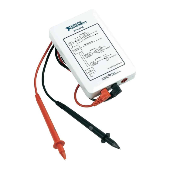
NI myDAQ
NI myDAQ is a low-cost portable data acquisition (DAQ) device that uses NI LabVIEW-based
software instruments, allowing students to measure and analyze real-world signals. NI myDAQ
is ideal for exploring electronics and taking sensor measurements. Combined with NI LabVIEW
on the PC, students can analyze and process acquired signals and control simple processes
anytime, anywhere.
Contents
Safety Information .................................................................................................................... 2
Electromagnetic Compatibility Guidelines .............................................................................. 3
NI myDAQ Hardware Overview.............................................................................................. 3
Analog Input (AI) ............................................................................................................. 4
Analog Output (AO) ......................................................................................................... 4
Digital Input/Output (DIO)............................................................................................... 5
Power Supplies ................................................................................................................. 5
Digital Multimeter (DMM) .............................................................................................. 5
NI myDAQ Software Overview ............................................................................................... 6
NI ELVISmx Driver Software.......................................................................................... 6
NI LabVIEW and NI ELVISmx Express VIs .................................................................. 6
NI myDAQ and NI Multisim............................................................................................ 6
Getting Started.......................................................................................................................... 6
Français
Deutsch
ni.com/manuals
Figure 1. NI myDAQ
Advertisement
Table of Contents

Related Manuals for National Instruments myDAQ


Summary of Contents for National Instruments myDAQ
-
Page 1: Table Of Contents
Deutsch ni.com/manuals NI myDAQ is a low-cost portable data acquisition (DAQ) device that uses NI LabVIEW-based software instruments, allowing students to measure and analyze real-world signals. NI myDAQ is ideal for exploring electronics and taking sensor measurements. Combined with NI LabVIEW on the PC, students can analyze and process acquired signals and control simple processes anytime, anywhere. -
Page 2: Safety Information
Example: Measuring Signals Using the NI ELVISmx Oscilloscope Express VI with NI myDAQ ......................28 Using NI-DAQmx with NI myDAQ ................30 Example: Measuring Audio Pass-Through in LabVIEW with NI myDAQ ..... 30 Texas Instruments Components in NI myDAQ................ 34 Resource Conflicts ........................35 Additional Resources ........................ -
Page 3: Electromagnetic Compatibility Guidelines
NI myDAQ. Figure 2 depicts the arrangement and function of the NI myDAQ subsystems. Refer to Table 5 for more information on all of the Texas Instruments components used in NI myDAQ. NI myDAQ User Guide | © National Instruments | 3... -
Page 4: Analog Input (Ai)
Note: NI myDAQ components may be changed or substituted without notice. Analog Input (AI) There are two analog input channels on NI myDAQ. These channels can be configured either as general-purpose high-impedance differential voltage input or audio input. The analog inputs are multiplexed, meaning a single analog-to-digital converter (ADC) is used to sample both channels. -
Page 5: Digital Input/Output (Dio)
5 V CMOS logic levels. Power Supplies There are three power supplies available for use on NI myDAQ. +15 V and -15 V can be used to power analog components such as operational amplifiers and linear regulators. +5 V can be used to power digital components such as logic devices. -
Page 6: Ni Mydaq Software Overview
NI ELVISmx in NI Multisim. Getting Started Getting started with NI myDAQ is a simple process, but it is important to ensure that you install the right components in the correct order. To get started with your NI myDAQ, complete the following steps: Install the NI myDAQ Software Suite from the DVD shipped with your device. -
Page 7: Making Signal Connections With Ni Mydaq
Insert and remove the 20-position screw terminal connector aligned Caution evenly to the NI myDAQ. Inserting the screw terminal connector at an angle to the NI myDAQ may cause damage to the connector. The screw terminal connector must snap securely into place to ensure proper signal connection. - Page 8 Figure 3. NI myDAQ Connection Diagram NI myDAQ 20-Position Screw Terminal Connector USB Cable Audio Cable DMM Banana Cable 8 | ni.com | NI myDAQ User Guide...
-
Page 9: Connecting Signals
Input or Digital I/O Signals—General-purpose Output digital lines or counter signals DGND — — Digital Ground—Reference for the DIO lines and the +5 V supply DGND Output 5 V power supply NI myDAQ User Guide | © National Instruments | 9... -
Page 10: Connecting Analog Input Signals
A ground-referenced signal source is connected to the building system ground, so it is already connected to a common ground point with respect to the NI myDAQ device, assuming that the computer is plugged into the same power system. Instruments or devices with nonisolated outputs that plug into the building power system are ground-referenced signal sources. - Page 11 An instrument or device that has an isolated output is a floating signal source. You must connect the ground reference of a floating signal to an NI myDAQ AGND pin through a bias resistor or jumper wire to establish a local or onboard reference for the signal.
- Page 12 AGND. If the source has high output impedance, balance the signal path as previously described using the same value resistor on both the positive and negative inputs. 12 | ni.com | NI myDAQ User Guide...
-
Page 13: Ni Mydaq Dmm Fuse Replacement
NI myDAQ DMM Fuse Replacement NI myDAQ has a fuse to protect the device from overcurrent through HI (A) current measurement input on the DMM. If the NI ELVISmx DMM software instrument always reads 0 A current, the cause may be a blown fuse. - Page 14 Replace the broken fuse while referring to Figure 10 for the fuse location, taking care to not damage any components on the board. Figure 10. NI myDAQ Fuse Location Enclosure Screws Internal Fuse—1.25 A Fast-Acting (Littelfuse Part Number 02161.25) Replace the lid and screws. 14 | ni.com | NI myDAQ User Guide...
-
Page 15: Digital I/O (Dio) And Counters/Timers
Digital I/O (DIO) and Counters/Timers There are eight, software-timed DIO lines on the NI myDAQ that can be individually configured for input or output. Additionally, lines DIO <0..4> can be configured for counter/timer functionality. The input—accessed through DIO 0, DIO 1, and DIO 2 signals configured as a counter—is used for counter, timer, pulse width measuring, and quadrature encoding... -
Page 16: Using Ni Mydaq With Ni Elvismx Software Instruments
Before opening an NI ELVISmx software instrument, make sure that the Note myDAQ device is connected to the system and is ready to use. After the myDAQ is connected to the system, the blue LED by the connector lights, indicating the device is ready for use. -
Page 17: Ni Elvismx Instrument Launcher
To launch an instrument, click the button corresponding to the desired instrument. Select the NI myDAQ device from the Device control pull-down dialog. Some instruments perform similar operations using the same resources of the NI myDAQ hardware and therefore cannot run at the same time. If you launch two instruments with overlapping functionality that cannot run at the same time, the NI ELVISmx software generates an error dialog describing the conflict. -
Page 18: Digital Multimeter (Dmm)
Digital Multimeter (DMM) The NI ELVISmx Digital Multimeter (DMM) is a stand-alone instrument that controls the basic DMM capabilities of NI myDAQ. This commonly used instrument can perform the following types of functions: • Voltage measurement (DC and AC) •... -
Page 19: Oscilloscope (Scope)
• Trigger settings: Immediate and Edge Trigger Types are supported. When using Edge Trigger Type, you can specify a Horizontal Position of 0% to 100%. Figure 13. NI ELVISmx Oscilloscope NI myDAQ User Guide | © National Instruments | 19... -
Page 20: Function Generator (Fgen)
The FGEN uses AO 0 or AO 1 on the screw terminal connector. This instrument has the following measurement parameters: • Output channel: AO 0 or AO 1 • Frequency range: 0.2 Hz to 20 kHz Figure 14. NI ELVISmx Function Generator 20 | ni.com | NI myDAQ User Guide... -
Page 21: Bode Analyzer
Bode analysis by inverting the Op-Amp signal polarity. Refer to the NI ELVISmx Help for required hardware connections. To access this help file, go to Start»All Programs»National Instruments»NI ELVISmx for NI ELVIS & NI myDAQ»NI ELVISmx Help. -
Page 22: Dynamic Signal Analyzer (Dsa)
Source Channel: AI 0 and AI 1; AudioInput Left and AudioInput Right • Voltage Range: – For AI channels: ±10 V, ±2 V – For AudioInput channels: ±2 V Figure 16. NI ELVISmx Dynamic Signal Analyzer 22 | ni.com | NI myDAQ User Guide... -
Page 23: Arbitrary Waveform Generator (Arb)
NI Waveform Editor into the NI ELVISmx ARB to generate stored waveforms. Refer to the NI ELVISmx Help for more information about the Waveform Editor. To access this help file, go to Start»All Programs»National Instruments»NI ELVISmx for NI ELVIS & NI myDAQ» NI ELVISmx Help. -
Page 24: Digital Reader
Digital Reader The NI ELVISmx Digital Reader reads digital data from the NI myDAQ digital lines. NI ELVISmx Digital Reader groups the I/O lines into ports through which data can be read. You can read one port at a time, either continuously or as a single reading. The lines are grouped into two ports of four pins (0 to 3 and 4 to 7) or one port of eight pins (0 to 7). -
Page 25: Digital Writer
The output of the NI ELVISmx Digital Writer stays latched until either another pattern is generated, the lines it is using are configured for read, or the power is cycled on the NI myDAQ. Figure 19. NI ELVISmx Digital Writer... -
Page 26: Example: Measuring A Signal Using The Ni Elvismx Oscilloscope With Ni Mydaq
LED by the connector lights, indicating the device is ready for use. Connect the signal(s) you want to measure to the connector(s) on the side of the NI myDAQ device. Launch the NI ELVISmx Scope from the NI ELVISmx Instrument Launcher. -
Page 27: Using Ni Mydaq With Labview
This section provides an overview of using NI myDAQ with LabVIEW. NI ELVISmx Express VIs in LabVIEW With NI ELVISmx, the NI myDAQ instruments have an associated LabVIEW Express VI. Express VIs allow you to interactively configure the settings for each instrument. This enables you to develop LabVIEW applications without extensive programming expertise. -
Page 28: Example: Measuring Signals Using The Ni Elvismx Oscilloscope Express Vi With Ni Mydaq
Select the NI ELVISmx Oscilloscope Express VI from the VI palette and place it on the block diagram. The NI ELVISmx Oscilloscope configuration window opens. Connect the signal(s) you want to measure to the connector(s) on the side of the NI myDAQ device. - Page 29 Oscilloscope Express VI to enable Channel 1. 10. Click the Run button to begin acquiring the measurement. You should see the signal(s) in the graphs on the VI front panel. Run Button NI myDAQ User Guide | © National Instruments | 29...
-
Page 30: Using Ni-Daqmx With Ni Mydaq
Using NI-DAQmx with NI myDAQ NI myDAQ is supported by NI-DAQmx, and therefore you can program it using the DAQ Assistant Express VI. Figure 20 shows the DAQ Assistant Express VI. Figure 20. DAQ Assistant Express VI In NI-DAQmx, DIO <0..7> appear as P0.<0..7>. - Page 31 Voltage to select a Voltage task. 13. In the Supported Physical Channels window, select audioOutputLeft from under the Devx (NI myDAQ) option. You can also press <Ctrl> while clicking audioOutputRight to select both channels. 14. Click Finish to exit the Create New Express Task dialog.
- Page 32 19. Add a While Loop to the block diagram by right-clicking the block diagram window and selecting Programming»Structures»While Loop from the Functions palette, and drag out a rectangular region to enclose both DAQ Assistant Express VIs. 32 | ni.com | NI myDAQ User Guide...
- Page 33 This example provides the basis for audio measurement. Experiment further by placing digital signal processing steps such as filters between the input and output. NI myDAQ User Guide | © National Instruments | 33...
-
Page 34: Texas Instruments Components In Ni Mydaq
Integrated circuits supplied by Texas Instruments form the power and analog I/O subsystems of NI myDAQ. Figure 2 depicts the arrangement and function of the NI myDAQ subsystems. Table 5 lists all of the Texas Instruments components used in NI myDAQ. Visit www.ti.com... -
Page 35: Resource Conflicts
Resource Conflicts Table 6 summarizes the resource conflicts you might encounter if you run certain NI myDAQ circuitry simultaneously. To use the information in Table 6, find the instrument you want to use in the left column. That row lists all the functions that are resource conflicts. - Page 36 36 | ni.com | NI myDAQ User Guide...
-
Page 37: Additional Resources
NI ELVISmx Help—This help file contains information about the NI ELVISmx software, including information on using NI ELVISmx software instruments and NI ELVISmx Express VIs. To access this help file, go to Start»All Programs»National Instruments»NI ELVISmx for NI ELVIS & NI myDAQ»NI ELVISmx Help. -
Page 38: Other Resources
Virtual Instrument A software program and hardware device that work together to create a user-defined measurement system. 38 | ni.com | NI myDAQ User Guide... -
Page 39: Warranty
NI product. Refer to the Export Compliance Information at ni.com/legal/export-compliance for the National Instruments global trade compliance policy and how to obtain relevant HTS codes, ECCNs, and other import/export data. NI MAKES NO EXPRESS OR IMPLIED WARRANTIES AS TO THE ACCURACY OF THE INFORMATION CONTAINED HEREIN AND SHALL NOT BE LIABLE FOR ANY ERRORS.
Need help?
Do you have a question about the myDAQ and is the answer not in the manual?
Questions and answers