Table of Contents
Advertisement
Advertisement
Table of Contents

Related Manuals for insys icom Powerline GP


Summary of Contents for insys icom Powerline GP
- Page 1 INSYS Powerline GP...
- Page 3 Copyright © November 2017 INSYS MICROELECTRONICS GmbH Any duplication of this manual is prohibited. All rights on this documentation and the devices are with INSYS MICROELECTRONICS GmbH Regensburg. Trademarks The use of a trademark not shown below is not an indication that it is freely availa- ble for use.
-
Page 4: Table Of Contents
Content Preface ..................... 6 Defects Liability Terms ..................6 Feedback ....................... 6 Marking of Warnings and Notes ................7 Symbols and the Formatting in this Manual ............8 Safety ....................... 9 Intended Use ......................9 Permissible Technical Limits .................. 9 Responsibilities of the Operator ................ - Page 5 Contents Maintenance, Repair and Troubleshooting ..........52 10.1 Maintenance ......................52 10.2 Troubleshooting ....................52 10.3 Repair ........................52 Waste Disposal ..................53 11.1 Repurchasing of Legacy Systems ................ 53 Declaration of Conformity ..............54 Licenses ....................55 Tables and Diagrams................72 14.1 List of Tables .......................
-
Page 6: Preface
We are looking forward to any of your feed- back. Please send an e-mail to support@insys-tec.de. We'd like to know your applications. Please send us a few headwords that we know the applications you solve using products of INSYS icom. -
Page 7: Marking Of Warnings And Notes
INSYS Powerline GP Preface Marking of Warnings and Notes Symbols and Key Words Danger! Risk of severe or fatal injury One of these symbols in conjunction with the key word Danger indicates an imminent danger. It will cause death or severe injuries if not avoided. -
Page 8: Symbols And The Formatting In This Manual
Preface INSYS Powerline GP Symbols and the Formatting in this Manual This section describes the definition, formatting and symbols used in this manual. The various symbols are meant to help you read and find the information relevant to you. The following text is structured like a typical operating instruction of this manual. -
Page 9: Safety
INSYS Powerline GP Safety Safety The Safety section provides an overview about the safety instructions, which must be observed for the operation of the product. The product is constructed according to the currently valid state-of-the-art technol- ogy and reliable in operation. It has been checked and left the factory in flawless condition concerning safety. -
Page 10: Responsibilities Of The Operator
Safety INSYS Powerline GP Responsibilities of the Operator As a matter of principle, the operator must observe the legal regulations, which are valid in his country, concerning operation, functional test, repair and maintenance of electrical devices. Qualification of the Personnel... -
Page 11: Markings On The Product
INSYS Powerline GP Safety Markings on the Product The identification plate of the product is either a print or a label on a face of the product. Amongst other things, it can contain the following markings, which are explained in detail here. -
Page 12: Safety Instructions For Electrical Installation
Risk of fatal injury from electric shock when touching as well as fire hazard and damage of the product. The INSYS Powerline GP must not be used in wet or damp environments, or in the direct vicinity of water. Install the INSYS Powerline GP at a dry location, protected from water spray. - Page 13 INSYS Powerline GP Safety Caution! Short circuits and damage due to improper repairs and modifications as well as opening of maintenance areas. Fire hazard and damage of the product. It is not permitted to open the product for repair or modification.
-
Page 14: Scope Of Delivery
INSYS Powerline GP Scope of Delivery The scope of delivery for the INSYS Powerline GP includes all accessories listed below. Please check if all accessories are included in the box. If a part is missing or damaged, please contact your distributor. -
Page 15: Technical Data
Physical features Danger! Potentially lethal operating voltage! Risk of fatal injury from electric shock. Before working on the INSYS Powerline GP make sure to disconnect the power supply of the INSYS Powerline GP and protect it against re-connection. Caution! Overvoltage and voltage peaks from the mains supply! Fire hazard and damage of the product due to overvoltage. -
Page 16: Technological Features
INSYS Powerline GP. Table 2: Technological Features Certifications The INSYS Powerline GP has been developed in compliance with the following guidelines and standards: • DIN EN 55022 Class B • DIN EN 61000-6-2 • DIN EN 60950-1... -
Page 17: Display And Control Elements
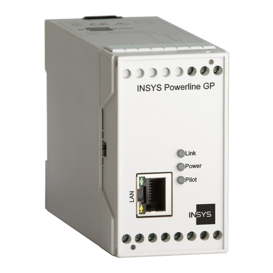
INSYS Powerline GP Display and Control Elements Display and Control Elements Figure 1: LEDs on the front panel Position Description Status LED for Ethernet connection (yellow) Status LED for Ethernet connection (green) Link LED Power LED Pilot LED (pilot coupling status) -
Page 18: Meaning Of The Display Elements
Display and Control Elements INSYS Powerline GP Meaning of the Display Elements Description Display Meaning Status LED (yellow) LED on 100 MBit/s connection LED off No connection or connection with 10 MBit/s Status LED (green) LED on Connected LED blinks Data traffic... -
Page 19: Connections
INSYS Powerline GP Connections Connections Front Panel Connections Figure 2: Connections on the front panel of the device Position Description Ethernet connection Table 5: Connections on the front panel of the device... -
Page 20: Terminal Connections On The Bottom
Connections INSYS Powerline GP Terminal Connections on the Bottom Figure 3: Connections on the bottom of the device Terminal Description Description Reset Reset input Ground 10 ... 60 VDC Power supply 10 V – 60 V DC not connected Pilot In + Input signal pilot line from pilot source Pilot In –... -
Page 21: Terminal Connections On The Top
INSYS Powerline GP Connections Figure 4: Pilot signal connection Terminal Connections on the Top Figure 5: Connections on the top of the device Terminal Description Description 9 – 13 not connected Powerline connection not connected Powerline connection Table 7: Connections on the top of the device... -
Page 22: Function Overview
Charging station (EVSE) and electric vehicle (PEV) communicate using the powerline standard HomePlug GreenPHY™ 1.1 as per ISO/IEC 15118. The requirements for this are described in ISO/IEC 15118-3. The INSYS Powerline GP provides the communication connection between the EVSE controller (as per ISO/IEC 15118-2) and the electric vehicle (PEV). -
Page 23: Assembly
INSYS Powerline GP Assembly Assembly This chapter describes how to mount the INSYS Powerline GP to a DIN rail, connect the power supply, connect the communication line and uninstall it again. Observe the instructions in the "Safety" section of this manual, in particular the "Safety Instructions for Electrical Installation"... - Page 24 Risk of fatal injury from electric shock when touching as well as fire hazard and damage of the product. The INSYS Powerline GP must not be used in wet or damp environments, or in the direct vicinity of water. Install the INSYS Powerline GP at a dry location, protected from water spray.
- Page 25 Position the device at the DIN rail as seen in the following diagram. There are two snap-in hooks at the upper and lower edge of the DIN rail groove of INSYS Powerline GP. Hook the upper one into place behind the upper edge of the DIN rail.
- Page 26 Assembly INSYS Powerline GP Lift the INSYS Powerline GP perpendicular to the DIN rail until the two lower, flexible snap-in hooks engage in the DIN rail. The INSYS Powerline GP is now readily mounted. Connecting the power supply ...
- Page 27 The INSYS Powerline GP is disconnected from the power supply. Removing the device from the DIN rail How to uninstall the INSYS Powerline GP from a DIN rail in a switch cabinet: You will need a Phillips screwdriver with a 4.5 mm blade.
- Page 28 The plastic spring of the snap-in hook is stretched. While you hold the plastic spring apart with the lower snap-in hooks, pull the INSYS Powerline GP away from the DIN rail. Un-hook the INSYS Powerline GP and take it off perpendicularly to the DIN rail. ...
-
Page 29: Function
If a different firmware than the one provided by INSYS is used or the firmware is modified, any claims for warranty and support will cease to exist. Configuration The configuration of the INSYS Powerline GP can be done using two different tool kits: • devolo dLAN SDK under Windows •... - Page 30 Resetting the device Proceed as follows to perform the respective procedures: • Reading out the status information How to read out the status information of a INSYS Powerline GP. The MAC address of the device is known (here: 00:05:B6:01:2F:FC).
- Page 31 – The PIB file will be uploaded to the device. • Resetting the Device How to reset an INSYS Powerline GP. The MAC address of the device is known (here: 00:05:B6:01:2F:FC). The MAC address of the interface to which the device is connected is known (here: 00:1B:21:A0:90:E0).
-
Page 32: 9.2.2 Configuration Using Open-Plc-Utils
INSYS Powerline GP 9.2.2 Configuration using open-plc-utils The configuration of the INSYS Powerline GP takes place on command line level via editing the PIB file according to the following scheme: 1. Download PIB file from the device and store it locally 2. - Page 33 INSYS Powerline GP Function • Reading out the status information How to read out the status information of a INSYS Powerline GP. The MAC address of the device is known (here: 00:05:B6:03:2E:DE). The Ethernet network interface to which the device is connected is known (here: 2).
- Page 34 Function INSYS Powerline GP • Writing the PIB file How to upload the PIB file with the name "new.pib" to a device. The MAC address of the device is known (here: 00:05:B6:03:2E:DE). The Ethernet network interface to which the device is connected is known (here: 2).
-
Page 35: Slac Protocol
INSYS Powerline GP Function SLAC Protocol The modem INSYS Powerline GP implements the SLAC protocol as per ISO/IEC15118-3 for the charging station side (EVSE). Objective of the SLAC proto- col is the association between PEV (Plug-In Electronic Vehicle) and EVSE. Upon successful association, PEV and EVSE will establish an AVLN (AV Logical Network). -
Page 36: 9.3.1 Slac Interface
INSYS Powerline GP 9.3.1 SLAC Interface The INSYS Powerline GP is able to accept commands via the Ethernet interface. Outgoing messages are also sent via the Ethernet interface. The recipient of out- going messages will be referred to as Higher-level Entity (HLE) in the following. - Page 37 Function 9.3.1.2 Terminating SLAC An existing connection can be terminated in the following ways. The INSYS Powerline GP will cease to participate in any SLAC association and ter- minate a possibly existing connection with the command HC_STOP_LIS- TEN_FOR_SLAC_ASSN.IND. Figure 7: Sequence diagram: Terminating SLAC with HC_STOP_LISTEN_FOR_SLAC_ASSN.IND...
- Page 38 Function INSYS Powerline GP The INSYS Powerline GP will cease to participate in any SLAC association and ter- minate a possibly existing connection with the command D_LINK_TERMINATE.re- quest RESETUP no. Figure 8: Sequence diagram: Terminating SLAC with D_LINK_TERMINATE.REQ Resetup no...
- Page 39 INSYS Powerline GP Function The INSYS Powerline GP will terminate a possibly existing connection and allow a new SLAC association with the command D_LINK_TERMINATE.request RESETUP yes. Figure 9: Sequence diagram: Terminating SLAC with D_LINK_TERMINATE.REQ Resetup yes...
- Page 40 The following status messages are event-based and will be sent to the HLE upon the respective event. The INSYS Powerline GP will inform the HLE that it is ready to perform a SLAC as- sociation with the status message HC_STATUS.IND. Before a SLAC association can be performed, it generates a random NMK (Network Membership Key) and thus sets the access data for the next AVLN.
- Page 41 INSYS Powerline GP Function The INSYS Powerline GP informs the HLE that no SLAC association has been achieved with the status message Timeout_TT_EVSE_SLAC_init. It will not respond on any SLAC requests following this timeout. Figure 11: Sequence diagram: Status message Timeout_TT_EVSE_SLAC_init...
- Page 42 Function INSYS Powerline GP The INSYS Powerline GP will inform the HLE that it has sent an Attenuation Profile to a PEV, but has not received an answer from it, with the status message Timeout_TT_EVSE_match_session. Figure 12: Sequence diagram: Status message Timeout_TT_EVSE_match_session...
- Page 43 INSYS Powerline GP Function The INSYS Powerline GP will inform the HLE that an association between PEV and EVSE has been made, but no AVLN could be established, with the status message Timeout_TT_EVSE_match_join. Figure 13: Sequence diagram: Status message Timeout_TT_EVSE_match_join...
- Page 44 Function INSYS Powerline GP 9.3.1.4 Status Request The command HC_STATUS.REQ Req_DLinkStatus allows to check, whether an AVLN exists between the INSYS Powerline GP and a PEV. Figure 14: Sequence diagram: Status request HC_STATUS.REQ...
-
Page 45: 9.3.2 Commands
INSYS Powerline GP Function 9.3.2 Commands The commands are transmitted in basic Ethernet frames as per IEEE 802.3 and are structured as follows. 9.3.2.1 HC_LISTEN_FOR_SLAC_ASSN Set System State to Unmatched. The device will listen for SLAC requests. Prerequisite: System State is Unoccupied... - Page 46 Function INSYS Powerline GP 9.3.2.2 HC_STOP_LISTEN_FOR_SLAC_ASSN Set System State to Unoccupied and stop all possible running Associations. Prerequisite: System State shall not be Unoccupied Field Field size Definition (octets) Dest. MAC Powerline GP MAC Source MAC HLE MAC Ethertype Ethertype = 0xabba...
- Page 47 INSYS Powerline GP Function 9.3.2.3 HC_ATTEN_CALC_RESULT Status message that includes an Attenuation Profile. Every time the device sends an Attenuation Profile to a PEV, the same profile will also be sent to the HLE. Field Field size Definition (octets) Dest. MAC...
- Page 48 Function INSYS Powerline GP 9.3.2.5 D_LINK_TERMINATE Terminates a current SLAC Association. If Resetup is yes, the device will listen again for SLAC requests. If Resetup is no, the device will remain in Unmatched state. Prerequisite: System State is Matched or Unmatched...
- Page 49 INSYS Powerline GP Function 9.3.2.6 HC_STATUS Indication Indicates several Status Information. Field Field size Definition (octets) Dest. MAC HLE MAC Source MAC Powerline GP MAC Ethertype Ethertype = 0xabba Reserved Reserved = 0x00 Type HC_STATUS.IND Type = 0x0b09 0x00 = Timeout_TT_EVSE_SLAC_init...
- Page 50 Function INSYS Powerline GP Confirmation of HC_STATUS.REQ Status Information from the device Field Field size Definition (octets) Dest. MAC Source MAC of HC_STATUS.REQ Source MAC Powerline GP MAC Ethertype Ethertype = 0xabba Reserved Reserved = 0x00 Type HC_STATUS.CNF Type = 0x0b0b Previous req.
- Page 51 9.3.2.8 AttenRxEVSE This value stands for the attenuation in the charging station between the charging coupling and the Pilot-Out of the INSYS Powerline GP (without charging cable). At- tenRxEVSE has the same format as an Attenuation Profile, which is described in the Homeplug GreenPHY specification 1.1 (ATTEN_PROFILE).
-
Page 52: Maintenance, Repair And Troubleshooting
Repair Send defect devices with detailed failure description to the source of supply of your device. If you have purchased the device directly from INSYS icom, send the device to: INSYS MICROELECTRONICS GmbH, Hermann-Köhl-Str. 22, 93049 Regensburg. Before dispatching the device: •... -
Page 53: Waste Disposal
INSYS Powerline GP Waste Disposal Waste Disposal 11.1 Repurchasing of Legacy Systems According to the new WEEE guidelines, the repurchasing and recycling of legacy systems for our clients is regulated as follows: Please send those legacy systems to the following address, carriage prepaid:... -
Page 54: Declaration Of Conformity
Declaration of Conformity INSYS Powerline GP Declaration of Conformity This device complies with the requirements set out in the Council Directive on the Approximation of the Laws of the Member States relating to Electromagnetic Com- patibility 2004/108/EC and the Council Directive relating to Low Voltage 2006/95/EC. -
Page 55: Licenses
INSYS Powerline GP Licenses Licenses The source code of the firmware of this device is covered by various licenses. FreeRTOS The FreeRTOS.org source code is licensed by the modified GNU General Public Li- cense (GPL) text provided below. The FreeRTOS download also includes demo ap- plication source code, some of which is provided by third parties AND IS LICENSED SEPARATELY FROM FREERTOS.ORG. - Page 56 Licenses INSYS Powerline GP GNU GENERAL PUBLIC LICENSE TERMS AND CONDITIONS FOR COPYING, DISTRIBUTION AND MODIFICATION 0. This License applies to any program or other work which contains a notice placed by the copyright holder saying it may be distributed under the terms of this General Public License.
- Page 57 INSYS Powerline GP Licenses such an announcement, your work based on the Program is not required to print an announcement.) These requirements apply to the modified work as a whole. If identifiable sec- tions of that work are not derived from the Program, and can be reasonably...
- Page 58 Licenses INSYS Powerline GP which the executable runs, unless that component itself accompanies the exe- cutable. If distribution of executable or object code is made by offering access to copy from a designated place, then offering equivalent access to copy the source...
- Page 59 INSYS Powerline GP Licenses It is not the purpose of this section to induce you to infringe any patents or other property right claims or to contest validity of any such claims; this section has the sole purpose of protecting the integrity of the free software distribution system, which is implemented by public license practices.
- Page 60 Licenses INSYS Powerline GP NO WARRANTY 11. BECAUSE THE PROGRAM IS LICENSED FREE OF CHARGE, THERE IS NO WARRANTY FOR THE PROGRAM, TO THE EXTENT PERMITTED BY APPLICA- BLE LAW. EXCEPT WHEN OTHERWISE STATED IN WRITING THE COPYRIGHT HOLDERS AND/OR OTHER PARTIES PROVIDE THE PROGRAM "AS IS" WITH-...
- Page 61 INSYS Powerline GP Licenses This program is distributed in the hope that it will be useful, but WITHOUT ANY WARRANTY; without even the implied warranty of MERCHANTABILITY or FITNESS FOR A PARTICULAR PURPOSE. See the GNU General Public License for more details.
- Page 62 Licenses INSYS Powerline GP The FreeRTOS GPL Exception Text: Any FreeRTOS source code, whether modified or in it's original release form, or whether in whole or in part, can only be distributed by you under the terms of the GNU General Public License plus this exception. An independent module is a mod- ule which is not derived from or based on FreeRTOS.
- Page 63 INSYS Powerline GP Licenses Swedish Institute of Computer Science * Copyright (c) 2001, Swedish Institute of Computer Science. * All rights reserved. * Redistribution and use in source and binary forms, with or without * modification, are permitted provided that the following conditions * are met: * 1.
- Page 64 Licenses INSYS Powerline GP Adam Dunkels * Copyright (c) 2001-2003, Adam Dunkels. * All rights reserved. * Redistribution and use in source and binary forms, with or without * modification, are permitted provided that the following conditions * are met: * 1.
- Page 65 INSYS Powerline GP Licenses devolo AG * Copyright (c) 2012, devolo AG, Aachen, Germany. * All rights reserved. * This Software is part of the devolo GreenPHY-SDK. * Usage in source form and redistribution in binary form, with or without...
- Page 66 Licenses INSYS Powerline GP dLAN® SDK Terms of Use The software included in this package forms the dLAN® SDK. Copyright (c) 2013, devolo AG, Aachen, Germany. All rights reserved. Usage of the dLAN® SDK and redistribution in binary form are permitted provided that the following conditions are met: 1.
- Page 67 INSYS Powerline GP Licenses Copyright (c) 1999 - 2005 NetGroup, Politecnico di Torino (Italy). Copyright (c) 2005 - 2010 CACE Technologies, Davis (California). All rights reserved. Redistribution and use in source and binary forms, with or without modification, are permitted provided that the following conditions are met: 1.
- Page 68 Licenses INSYS Powerline GP 4. Neither the name of the University nor the names of its contributors may be used to endorse or promote products derived from this software without specific prior written permission. THIS SOFTWARE IS PROVIDED BY THE INSTITUTE AND CONTRIBUTORS ``AS IS''...
- Page 69 INSYS Powerline GP Licenses EXEMPLARY, OR CONSEQUENTIAL DAMAGES (INCLUDING, BUT NOT LIMITED TO, PROCUREMENT OF SUBSTITUTE GOODS OR SERVICES; LOSS OF USE, DATA, OR PROFITS; OR BUSINESS INTERRUPTION) HOWEVER CAUSED AND ON ANY THEORY OF LIABILITY, WHETHER IN CONTRACT, STRICT LIABILITY, OR TORT...
- Page 70 Licenses INSYS Powerline GP WHATSOEVER RESULTING FROM LOSS OF USE, DATA OR PROFITS, WHETHER IN AN ACTION OF CONTRACT, NEGLIGENCE OR OTHER TORTIOUS ACTION, ARISING OUT OF OR IN CONNECTION WITH THE USE OR PERFORMANCE OF THIS SOFT- WARE. Portions Copyright (C) 1995, 1996, 1997, 1998, and 1999 WIDE Project. All rights reserved.
- Page 71 INSYS Powerline GP Licenses Redistribution and use in source and binary forms, with or without modification, are permitted provided that the following conditions are met: - Redistributions of source code must retain the above copyright notice, this list of conditions and the following disclaimer.
-
Page 72: Tables And Diagrams
Tables and Diagrams INSYS Powerline GP Tables and Diagrams 14.1 List of Tables Table 1: Physical Features ..................15 Table 2: Technological Features ................16 Table 3: Description of the LEDs on the front panel ..........17 Table 4: Meaning of the LED displays ..............18 Table 5: Connections on the front panel of the device .......... -
Page 73: List Of Diagrams
INSYS Powerline GP Tables and Diagrams 14.2 List of Diagrams Figure 1: LEDs on the front panel ................17 Figure 2: Connections on the front panel of the device .......... 19 Figure 3: Connections on the bottom of the device ..........20 Figure 4: Pilot signal connection ................ -
Page 74: Index
Index INSYS Powerline GP Index Additional information ....... 9 Overcurrent ........13 Alternative results ......9 Overvoltage ....... 13, 16 Ambient temperature ...... 16 Overvoltage protection ....13, 16 Checkmark ........9 Permissible limit ......10 Connection ........24 Personnel ........11 Defects liability terms ......
Need help?
Do you have a question about the Powerline GP and is the answer not in the manual?
Questions and answers