Panasonic AK-HRP1000G Operating Instructions Manual
Remote operation panel
Hide thumbs
Also See for AK-HRP1000G:
- Operating instructions manual (43 pages) ,
- Operating manual (40 pages) ,
- Operation manual (34 pages)
Table of Contents
Advertisement
Quick Links
Download this manual
See also:
Operating Manual
Advertisement
Table of Contents

Related Manuals for Panasonic AK-HRP1000G


Summary of Contents for Panasonic AK-HRP1000G
- Page 1 Operating Instructions Remote Operation Panel AK-HRP1000G Model No. Please carefully read this manual, and save this manual for future use. Before using this product, be sure to read “Read this first!” (pages 2 to 4) . ENGLISH...
-
Page 2: Read This First
Read this first! Read this first! WARNING: CAUTION • To reduce the risk of fire, do not expose this equipment to RISK OF ELECTRIC SHOCK rain or moisture. DO NOT OPEN • To reduce the risk of fire, keep this equipment away from all liquids. - Page 3 Read this first! IMPORTANT SAFETY INSTRUCTIONS 1) Read these instructions. 2) Keep these instructions. 3) Heed all warnings. 4) Follow all instructions. 5) Do not use this apparatus near water. 6) Clean only with dry cloth. 7) Do not block any ventilation openings. Install in accordance with the manufacturer’s instructions. 8) Do not install near any heat sources such as radiators, heat registers, stoves, or other apparatus (including amplifiers) that produce heat.
- Page 4 AEEE Complies with Directive of Turkey. Note: The rating plate (serial number plate) is on the bottom of the unit. Manufactured by: Panasonic Corporation, Osaka, Japan Importer’s name and address of pursuant to EU rules: Panasonic Marketing Europe GmbH Panasonic Testing Centre...
-
Page 5: Table Of Contents
Table of Contents Read this first! Displaying and setting the master gain (M.GAIN) Shutter (SHUTTER) Introduction Displaying and setting the shutter (SHUTTER) How to View This Manual Master pedestal (M.PED) About trademarks and registered trademarks Displaying and setting the master pedestal (M.PED) About copyright Illustrations and screen displays featured in the manual Iris (IRIS) - Page 6 30 SYSTEM CAM 31 SYSTEM CCU 32 CAMERA MENU CONTROL 33 CCU MENU CONTROL 34 ROP SETTING 35 CONNECT SETTING 36 ROP IP SETTING 37 CAMERA IP SETTING 38 SD CARD STORE 39 SD CARD LOAD 40 REFERENCE 41 AUTO IRIS SETTING 42 HDR-PAINT 43 LENS CONTROL Software...
-
Page 7: Introduction
For the purposes of this manual, the model numbers of the units are given as listed in the table below. Model number of unit Model number given in manual AK-HC5000G AK-HC5000 AK-HC5000GS AK-UC3000G AK-UC3000 AK-UC3000GS AK-UC4000G AK-UC4000 AK-UC4000GS AK-HRP1000G AK-HRP1000 AK-UCU500 AK-UCU500 AK-UCU500S AK-UCU600 AK-UCU600 AK-UCU600S - 7 -... -
Page 8: Overview
Introduction Overview This unit is a remote operation panel for controlling a studio handy camera (AK-HC5000; sold separately, AK-UC3000/AK-UC4000; sold separately) and a camera control unit (AK-UCU500/AK-UCU600; sold separately). Use a dedicated optical fiber multi cable to connect a studio handy camera to a camera control unit and use an ROP cable or IP connection to connect this unit to the camera control unit. -
Page 9: Notice
Disclaimer of warranty IN NO EVENT SHALL Panasonic Corporation BE LIABLE TO ANY PARTY OR ANY PERSON, EXCEPT FOR REPLACEMENT OR REASONABLE MAINTENANCE OF THE PRODUCT, FOR THE CASES, INCLUDING BUT NOT LIMITED TO BELOW: ANY DAMAGE AND LOSS, INCLUDING WITHOUT LIMITATION, DIRECT OR INDIRECT, SPECIAL, CONSEQUENTIAL OR EXEMPLARY, ARISING OUT OF OR RELATING TO THE PRODUCT;... -
Page 10: Restrictions On Use
4 GB to 32 GB SDXC memory cards are not supported. For the latest information not described in the Operating Instructions, refer to the following website. https://pro-av.panasonic.net/ Observe the following points when using and storing this unit. Avoid high temperature and humidity. -
Page 11: Features
The supplied ROP Setup Software can be used to set the camera connections. *1: Power over Ethernet. Referred to as "PoE" in this manual. *2: For details on PoE power supply devices for which operation has been verified, consult your dealer or Panasonic representative. - 11 -... -
Page 12: Accessories
Introduction Accessories After unpacking the product, dispose of the packaging material appropriately. CD-ROM……………1 Easy IP Setup Software ROP Setup Software - 12 -... -
Page 13: Precautions For Use
Introduction Precautions for Use In addition to the safety precautions given in “Read this first!”, also observe the following instructions. Handle carefully Do not drop the unit or expose it to strong impacts or vibrations. Do not carry the unit by the [IRIS] lever. Doing so may cause a fail- ure or accident. -
Page 14: Precautions For Installation
Introduction Precautions for Installation In addition to the safety precautions given in “Read this first!”, also observe the following instructions. Be sure to ask your dealer to perform the installation and connection work for the unit. Cable connections Be sure to use dedicated ROP cables (Hirakawa Hewtech Corp. 20379-FG-SV-10 cables or equivalent). If the unit will not be used for an extended period of time, disconnect the ROP cables to save electricity. -
Page 15: Installing And Removing Rack Mount Brackets
Introduction Installing and removing rack mount brackets The unit is shipped from the factory with the rack mount brackets installed. The customer can remove the four screws that hold the rack mount brackets in place using a Phillips screwdriver. A. Rack mount bracket B. -
Page 16: Connection
Connection Connection Operation Modes Operation mode setting procedure In the factory default state, connect the CCU to the unit and then set the operation mode. Connect the CCU to the unit in the factory default state. Operation in serial connection Operation in IP connection 1. -
Page 17: System Connection Configuration
Connection System Connection Configuration The unit can be connected to a CCU via a serial connection or IP connection. Up to 99 CCUs can be controlled. Only one CCU can be connected via a serial connection. A configuration with one serial connection and 98 IP connections is possible. CCU connections Serial connection Connection example:... - Page 18 Connection IP connection Personal computer AK-UCU500 AK-UCU500 LAN cable (straight cable) PoE-compatible switching hub (100base-TX) LAN cable (straight cable) Max.100 m (328.1 ft) AK-HRP1000 *1: The CCU does not support PoE. 1. Connect the <LAN> connector on this unit to the <LAN> connector on the CCU rear panel using a LAN cable (sold separately).
-
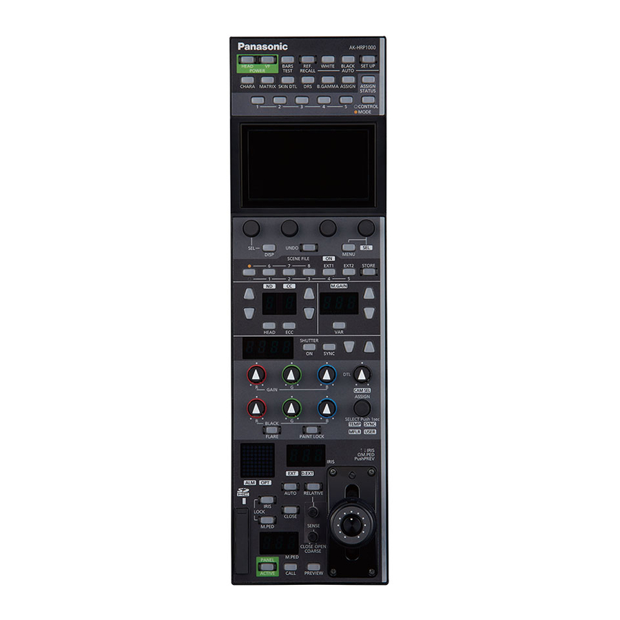
Page 19: Parts And Their Functions
Parts and their functions Parts and their functions Front panel 1 10 11 12 13 [POWER HEAD] button Use this button to control camera power remotely. However, it will not function unless the CCU and the camera are turned on. Each press of the button turns the power of the camera on or off. - Page 20 Parts and their functions [AUTO WHITE] button Use this button to perform auto white balance adjustment. Status displays Indicates that the auto white balance adjustment has started. Flashing: Warns that the automatic white balance adjustment ended without being completed. When highlights and lowlights are lost, white balance is returned to its previous value.
- Page 21 Parts and their functions [ASSIGN] button Use this button to enable or disable the menu function assigned to the button. Status displays When “FLARE”, “GAMMA”, “KNEE”, “W.CLIP”, “HD.D”, “UHD.D”, or “SD.D” are assigned to the buttons Off: When functions other than the above are assigned Off: Set the function assigned to the [ASSIGN] button in [ROP SETTING] >...
-
Page 22: Front Panel 2
Parts and their functions Front panel 2 [ASSIGN STATUS] button Use this button to display the ASSIGN status screen. The functions assigned to the [1] to [5] (CONTROL/MODE) buttons and [ASSIGN] button are displayed on the LCD panel. When you press this button while the menu screen is displayed, the ASSIGN status screen will not appear. -
Page 23: Front Panel 3
Parts and their functions Front panel 3 LCD panel This panel displays the menu screen or status screen. [MENU] dial Use these dials to perform operations according to the menu items displayed on the LCD panel. [EXIT] button Use this button to return to the previous menu level. [UNDO] button Use this button to restore the values controlled during the setting operation to the values prior to control. -
Page 24: Front Panel 4
Parts and their functions Front panel 4 [ON] indicator (SCENE FILE) This indicator is lit when a scene file is selected. Status displays A scene file is selected. Off: A scene file is not selected. Scene file page switching but- Use this button to switch between scene file pages 1 to 5 and 6 to 8 and between EXT1 and 2. -
Page 25: Front Panel 5
Parts and their functions Front panel 5 [ND] indicator This indicator indicates the ND filter setting status. Status displays Lit green: Standard position set in the ROP menu. Lit Orange: Updated from the standard position set in the ROP menu. The standard position of the ND filter can be set in [ROP SETTING] >... - Page 26 Parts and their functions [M.GAIN] indicator This displays the master gain configuration status. Status displays Lit green: Standard position set in the ROP menu. Lit Orange: Updated from the standard position set in the ROP menu. The standard position of the master gain can be set in [ROP SETTING] > [STD POSITION M.GAIN] in the ROP menu.
-
Page 27: Front Panel 6
Parts and their functions Front panel 6 [SHUTTER] display The display shows the shutter value. [ON] button (SHUTTER) Turns the shutter on or off. Status displays Off: [SYNC] button (SHUTTER) Use this button switch between the shutter and sync shutter. Status displays Sync shutter Off:... -
Page 28: Front Panel 7
Parts and their functions Front panel 7 8 10 11 9 [GAIN R], [GAIN G], and [GAIN Use these control dials to adjust the white balance (R, G, and B). Turning a dial changes the gain control value in the status screen. B] dials The setting values can be viewed in the [GAIN] area of the LCD panel (status screen). - Page 29 Parts and their functions [DTL] dial Use this dial to adjust the detail level. The setting values can be viewed in the [DTL] area of the LCD panel (status screen). You can configure whether to perform [DTL] adjustment for UHD, HD, or SD under [ROP SETTING] > [DTL VOL] of the ROP menu.
-
Page 30: Front Panel 8
Parts and their functions Front panel 8 [EXT] indicator This indicator lights to warn that the lens extender is set to something other than 1x. Status displays The lens extender is set to something other than 1x. Off: This indicates that the lens extender is not being used or that it is not available. - Page 31 Parts and their functions [COARSE] dial Adjusts how much the iris is opened or closed when the [IRIS] dial is moved. Dial operation This is enabled only when [IRIS LEV MODE] on the [ROP SETTING] menu is set to “ABS”. Turn right (clockwise) (OPEN): The [IRIS] dial will operate at its most sens- itive range.
- Page 32 Parts and their functions [M.PED LOCK] button Use this button to disable (lock) master pedestal operation. Lock range Status displays Off: Master pedestal can be controlled. Lit red: Operation is disabled (locked). When the [M.PED] dial is returned to the lock position, the button turns off and normal control becomes possible.
-
Page 33: Front Panel 9
Parts and their functions Front panel 9 Camera number/tally display This display shows the camera number information and tally information. [ALM] indicator This is the camera and CCU warning indicator lamp. Consult your dealer if a failure occurs. The indicator lights red to indicate when the camera and CCU optical reception level is not strong enough, when a data error has occurred in the CCU optical transmission/reception section, and when a fan error or temperature error has been occurred on the camera or CCU. - Page 34 Parts and their functions [PREVIEW] button Use this button to output a preview signal from the preview connector. Pressing the [IRIS] lever also outputs the preview signal. Status displays Preview output is On Off: Preview output is Off Memory card slot Insert a memory card into this slot.
-
Page 35: Connectors
Parts and their functions Connectors <CCU> connector This connector is for serial connections to the CCU. <LAN> connector Use a LAN cable to connect to a CCU or personal computer that supports IP connections. <PREVIEW> connector This connector outputs preview signals. <SIGNAL GND>... -
Page 36: Adjustment And Settings
Adjustment and settings Adjustment and settings Auto Setup Starting auto setup Before starting auto setup Choose [SYSTEM CAM] > [ASU MODE] in the ROP menu to select “FULL” or “EASY” mode. “ASU MODE” (see page 104) FULL Standard setup based on an outdoor shooting chart EASY Easy setup based on an outdoor shooting chart Align the position of the gray scale wedge with the angle of view in the vertical direction of the viewfinder. -
Page 37: Scene File
Adjustment and settings Scene file Storing and opening scene files Storing scene files You can register the data currently being operated as a scene file. A. [STORE] button B. [1/6], [2/7], [3/8], [4/EXT1], and [5/EXT2] buttons C. Scene file page switching button Operating procedure 1. -
Page 38: Paint Lock
Adjustment and settings PAINT LOCK Using the PAINT LOCK Lock (disable) the paint control operations. The following operations are targets of the paint control lock (PAINT LOCK). [GAIN R], [GAIN G], and [GAIN B] dials (B): White balance adjustment [BLACK R], [BLACK G], and [BLACK B] (C) dials: Pedestal or flare adjustment [DTL] dial (D): Detail enhancer adjustment A. -
Page 39: Nd Filter
Adjustment and settings ND filter Displaying and setting the ND filter The adjustment value of the ND filter is displayed on the [ND] display (B). When the setting value is changed from the standard position set in the ROP menu, the [ND] indicator (A) is orange lit. (The standard pos- ition remains set while the indicator is green lit.) “STD POSITION ND”... -
Page 40: Cc Filter
Adjustment and settings CC filter Displaying and setting the CC filter The adjustment value of the CC filter is displayed on the [CC] display (B). When the setting value is changed from the standard position set in the ROP menu, the [CC] indicator (A) is orange lit. (The standard pos- ition remains set while the indicator is green lit.) “STD POSITION CC”... -
Page 41: Color Temperature (Ecc)
Adjustment and settings Color temperature (ECC) Setting the color temperature (ECC) When the [ECC] button (A) is lit, you can select and change the preset color temperature. You can verify the adjustment value on the status screen. “ECC” (see page 51) A. -
Page 42: Master Gain (M.gain)
Adjustment and settings Master gain (M.GAIN) Displaying and setting the master gain (M.GAIN) The adjustment value of the master gain (M.GAIN) is displayed on the [M.GAIN] display (B). When the setting value is changed from the standard position set in the ROP menu, the [M.GAIN] indicator (A) is orange lit. (The standard position remains set while the indicator is green lit.) “STD POSITION M.GAIN”... -
Page 43: Shutter (Shutter)
Adjustment and settings Shutter (SHUTTER) Displaying and setting the shutter (SHUTTER) You can turn the shutter on or off by pressing the [ON] button (SHUTTER) (A). (The shutter is turned on when the button is lit.) The shutter value is displayed in the [SHUTTER] display (B) and can be adjusted using the [SHUTTER] setting buttons (C). Step shutter adjustment is enabled when the [SYNC] button (SHUTTER) (D) is not lit, and sync shutter adjustment is enabled when the but- ton is lit. -
Page 44: Master Pedestal (M.ped)
Adjustment and settings Master pedestal (M.PED) Displaying and setting the master pedestal (M.PED) The master pedestal (M.PED) setting is displayed on the [M.PED] display (A) when the [M.PED] dial (B) is operated. Adjustment is possible while the [M.PED LOCK] button (C) is off (canceled). A. -
Page 45: Iris (Iris)
Adjustment and settings Iris (IRIS) Displaying and setting the iris (IRIS) Manual adjustment When the auto iris is not on, the iris can be adjusted manually. The iris value is displayed on the [IRIS] display (A). Adjustment is possible while the [AUTO] button (C) is off (AUTO is canceled). Adjustment is possible while the [IRIS LOCK] button (D) is off (iris lock is canceled). - Page 46 Adjustment and settings A. [AUTO] button B. [IRIS] lever Operating procedure 1. Press the [AUTO] button (A) to turn on the button. The auto iris turns on. When the auto iris is on, the convergence level of the iris can be adjusted with the [IRIS] lever (B). Moving it forward adjusts the level in the CLOSE direction and moving it backward adjusts the level in the OPEN direction.
-
Page 47: [Select] Dial
Adjustment and settings [SELECT] dial Using the select dial Use the [SELECT] dial (A) to select and adjust the function of any of [TEMP], [CAM SEL], [SYNC], [USER], and [MFLR]. Indicator Function The value of [COLOR TEMP] can be changed with the dial. TEMP “COLOR TEMP”... -
Page 48: Camera Selection
Adjustment and settings Camera selection Select the camera to be the target for control with the unit. Select the camera after switching to camera selection mode. A. [SELECT] dial B. [CAM SEL] indicator Operating procedure 1. Press the [SELECT] dial (A) for at least approximately 1 second. This allows you to select [TEMP], [CAM SEL], [SYNC], [USER], and [MFLR]. -
Page 49: Status Screen
Status screen Status screen Displaying and operating the status screen The status screen is displayed on the LCD panel of the unit when the ROP menu (REMOTE OPERATION MENU) is not being used (i.e., the menu is turned OFF). A: Displays the functions assigned to each button B to E:... -
Page 50: Items Displayed On The Status Screen
Status screen Items displayed on the status screen OPT LEVEL This displays the optical transmission strength. Display Item CAM RCV Displays the optical transmission/reception strength on the camera side. CCU RCV Displays the optical transmission/reception strength on the CCU side. CAM INFO This displays the camera information. -
Page 51: Assign
Status screen Display Item Displays the currently set scene number. SCENE “Scene file” (see page 37) Displays the ND filter name acquired from the CCU. “ND filter” (see page 39) Displays the CC filter name acquired from the CCU. “CC filter” (see page 40) Displays the current information of [09 ECC] >... -
Page 52: Assign Status Screen
Status screen ASSIGN status screen The items assigned to the [1] to [5] buttons (B) and [ASSIGN] button, and the [USER] indicator can be checked on the LCD panel. Press the [ASSIGN STATUS] button (A) to display the assignments. A. [ASSIGN STATUS] button B. -
Page 53: Rop Menu
ROP menu ROP menu Displaying menus The LCD panel of the unit can be used to operate the ROP menu (REMOTE OPERATION MENU). ROP menu operation is a function that is enabled when the unit is connected to a camera or CCU. Follow the procedure below to display the ROP menu. -
Page 54: Basic Menu Operations
ROP menu Basic menu operations 1. Press the [MENU] button (A). The menu appears on the LCD panel (B). (The cursor is on the first line.) [MENU] button LCD panel 2. Turn the [MENU] dial (C) clockwise to move the cursor. [MENU] dial 3. -
Page 55: Other Menu Operations
ROP menu 4. Turn the [MENU] dial (C) to move the cursor to each setting item. [MENU] dial 5. Turn the [MENU] dial (D) to set the items. Turn the dial at the same position as each item in the screen. [MENU] dial Other menu operations Returning to the menu selection screen... -
Page 56: Rop Menu List
ROP menu ROP menu list “BLACK SHADING” (see page 67) BLACK SHADING WHITE SHADING “WHITE SHADING” (see page 67) FLARE “FLARE” (see page 67) GAMMA “GAMMA” (see page 67) BLACK GAMMA “BLACK GAMMA” (see page 67) “DRS” (see page 67) “WHITE CLIP”... - Page 57 ROP menu “GAIN AWB R” (see page 73) GAIN AWB R GAIN AWB G “GAIN AWB G” (see page 73) GAIN AWB B “GAIN AWB B” (see page 73) 07 RGB GAIN GAIN OFFSET “GAIN OFFSET” (see page 73) “GAIN ABS” (see page 73) GAIN ABS “G GAIN REL”...
- Page 58 ROP menu “GAMMA R” (see page 79) GAMMA R GAMMA MASTER “GAMMA MASTER” (see page 79) GAMMA B “GAMMA B” (see page 79) INITIAL GAMMA “INITIAL GAMMA” (see page 79) “GAMMA MODE” (see page 79) GAMMA MODE “BLACK STRETCH” (see page 79) BLACK STRETCH 13 GAMMA “DYNAMIC LEVEL”...
- Page 59 ROP menu “MASTER DETAIL” (see page 84) MASTER DETAIL DETAIL LV H “DETAIL LV H” (see page 84) DETAIL LV V “DETAIL LV V” (see page 84) PEAK FRQ “PEAK FRQ” (see page 84) “V DETAIL FRQ” (see page 84) V DETAIL FRQ “CRISP”...
- Page 60 ROP menu “MEMORY SELECT” (see page 88) MEMORY SELECT CURSOR “CURSOR” (see page 88) POS H “POS H” (see page 88) POS V “POS V” (see page 88) “SKIN GET” (see page 88) SKIN GET “ZEBRA SWITCH” (see page 88) ZEBRA SWITCH “ZEBRA EFFECT”...
- Page 61 ROP menu “PRESET MATRIX” (see page 95) PRESET MATRIX LINEAR TABLE “LINEAR TABLE” (see page 95) CORRECT TABLE “CORRECT TABLE” (see page 95) COLOR CORRECT “COLOR CORRECT” (see page 95) “SAT” (see page 95) “PHASE” (see page 95) PHASE “SAT G” (see page 95) SAT G “SAT G_CY”...
- Page 62 ROP menu “POSITION1” (see page 99) POSITION1 POSITION2 “POSITION2” (see page 99) POSITION3 “POSITION3” (see page 99) POSITION4 “POSITION4” (see page 99) “POSITION5” (see page 99) 27 SHUTTER SELECT POSITION5 “POSITION6” (see page 99) POSITION6 “POSITION7” (see page 99) POSITION7 “POSITION8”...
- Page 63 ROP menu “FORMAT” (see page 103) FORMAT TALK OFF INCOM1 “TALK OFF INCOM1” (see page 103) TALK OFF INCOM2 “TALK OFF INCOM2” (see page 103) MIC1 GAIN “MIC1 GAIN” (see page 103) “MIC1 LINE LV” (see page 104) MIC1 LINE LV “MIC1 AMP”...
- Page 64 ROP menu “CONTROL(MENU)1” (see page 110) CONTROL(MENU)1 CONTROL(MENU)2 “CONTROL(MENU)2” (see page 110) CONTROL(MENU)3 “CONTROL(MENU)3” (see page 110) CONTROL(MENU)4 “CONTROL(MENU)4” (see page 110) “CONTROL(MENU)5” (see page 110) CONTROL(MENU)5 “MODE(ON/OFF)1” (see page 111) MODE(ON/OFF)1 “MODE(ON/OFF)2” (see page 111) MODE(ON/OFF)2 “MODE(ON/OFF)3” (see page 111) MODE(ON/OFF)3 MODE(ON/OFF)4 “MODE(ON/OFF)4”...
- Page 65 ROP menu “ROP IP ADDRESS” (see page 117) ROP IP ADDRESS ROP PORT “ROP PORT” (see page 117) UPLOAD “UPLOAD” (see page 117) ROP SUBNET MASK “ROP SUBNET MASK” (see page 117) 36 ROP IP SETTING “UPLOAD” (see page 117) UPLOAD “ROP DEFAULT GATEWAY”...
- Page 66 ROP menu “FOCUS” (see page 127) FOCUS FOCUS SPEED “FOCUS SPEED” (see page 127) 43 LENS CONTROL ZOOM “ZOOM” (see page 127) ZOOM SPEED “ZOOM SPEED” (see page 127) “CONTROL SW” (see page 127) CONTROL SW - 66 -...
-
Page 67: Paint Switch
ROP menu 01 PAINT SWITCH The setting values will vary depending on the connected camera. Item Setting details BLACK SHADING Enables or disables black shading (sawtooth waveform or parabolic waveform). WHITE SHADING Enables or disables white shading (sawtooth waveform or parabolic waveform). FLARE Enables or disables the flare. -
Page 68: Shutter Speed
ROP menu 02 SHUTTER SPEED The setting values will vary depending on the connected camera. Item Setting details SHUTTER SPEED Sets the shutter speed for when [SHUTTER MODE] is set to “SHUT”. SHUTTER SYNCHRO Sets the shutter speed for when [SHUTTER MODE] is set to “SYNC”. SHUTTER SW Enables or disables the shutter function. -
Page 69: Black Shading
ROP menu 03 BLACK SHADING The setting values will vary depending on the connected camera. Item Setting details H SAW R Adjusts the black shading gain for R, G, and Bch in the horizontal direction using a sawtooth waveform. H SAW G H SAW B H PARA R Adjusts the black shading gain for R, G, and Bch in the horizontal direction using a parabolic waveform. -
Page 70: Pedestal
ROP menu 04 PEDESTAL The setting values will vary depending on the connected camera. Item Setting details PED R Sets the red correction level for the master pedestal. PED G Sets the green correction level for the master pedestal. PED B Sets the blue correction level for the master pedestal. -
Page 71: Hd Chroma
ROP menu 05 HD CHROMA The control destination differs depending on the unit configuration. When the camera is an AK-UC4000 The control is performed for the camera. When the camera is other than the above When the system format is set to UHD, the control is performed for the CCU. Otherwise, the control is performed for the camera. The setting values will vary depending on the connected camera. -
Page 72: Uhd Chroma
ROP menu 06 UHD CHROMA The control destination differs depending on the unit configuration. When the camera is an AK-UC4000 The control is performed for the camera. When the camera is other than the above The control is performed for the CCU. The setting values will vary depending on the connected camera. -
Page 73: Rgb Gain
ROP menu 07 RGB GAIN The setting values will vary depending on the connected camera. Item Setting details GAIN AWB R Sets the red correction level for the gain. GAIN AWB G Sets the green correction level for the gain. GAIN AWB B Sets the blue correction level for the gain. -
Page 74: Color Temp
ROP menu 08 COLOR TEMP The setting values will vary depending on the connected camera. Item Setting details COLOR TEMP Set color temperature settings. GAIN R Sets the red correction level for the color temperature. AXIS G Sets the green correction level for the color temperature. GAIN B Sets the blue correction level for the color temperature. -
Page 75: Ecc
ROP menu 09 ECC The setting values will vary depending on the connected camera. Item Setting details COLOR TEMP Sets the color temperature when [COLOR TEMP SW] is set to “ON”. An arrow will appear on the right if the value is too high or low. GAIN R Sets the red correction level for the color temperature. -
Page 76: Cam User Sw Temp
ROP menu 10 CAM USER SW TEMP The setting values will vary depending on the connected camera. Item Setting details COLOR Sets the color temperature for when “C.TEMP” is assigned to the [USER 1], [USER 2], [USER 3], or [USER 4] button on the TEMP camera and the function is enabled. -
Page 77: White Shading
ROP menu 11 WHITE SHADING The setting values will vary depending on the connected camera. Item Setting details H SAW R Adjusts the white shading gain for R, G, and Bch in the horizontal direction using a sawtooth waveform. H SAW G H SAW B H PARA R Adjusts the white shading gain for R, G, and Bch in the horizontal direction using a parabolic waveform. -
Page 78: Flare
ROP menu 12 FLARE The setting values will vary depending on the connected camera. Item Setting details FLARE R Adjusts the Rch flare. FLARE G Adjusts the Gch flare. FLARE B Adjusts the Bch flare. M.FLARE Adjusts the master flare. FLARE Enables or disables flare correction. -
Page 79: Gamma
ROP menu 13 GAMMA The setting values will vary depending on the connected camera. Item Setting details GAMMA R Adjusts the red gamma characteristic for the master gamma. GAMMA MASTER Adjusts the gamma characteristic. GAMMA B Adjusts the blue gamma characteristic for the master gamma. INITIAL GAMMA Sets the rising slope for the gamma. -
Page 80: Black Gamma
ROP menu 14 BLACK GAMMA The setting values will vary depending on the connected camera. Item Setting details BLACK GAMMA R Adjusts the red gamma characteristic near black for the master gamma. BLACK GAMMA MASTER Adjusts the gamma characteristic near black. BLACK GAMMA B Adjusts the blue gamma characteristic near black for the master gamma. -
Page 81: Knee
ROP menu 15 KNEE The setting values will vary depending on the connected camera. Item Setting details POINT R Adjusts the red knee point for [POINT MASTER]. POINT MASTER Sets the knee point position. POINT B Adjusts the blue knee point for [POINT MASTER]. SLOPE R Adjusts the red knee slope for [SLOPE MASTER]. -
Page 82: White Clip
ROP menu 16 WHITE CLIP The setting values will vary depending on the connected camera. Item Setting details WHITE CLIP LEVEL R Adjusts red for [WHITE CLIP LEVEL MASTER]. WHITE CLIP LEVEL MASTER Set the white clip level. WHITE CLIP LEVEL B Adjusts blue for [WHITE CLIP LEVEL MASTER]. -
Page 83: Drs
ROP menu 17 DRS The setting values will vary depending on the connected camera. Item Setting details EFFECT Sets the compression level for high-brightness areas of the dynamic range stretcher function. Higher values increase the DEPTH compression level for high-brightness areas. Enables or disables the dynamic range stretcher function. -
Page 84: Hd Detail
ROP menu 18 HD DETAIL The control destination differs depending on the unit configuration. When the camera is an AK-UC4000 The control is performed for the camera. When the camera is other than the above When the system format is set to UHD, the control is performed for the CCU. Otherwise, the control is performed for the camera. The setting values will vary depending on the connected camera. - Page 85 ROP menu Item Setting details DETAIL GAIN ( - ) Changes the detail gain level in the - (down) direction DETAIL CLIP+ Adjusts detail clipping to minimize scintillation resulting from excessive detail application. DETAIL CLIP- This limits the length of the undershoot portion of the detail edge component. KNEE APERTURE Adjusts the knee aperture level.
-
Page 86: Uhd Detail
ROP menu 19 UHD DETAIL The control destination differs depending on the unit configuration. When the camera is an AK-UC4000 The control is performed for the camera. When the camera is other than the above The control is performed for the CCU. The setting values will vary depending on the connected camera. -
Page 87: Sd Detail
ROP menu 20 SD DETAIL The control destination differs depending on the unit configuration. When the camera is an AK-UC4000 The fixed value is displayed. The setting cannot be changed. When the camera is other than the above The control is performed for the CCU. Otherwise, the control is performed for the camera. The setting values will vary depending on the connected camera. -
Page 88: Hd Skin Tone Dtl
ROP menu 21 HD SKIN TONE DTL The control destination differs depending on the unit configuration. When the camera is an AK-UC4000 The control is performed for the camera. When the camera is other than the above When the system format is set to UHD, the control is performed for the CCU. Otherwise, the control is performed for the camera. The setting values will vary depending on the connected camera. - Page 89 ROP menu Item Setting details I CENTER Sets the center position (area to which skin tone is applied) on the I axis. I WIDTH Sets the width of the area to which skin tone is applied on the I axis using the [I CENTER] setting as the cen- ter.
-
Page 90: Uhd Skin Tone Dtl
ROP menu 22 UHD SKIN TONE DTL The control destination differs depending on the unit configuration. When the camera is an AK-UC4000 The control is performed for the camera. When the camera is other than the above The control is performed for the CCU. The setting values will vary depending on the connected camera. - Page 91 ROP menu Item Setting details SKIN TONE Removes very faint noise components from detail components in skin tone areas. CRISP I CENTER Sets the center position (area to which skin tone is applied) on the I axis. I WIDTH Sets the width of the area to which skin tone is applied on the I axis using the [I CENTER] setting as the center. Q WIDTH Expands the width of skin tone areas in a range from 0 to 255.
-
Page 92: Linear Matrix
ROP menu 23 LINEAR MATRIX The setting values will vary depending on the connected camera. Item Setting details PRESET MATRIX Sets the preset matrix. LINEAR TABLE Selects the linear matrix table. COLOR CORRECT Selects the color correction table. MATRIX(R-G) P Adjusts the linear matrix between red and green. - Page 93 ROP menu Item Setting details MATRIX Enables or disables the matrix function. COLOR CORRECT Enables or disables the 12-axis color correction function. LINEAR MATRIX Enables or disables the linear matrix function. - 93 -...
-
Page 94: Color Correction
ROP menu 24 COLOR CORRECTION The setting values will vary depending on the connected camera. - 94 -... - Page 95 ROP menu Item Setting details PRESET MATRIX Enables or disables the linear matrix function. LINEAR TABLE Selects the linear matrix table. CORRECT TABLE Selects the color correction table. COLOR CORRECT Selects the color component in 12 AXIS matrix memory to adjust. Adjusts the saturation of the color component selected in [COLOR CORRECT].
- Page 96 ROP menu Item Setting details PHASE G Adjusts the color phase of color components in 12 AXIS matrix memory. When [COLOR CORRECT] is set to “OFF”, the adjustment effects will not be applied. PHASE G_CY PHASE CY PHASE CY_B PHASE B PHASE B_MG PHASE MG PHASE MG_R...
-
Page 97: Skin Correction
ROP menu 25 SKIN CORRECTION The setting values will vary depending on the connected camera. Item Setting details SKIN AREA HUE Finely adjusts the hue of the skin area. SKIN AREA TONE Finely adjusts the tone of the skin area. SKIN AREA SW Enables or disables the fine adjustment function for near skin tone color. -
Page 98: Dnr
ROP menu 26 DNR The setting values will vary depending on the connected camera. Item Setting details DNR LEVEL Sets the level for the noise reduction. DNR SW Enables/disables the noise reduction function. - 98 -... -
Page 99: Shutter Select
ROP menu 27 SHUTTER SELECT The setting values will vary depending on the connected camera. Item Setting details POSITION1 Sets the shutter speed for [POSITION1] to [POSITION8]. POSITION2 POSITION3 POSITION4 POSITION5 POSITION6 POSITION7 POSITION8 SHUTTER OFF Selects whether to include shutter OFF when switching the shutter position. - 99 -... -
Page 100: Lens File/Edit
ROP menu 28 LENS FILE/EDIT The setting values will vary depending on the connected camera. Item Setting details MODE Saves the current lens file in the camera (STORE) or loads a lens file stored in the camera (LOAD). FILE No. Selects the file. - Page 101 ROP menu Item Setting details FILE NAME Displays the file name of the file number specified in [FILE No.]. The file name can be changed when [MODE] is set to “STORE”. Use [MENU] dials 1 and 2 to change the file name. [MENU] dial 1 (far left): Selects the character.
-
Page 102: Monitor
ROP menu 29 MONITOR The setting values will vary depending on the connected CCU. Item Setting details MONITOR R Turns the R monitor on or off. MONITOR G Turns the G monitor on or off. MONITOR B Turns the B monitor on or off. MONITOR SEQ Turns the SEQ monitor on or off. -
Page 103: System Cam
ROP menu 30 SYSTEM CAM The setting values will vary depending on the connected camera. Item Setting details FORMAT Set the camera format. When the unit is connected to a CCU, this item is only displayed and cannot be changed. TALK OFF INCOM1 Sets TALK for INCOM1 to OFF. - Page 104 ROP menu Item Setting details MIC1 LINE LV Adjusts the level for input to the camera's <MIC 1> connector. MIC1 AMP Makes fine adjustments of the MIC1 gain. (1 dB increments) MIC2 GAIN Makes coarse adjustments of the MIC2 gain. MIC2 LINE LV Adjusts the level for input to the camera's <MIC 2>...
-
Page 105: System Ccu
ROP menu 31 SYSTEM CCU The setting values will vary depending on the connected CCU. Item Setting details FORMAT Selects the format that is output from the CCU. The CCU specifies the format to the camera based on the format selected here. RETURN1 SELECT Sets the input allocations of return signal 1. - Page 106 ROP menu Item Setting details RETURN4 SELECT Sets the input allocations of return signal 4. RETURN FS Set the delay mode for the HD return signals. CAMERA NUMBER Changes the camera number controlled by the CCU. D/C MODE Selects the down-conversion system for video output from SD SDI and VBS. U/C MODE Selects the video up-conversion system used for SD SDI and VBS return videos.
-
Page 107: Camera Menu Control
ROP menu 32 CAMERA MENU CONTROL This menu can be operated when the setting value for the CCU picture monitor (PM) is 720p. ___ indicates factory default settings. Item Setting value Setting details MENU ON/OFF Turns the menu on or off. CURSOR/PARAMETER Moves the menu cursor or changes setting values. -
Page 108: Ccu Menu Control
ROP menu 33 CCU MENU CONTROL ___ indicates factory default settings. Item Setting value Setting details MENU ON/OFF Turns the menu on or off. CURSOR/PARAMETER Moves the menu cursor or changes setting values. EXECUTE Executes the selected process. - 108 -... -
Page 109: Rop Setting
ROP menu 34 ROP SETTING - 109 -... - Page 110 ROP menu ___ indicates factory default settings. Item Setting value Setting details CONTROL(MENU)1 PAINT Sets the functions to assign to buttons [1] to [5] (CONTROL/MODE). SHUT The setting values represent the following menu names. B.SHD PAINT: PAINT SWITCH SHUT: SHUTTER SPEED H.CHRM B.SHD: BLACK SHADING U.CHRM...
- Page 111 ROP menu Item Setting value Setting details B.GAMMA SW You can select “HDR” (HLG B.GAMMA) or “SDR” (B.GAMMA) as the target for enabling or disabling under [B.GAMMA SW]. MODE(ON/OFF)1 GAMMA Sets the functions to assign to buttons [1] to [5] (CONTROL/MODE). FLARE The setting values represent the following functions.
- Page 112 ROP menu Item Setting value Setting details USER ASSIGN GAIN Sets the function to assign to [USER] of the [SELECT] dial. M.GAMM The setting values represent the following functions. H.CHRM GAIN : GAIN (operates the R, G, and B gain values simultaneously. This value will be U.CHRM “0”...
- Page 113 ROP menu Item Setting value Setting details ROP DATA SAVE Save the unit's setting information. YES? This applies to the following menus. [ROP SETTING][CONNECT SETTING][CAMERA IP SETTING][ROP IP SETTING] After starting this process, do not turn off the unit or remove SD cards until the pro- cess is complete.
-
Page 114: Connect Setting
ROP menu 35 CONNECT SETTING - 114 -... - Page 115 ROP menu ___ indicates factory default settings. Item Setting value Setting details CONNECT MODE CAM1 Sets the connection method for camera 1. Serial After configuring the settings, press the [MENU] dial to apply the settings. Serial, LAN: Select when connecting with the AK-HC5000 series, AK-UC3000 Serial(AK) series, or AK-UC4000 series.
-
Page 116: Rop Ip Setting
ROP menu 36 ROP IP SETTING - 116 -... - Page 117 ROP menu Item Setting details ROP IP ADDRESS Sets the IP address of the unit. The setting ranges are as follows. (Factory default: 192.168.0.130) 1st octet: 1 to 223 2nd octet: 0 to 255 3rd octet: 0 to 255 4th octet: 1 to 254 However, the following addresses cannot be set.
-
Page 118: Camera Ip Setting
ROP menu 37 CAMERA IP SETTING - 118 -... - Page 119 ROP menu Item Setting details CAM1 to CAM99 IP Sets the IP address of the camera. The setting ranges are as follows. ADDRESS (IP addresses are assigned in order starting with 192.168.0.20 for CAM1 under factory default con- ditions.) 1st octet: 1 to 223 2nd octet: 0 to 255 3rd octet: 0 to 255 4th octet: 1 to 254...
-
Page 120: Sd Card Store
ROP menu 38 SD CARD STORE Setting Item Setting details value MODE FORMAT Selects the format, load, or store mode for the SD card. STORE FILE Selects the type of files to be saved. SCENE SELECT USER Saves all scene files (SCENE1 to SCENE8), user files (USER1 to USER3), reference user files (REF1 to LENS REF3), and lens files (LENS1 to LENS32). -
Page 121: Sd Card Load
ROP menu 39 SD CARD LOAD - 121 -... - Page 122 ROP menu Item Setting value Setting details FILE SELECT Selects the type of files to be loaded. ALL SCENE SCENE Loads the data saved with “ALL”. ALL USER ALL SCENE USER Loads all scene file data (SCENE1 to SCENE8) saved with “ALL”. ALL LENS LENS SCENE...
-
Page 123: Reference
ROP menu 40 REFERENCE Item Setting value Setting details REF.CALL(push) FCTRY Recall the reference setting information (reference file). USER1 to USER3 REF1 to REF3 STORE REF USER1 to USER3 Overwrite the current setting values to the selected file. REF1 to REF3 STORE EXECUTE Execute saving of the reference file. -
Page 124: Auto Iris Setting
ROP menu 41 AUTO IRIS SETTING The setting values will vary depending on the connected camera. Item Setting details WINDOW Set the photometry range. SELECT PEAK RATIO Set the ratio between the peak value and average value for auto iris photometry. IRIS GAIN Switch between adjusting the auto iris photometry speed via the iris gain volume or via menu operations. -
Page 125: Hdr-Paint
ROP menu 42 HDR-PAINT The setting values will vary depending on the connected camera. Item Setting details HLG BLACK GAMMA R Adjusts the red gamma characteristic near black for the master gamma. HLG BLACK GAMMA MASTER Adjusts the gamma characteristic near black. HLG BLACK GAMMA B Adjusts the blue gamma characteristic near black for the master gamma. - Page 126 ROP menu Item Setting details SDR CONVERT CLIP Sets the SDR clip. This is enabled when connected with a camera other than an AK-UC4000. (When con- nected with an AK-UC4000, "-" is displayed.) SDR CONVERT BLACK Adjusts the black level offset of the SDR video. This is enabled when connected with an AK-UC4000.
-
Page 127: Lens Control
ROP menu 43 LENS CONTROL This is enabled with an AK-UC4000. Item Setting details FOCUS Adjusts the lens focus manually. FOCUS SPEED Adjusts the focus operation speed. ZOOM Adjusts the lens zoom manually. ZOOM SPEED Adjusts the zoom operation speed. CONTROL SW Enables or disables control of the lens from the unit. -
Page 128: Software
Software Software IP connection IP connection procedure This section describes how to configure the unit and CCU using the software. For the system configuration when using IP connections, see the following page. “System Connection Configuration” (see page 17) Connection flow 1. -
Page 129: Setting The Ip Addresses Of The Devices
Software Subnet mask 255.255.255.0 Default gateway 192.168.0.1 Setting the IP addresses of the devices Configuring the settings using the menus Set the IP address of the unit (ROP) in [ROP IP SETTING] under the ROP menu. “36 ROP IP SETTING” (see page 116) For the IP address of the CCU, refer to the operating instructions for the CCU. -
Page 130: Easy Ip Setup Software
Software Easy IP Setup Software Installing and starting the software Easy IP Setup Software (EasyIPSetup.exe) is on the supplied CD-ROM. Be sure to read “Readme.txt” on the supplied CD-ROM before installing the software. 1. Insert the CD-ROM supplied with the unit into the CD-ROM drive of the personal computer on which the application is going to be installed. - Page 131 Software Setting of the CCU or ROP takes about 2 minutes to complete after you click the [Save] button. If the AC adaptor or LAN cable is disconnected before the settings are completed, the settings will be canceled. In such a case, configure the settings again. Even though the network settings have been completed, the network operations is not performed properly if the same IP address is used by another device on the same network.
-
Page 132: Rop Setup Software
Software ROP Setup Software ROP Setup Software (HRP1000Tool.exe) is on the supplied CD-ROM. Be sure to read “Readme.txt” on the supplied CD-ROM before installing the software. 1. Insert the CD-ROM supplied with the unit into the CD-ROM drive of the personal computer on which the application is going to be installed. - Page 133 Software A. ROP NO. column [ROP NO.] B. IP address column [IP ADDRESS] [SUBNET MASK] [GATEWAY] C. SWAP ROP No. column [SWAP ROP No] D. CONNECTION CHECK button [CONNECTION CHECK] E. NETWORK SEARCH button [NETWORK SEARCH] F. REGISTER button [REGISTER] G.
-
Page 134: Configuring The Unit Settings [Configuration]
Software Configuring the Unit Settings [Configuration] Configure the settings of the unit in the [Configuration] tab. When you connect the personal computer to the unit for the first time, click the [REFRESH] button (B) to retrieve the values set on the unit. A. - Page 135 Software A. Setting target selection list box [Master ROP Number] B. CAMERA NO column [CAMERA NO] C. CAMERA TYPE column [CAMERA TYPE] D. CAMERA MODEL column [CAMERA MODEL] E. MAC ADDRESS column [MAC ADDRESS] F. IP ADDRESS column [IP ADDRESS] G.
- Page 136 Software Connection settings CAMERA NO column Displays the camera numbers. CAMERA TYPE column Click and select the connection type. The connection types are identical to those of [CONNECT SETTING] in the unit's ROP menu. “Serial”, “NetWork” Select when connecting with the AK-HC5000 series, AK-UC3000 series, or AK-UC4000 series.
-
Page 137: Setting User Authentication [User Auth.]
Software SWAP CAMERA column Swap the camera connections set between two camera numbers. Click to display camera numbers “C01” to “C99”. Select the camera number with which you want to make the swap from this list. After making a change, click the [SET] button (K) to reflect it. NETWORK SEARCH button Clicking this button to execute [NETWORK SEARCH] displays in yellow the cameras (CAMERA NO) corresponding to the newly detected link settings. - Page 138 Software Setting Procedure 1. Select the ROP for which you want to configure the connection settings in [Master ROP Number] (A). Clicking displays the IP addresses of the ROP units that can be set. From the list, select the ROP whose IP address you want to set.
-
Page 139: Reference
Reference Reference Connector pin assignment table 1 <CCU> connector (Hirose Electric: HR10A-10R-10P (71)) Pin No. Function Polarity Flow of signal CAM DATA (H) CAM→ROP CAM DATA (L) CAM→ROP CAM CONT (H) ROP→CAM CAM CONT (L) ROP→CAM CAM No.A CAM No.B CAM No.C CAM No.D 12 V... -
Page 140: Appearance
Reference Appearance Unit: mm (inch) 102(4) 66(2-5/8) 55(2-3/16) 31.9 (1-1/4) 113(4-7/16) - 140 -... -
Page 141: Specifications
Specifications Specifications General 12 V DC ( ) (Power supply from camera: 10 V - 16 V DC) Power supply 42 V - 57 V DC ( ) (PoE power supply) 0.51 A (Power supply from camera: 10 V - 16 V DC) Power consumption 0.15 A (PoE power supply) indicates safety information. -
Page 142: Index
Index Index 1 to 9 (Numeric) 1/6, 2/7, 3/8, 4/EXT1, and 5/EXT2 buttons (SCENE D.EXT indicator FILE) DRS button ALM indicator DTL dial ASSIGN ASSIGN button ASSIGN STATUS button Easy IP Setup Software ASSIGN status screen AUTO BLACK button ECC button AUTO button EXIT button AUTO IRIS SETTING... - Page 143 Index M.GAIN display ROP IP SETTING M.GAIN indicator ROP menu M.GAIN setting buttons ROP SETTING M.PED ROP Setup Software M.PED dial M.PED display SCENE M.PED LOCK button Scene file page switching button Master gain Scene files Master pedestal SD CARD LOAD MATRIX button SD CARD STORE Memory card access indicator...
- Page 144 Web Site: http://www.panasonic.com © Panasonic Corporation 2016...
Need help?
Do you have a question about the AK-HRP1000G and is the answer not in the manual?
Questions and answers