
Related Manuals for Zeiss CenterMax


Summary of Contents for Zeiss CenterMax
- Page 1 CenterMax Coordinate measuring machine for series production Operating Instructions...
- Page 2 We reserve the right to revise this manual and perform technical mod- ifications of the CMM and its components. All product names are registered trademarks or trademarks belonging to the respective proprietors. Carl Zeiss CenterMax: Operating Instructions Industrial Metrology Revision status:...
-
Page 3: Table Of Contents
Contents Foreword Information about these operation instructions ....1 Symbols / danger warnings ....... 2 For your orientation . - Page 4 Components and their functions ....2-4 Bridge ..........2-4 Measuring table .
- Page 5 Connection data ........3-3 Travel speed .
- Page 6 Chapter 6 Start-up Clamping the workpiece on the measuring table ..6-2 Safety measures ........6-2 Clamping the workpiece .
- Page 7 Collision protection ........7-6 Axis clamping with VAST probe system ....7-6 All axes unclamped .
- Page 8 Notes on scanning ....... . . 7-29 Automatic probe change ......7-30 Tips for effective operation .
- Page 9 Appendix Application examples ........1 61211-1020202 Operating Instructions Contents...
- Page 10 Contents 61211-1020202 Operating Instructions...
-
Page 11: Information About These Operation Instructions
Foreword Information about these operation instructions CenterMax coordinate measuring machine (CMM) is described in these operating instructions. These operating instructions address operators and users of the coor- dinate measuring machine. Short information about the contents: ➤ – Warranty and safety-relevant information in Chapter 1 “Intro-... -
Page 12: Symbols / Danger Warnings
Symbols / danger warnings Three special symbols which always denote important information are used in this manual. These symbols appear in the left-hand margin of the page and directly adjacent to the corresponding text. Danger! Special caution is advisable here. The warning triangle and the adja- cent text indicate a possible danger of injury. - Page 13 Example Description 1 Remove probe. Instructions which must be followed in chronological order. 2 Uncover adapter plate receptacle. • Place the work- Instructions piece ... • Switch off the drives Instructions in warnings, e.g. danger warn- ing. so that ... 1 Turning lever for ...
- Page 14 Foreword 61211-1020202 Operating Instructions...
- Page 15 Safety ..........9 1- 1 61211-1020202 CenterMax Operating Instructions...
-
Page 16: General Information
CE directives: – Machinery directive 98/37/EC – Low voltage directive 73/23/EEC – EMC directive 89/336/EEC. The fact that the CMM meets the above requirements is indicated by the CE marking on its type plate. 61211-1020202 CenterMax Operating Instructions... -
Page 17: Safety Of The Machine
– EN 61326: EMC – interference immunity; interference emission, class A – CSA C22.2 No. 1010.1: Safety requirements for Electrical Equipment for measurement, control and laboratory use. – UL 3101-1: Standard for Electrical Equipment for Laboratory use. 61211-1020202 CenterMax Operating Instructions... -
Page 18: Additional Documents
The following document is delivered if the CMM is equipped with the Option corresponding option. – Loading device. Supplementary literature "Einfach messen – und was Sie dazu wissen sollten". The primer of measurement technology. Carl Zeiss, Unternehmensbereich Industrielle Messtechnik, order no.: 612302-9002. 61211-1020202 CenterMax Operating Instructions... -
Page 19: Warranty
– if the necessary maintenance work and measures for care are not carried out according to the Customer Documentation. All information regarding maintenance work and measures for care, incidentals and wearing parts is contained in the Customer Documentation manual. 61211-1020202 CenterMax Operating Instructions... -
Page 20: Proper Use
– Fastening of the workpieces and installation of the probe racks, calibration tools and the rotary table via the threaded holes pro- vided in the measuring table. 61211-1020202 CenterMax Operating Instructions... -
Page 21: Probe System
The probe head is inserted in the quill. The probe used for probing is inserted below the probe head. Handle the probe head and probe very carefully. Functions of the probe head: – Holding the probe. – Exact positioning of the probe. 61211-1020202 CenterMax Operating Instructions... - Page 22 – The probe head must not be used as a support. – The probe must not be used as lever arm, e.g. to loosen a ring bolt. – The probe must not be used as striking tool. 61211-1020202 CenterMax Operating Instructions...
-
Page 23: Safety
– accident prevention regulations – and operating conditions has been authorized by the safety officer responsible for the CMM to perform the currently required actions and therefore is in a position to recognize and avoid potential dangers. 61211-1020202 CenterMax Operating Instructions... -
Page 24: Safety Symbols On The Cmm
• Always comply with the generally recognized accident prevention regulations and safety instructions. • Operate the CMM only with the protective devices provided for that purpose. • Do not remove any covers, protective equipment or warning signs. 1-10 61211-1020202 CenterMax Operating Instructions... -
Page 25: Safety Devices
– Thrust force limiting (hardware) and drive monitoring (software) – Drop protection of the quill – Collision protection for the probe head and the probe; effective in manual mode (v = 70mm/s). Optional safety devices are: Option – Light barrier – Footswitch mats. 1-11 61211-1020202 CenterMax Operating Instructions... - Page 26 Introduction 1-12 61211-1020202 CenterMax Operating Instructions...
- Page 27 Probe rack ......... . . 26 2- 1 61211-1020202 CenterMax Operating Instructions...
-
Page 28: Identification Of A Cmm
Description of the CMM Identification of a CMM The CenterMax is identified by the size of its working range. This range is specified by its length in the x, y and z axes. Identification of CenterMax: Identification: 11/12/7 Ref. no. -
Page 29: Design Of The Cmm
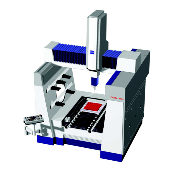
Design of the CMM Design of the CMM A CMM of the series CenterMax is illustrated in the following. 1 Quill cover 2 X-bridge with concertina cover 3 Drive-side and guideway-side 4 Probe head 5 Measuring table 6 Guideway-side 61211-1020202 CenterMax Operating Instructions... -
Page 30: Components And Their Functions
Description of the CMM Components and their functions Bridge The CenterMax is a bridge coordinate measuring machine. The bridge is composed of a crossbeam and two guideways. The quill is guided on the crossbeam of the x-bridge. 1 Crossbeam 2 Drive side and guideway side 3 Quill 4 Guideway. -
Page 31: Coordinate Axes
Measuring volume probed. 1 Measuring volume Coordinate axes Travelling in the x, y and z axes is possible with the coordinate mea- suring machine. The drawing shows the possible travel directions of the bridge. Travel directions 61211-1020202 CenterMax Operating Instructions... -
Page 32: Control
The control for the CenterMax is located in a separate control cabinet. 32 bit / C99 The CenterMax is equipped with a 32 bit control. The control has the designation C99. The housing of the control cabinet has protection class IP54. - Page 33 6 Plate with technical data 7 Attention symbol: Observe the information on the plate! 8 Connector for peripheral devices 9 Power supply of the control cabinet 10 Cables leading to the CMM. 61211-1020202 CenterMax Operating Instructions...
-
Page 34: Operating Elements Of The Control Cabinet
Rotary switch (4) and indicator lamp (5): The rotary switch is used to Drives switch the drives on. Turn the switch clockwise. The switch does not remain in the new position. It returns to its initial position. 61211-1020202 CenterMax Operating Instructions... -
Page 35: Control Console
➤ page 2-8. Control console The CenterMax is equipped with the standard control console on delivery. However, it can also be delivered with the Dynalog control console on request. Each of these control consoles is described in a separate manual. -
Page 36: Operation Of The Joysticks
Right joystick The right joystick is used to move the probe in the x and y direction. x and y direction The bridge moves in the y direction, the quill in the x direction. 2-10 61211-1020202 CenterMax Operating Instructions... - Page 37 (option) Direction Action Left joystick z direction • Push to the rear. The quill moves downwards. • Pull to the front. The quill moves upwards. 2-11 61211-1020202 CenterMax Operating Instructions...
-
Page 38: Calibration Standard
A metal plate is required for mounting the calibration standard on the measuring table. This plate is delivered with the calibration standard. For more information see ➤“Mounting the calibration standard on the measuring table” on page 7-18. 2-12 61211-1020202 CenterMax Operating Instructions... -
Page 39: Options
Components and their functions Options The following special equipment is available for CenterMax: – Loading device – Illuminating device. 2-13 61211-1020202 CenterMax Operating Instructions... -
Page 40: Probe System
Description of the CMM Probe system Probe system types The CenterMax is equipped with the VAST probe system. VAST Application Universal Measuring principle measuring ➤ Further information page 2-15 Components of a probe system The probe system comprises: VAST Probe head ×... -
Page 41: Standard Version Of The Probe System
– If high accuracy is required. – If long, heavy probes are used. In addition to conventional probes, a temperature-sensing probe may Special probes be used. The temperature-sensing probe is used to measure the work- piece temperature. 2-15 61211-1020202 CenterMax Operating Instructions... -
Page 42: Components
Probe weight 600g The adapter plate receptacle may only be loaded with a maximum weight of 600g. Probe length 450mm The length of the probe head including extension must not exceed 450mm. 2-16 61211-1020202 CenterMax Operating Instructions... -
Page 43: Temperature-Sensing Probe
NOTE The VAST probe system is required for the operation of a tempera- ture-sensing probe. For more information see ➤“Notes on temperature measurement” on page 7-9 and ➤“Possibilities” on page 7-10. 2-17 61211-1020202 CenterMax Operating Instructions... - Page 44 Description of the CMM Design A Adapter plate B RST temperature-sensing probe C Temperature sensor 1 Connector 2 Knurled ring with internal thread. 2-18 61211-1020202 CenterMax Operating Instructions...
-
Page 45: Probe
The VAST adapter plate has the following functions; it must ... VAST – hold the probes – fit into the adapter plate receptacle of the probe head – enable probe change via a probe rack. 2-19 61211-1020202 CenterMax Operating Instructions... - Page 46 A probe or stylus consists of a shaft and a probe element or stylus tip. Shaft + probe element Shafts differ with regard to size and material. Furthermore, probe ele- ➤ ments differ with regard to form page 2-21. 2-20 61211-1020202 CenterMax Operating Instructions...
-
Page 47: Probe Elements
The sphere is the standard probe element suitable for most measuring Sphere jobs. Cylinders are preferably used for probing thin sheet-metal parts and Cylinder narrow workpiece edges. Cones are required for two applications: For ... Cone – self-centering probing 2-21 61211-1020202 CenterMax Operating Instructions... -
Page 48: Principles For Assembly
– Clamping technique Preference should be given to the screwing technique. Probes may be assembled individually. Probe kits with different com- ponents are available. Important! The limiting values for probes must be observed when assembling probes. 2-22 61211-1020202 CenterMax Operating Instructions... -
Page 49: Screwing Technique
Extract from the technical data of probes Weight [mm] Hard metal 33,5 23.5 63.5 50.5 114.5 19 92.5 64.5 42.5 65.5 52.5 Ceramic material 2-23 61211-1020202 CenterMax Operating Instructions... -
Page 50: Clamping Technique
A probe rack is recommended for storage if you measure every day with the CMM. When no measurements are carried out with the CMM over a longer period, the probes should be stored in a place protected against environmental influences: 2-24 61211-1020202 CenterMax Operating Instructions... - Page 51 • Wrap the probe in a cloth or lay it on a soft support. This is necessary to protect the adapter plate and probe ele- ments against being scratched. Special probe cabinet The probes are inserted in holders. The probe cabinet is available from ZEISS. 2-25 61211-1020202 CenterMax Operating Instructions...
-
Page 52: Probe Rack
8 holders belong to a probe rack. The holders are preassembled. – Screws and mounting aids. Two probe racks are available for CenterMax. One rack is included in Probe system order numbers the standard version and the other rack can be ordered: Order no. -
Page 53: Chapter 3 Technical Data
Probe system ......... . 5 3- 1 61211-1020202 CenterMax Operating Instructions... -
Page 54: Coordinate Measuring Machine
1200 [mm] Weight [kg] 6000 Workpiece [kg] 1000 Noise level of the CMM [dBA] <70 An additional distance is required for mounting work: min. 200mm. CMM parameters Category Characteristic value Overvoltage category Pollution degree Protection class 61211-1020202 CenterMax Operating Instructions... -
Page 55: Connection Data
20l/min with 5bar Travel speed Creep speed: SLOW function 0 to 5 mm/s Setup mode: MAN operating mode 0 to 70mm/s Series measuring operation: AUTO operating mode Axis max. 300mm/s Vector max. 425mm/s (or 520mm/s) 61211-1020202 CenterMax Operating Instructions... -
Page 56: Environmental Conditions
The following conditions must be fulfilled to guarantee perfect opera- tion of the coordinate measuring machine. Ambient temperature for +5°C to +40°C storage Ambient temperature for 15…35°C operational readiness Ambient temperature for 15…35°C measuring operation Relative humidity 40% to 70% 61211-1020202 CenterMax Operating Instructions... -
Page 57: Probe System
Probe weight, max. 600g / incl. adapter plate Probe length, max. 450mm / stylus + extension Repeatability following probe <1µm / with 200mm probe change length Environmental conditions Ambient temperature for opera- +5°C to +40°C tional readiness 61211-1020202 CenterMax Operating Instructions... - Page 58 Technical data 61211-1020202 CenterMax Operating Instructions...
-
Page 59: Chapter 4 Transport And Installation
Installation ..........4 4- 1 61211-1020202 CenterMax Operating Instructions... -
Page 60: Transport
The packing material or the transport containers must not be dam- aged. The packing material may only be removed at the installation site by a ZEISS service engineer. The transport pallets and shipping containers must be stored in a cov- Ambient temperature +5°C to +40°C... - Page 61 Transport – Dimensions: Are the height and width of the doorways and routes sufficient for the transport containers and the fork-lift truck? – Fork-lift truck: Does the fork-lift truck comply with the ➤ requirements? page 4-2. 61211-1020202 CenterMax Operating Instructions...
-
Page 62: Installation
ZEISS for planning purposes. An additional foundation may be necessary. ZEISS can carry out a vibration analysis for you. You can order it under the order no. 600008-0276. • Dial +49.(0)7364.20.3471 if you want ZEISS to carry out a vibra- tion analysis. -
Page 63: Prerequisites For Installation
Installation Prerequisites for installation The following preparations must be made prior to installation of the CMM by ZEISS service engineers: – Provision of steel plates – Installation of power supply – Installation of compressed-air supply – Adaptation of CMM to room temperature You will find the data required for preparation in the document "Installation Instructions“. - Page 64 Transport and installation 61211-1020202 CenterMax Operating Instructions...
- Page 65 Visual check......... . 14 Start-up preparation checklist ......15 5- 1 61211-1020202 CenterMax Operating Instructions...
-
Page 66: Before You Start
Preparations for start-up Before you start! Initial start-up is carried out by a ZEISS service engineer. However, you Initial start-up by a ser- vice engineer must familiarize yourself with the preparations required for start-up and know as well as observe the corresponding safety instructions. -
Page 67: Connections
Connection of the power supply is part of the CMM installation pro- By ZEISS service engi- neers cedure. It may be carried out only by ZEISS service engineers. The CMM power supply is provided by the control cabinet. A permanent connection must be provided for the control cabinet power supply. -
Page 68: Requirements For Compressed-Air Supply
➤ page 5-5 3 Compressed-air supply at the installation site. The connection for the dampers of the CenterMax is located behind the left door. The connections for the axes and the special equipment are located behind the middle door. 61211-1020202... -
Page 69: Pressure Gages
Option: e.g. loading device 5bar Air bearings in the CMM 5bar The values set by the ZEISS service engineer may slightly deviate from the indicated values. Important! The valves of pressure gages which are not connected must be closed. The connection shank should be covered by a cap. -
Page 70: Adjusting The Pressure
If the required pressure is not indicated, proceed as follows: • Identify the cause of the decrease or increase of pressure ➤“Faults during the measuring run” on page 8-3. • Call a ZEISS service engineer if you cannot find or eliminate the cause. Filter units Several filter combinations are offered for the CMM. - Page 71 Connections Combination 2 Combination 1 + Optional membrane dryer for filtering out moisture 3 Combination 2 + Optional combination 1 61211-1020202 CenterMax Operating Instructions...
-
Page 72: Mounting The Probe Rack (Option)
Preparations for start-up Mounting the probe rack (option) The probe rack is mounted by ZEISS service engineers during the ini- tial start-up. If the probe rack is to be installed in another location or a second probe rack is to be installed, you have to observe certain points. - Page 73 1 Holder (storage position) 2 Profile rail 3 Guideway for holder – at the top or at the bottom. The holders are fastened to the profile rail using Allen screws. Two screws are required for VAST holders. 61211-1020202 CenterMax Operating Instructions...
- Page 74 • Proceed in the same way for sliding further holders on the profile rail. The permissible number depends on the probe system and the pro- file rail length. • Reattach the cap to the profile rail. 5-10 61211-1020202 CenterMax Operating Instructions...
- Page 75 Mounting the probe rack (option) • Distribute the holders evenly on the profile rail and tighten the screws (2). 5-11 61211-1020202 CenterMax Operating Instructions...
- Page 76 Preparations for start-up Installing a probe rack In the case of the CenterMax, two different positions on the guide- way side can be used for installing the profile rail. If you only have one profile rail, you must mount it at the lower position first. This is neces- sary for reasons of safety.
- Page 77 NOTE If you require more holders than can be mounted on two profile rails, it is possible to mount a third profile rail on the drive side. However, this will decrease the effective measuring range. 5-13 61211-1020202 CenterMax Operating Instructions...
-
Page 78: Visual Check
– the line is connected correctly to the supply line and the CMM. Cables The cables from the control cabinet to the CMM are installed in a Cable duct cable duct. • Make sure that the cable duct is not damaged. 5-14 61211-1020202 CenterMax Operating Instructions... -
Page 79: Start-Up Preparation Checklist
– Does the compressed-air supply have sufficient pressure? – Is the required pressure indicated? Probe rack (optional) – Have all requirements regarding the probe rack been met? – Has the probe rack been installed correctly? – Is probe change possible without collision? 5-15 61211-1020202 CenterMax Operating Instructions... - Page 80 Preparations for start-up 5-16 61211-1020202 CenterMax Operating Instructions...
- Page 81 Start-up checklist ........19 6- 1 61211-1020202 CenterMax Operating Instructions...
-
Page 82: Clamping The Workpiece On The Measuring Table
Furthermore, the surface of the measuring table and the workpiece may be damaged. • Clean the measuring table before placing a workpiece on the mea- suring table. 61211-1020202 CenterMax Operating Instructions... -
Page 83: Clamping The Workpiece
Chucks are generally made of metallic materials. Chucks made of Metal, plastic, wood plastic or wood may also be used if necessary. Workpiece positioning Position the workpiece so that all required measurements can be car- ried out without changing the workpiece position. 61211-1020202 CenterMax Operating Instructions... -
Page 84: Lowering The Workpiece Onto The Measuring Table
• Then replace the elastic elements with rigid supports. NOTE Metal blocks clamped by clamping devices can be used as rigid sup- ports. Screw fasteners can be used alternatively. These fasteners can be screwed into the threaded holes in the measuring table. 61211-1020202 CenterMax Operating Instructions... -
Page 85: Switching The Cmm On
1 Connect power supply; switch power supply on by means of the main switch 2 Switch the control on. 3 Switch the drives on. 4 Select the operating mode 5 Switch the computer on and start the measuring software. 61211-1020202 CenterMax Operating Instructions... - Page 86 This is necessary since the internal computer requires a certain amount of time for booting. The booting process must be termi- nated before the drives are switched on. The LEDs on the control panel flash during the booting process. 61211-1020202 CenterMax Operating Instructions...
- Page 87 Switching the computer on • Switch the computer on and other peripheral devices, e.g. the printer. • Boot the computer; start the operating system. • Start the measuring software. 61211-1020202 CenterMax Operating Instructions...
-
Page 88: Checking The Protective Circuit
• Check the protective circuit on a monthly basis. Check When performing the check, you must proceed as follows: x axis • Move the crossbeam forward just far enough so that you can grasp the quill housing with one hand. 61211-1020202 CenterMax Operating Instructions... - Page 89 Check by a ZEISS service engineer stop probe movement. If the movement can not be stopped in this way, the protective circuit must be checked immediately by a ZEISS service engineer. • Call your service engineer and arrange for him to check the protec- tive circuit.
- Page 90 You may press against the crossbeam only on the drive side. • Do not press against the probe head and quill or against the cross- beam on the guideway side. The probe head, quill and crossbeam could be damaged. 6-10 61211-1020202 CenterMax Operating Instructions...
-
Page 91: Mounting / Changing The Probe Head
Mounting / changing the probe head Mounting / changing the probe head Important! With the CenterMax, the probe head must not be changed by the operator. The probe head may be changed only by a ZEISS service engineer. 6-11 61211-1020202... -
Page 92: Probe Assembly
• Use the pin included in the probe kit to tighten the components. Important! Observe the limiting values regarding weight and length when assem- bling the probe. The limiting values depend on the probe system. • Observe the limiting values ➤“Limiting values” on page 6-14. 6-12 61211-1020202 CenterMax Operating Instructions... -
Page 93: Criteria And Limiting Values For Assembling Probes
It is preferable to use components shaped according to your corre- sponding requirements. You can also make such components your- self, provided that you observe the permissible limiting values. • Use only components that are in perfect condition. Requirements for probe components: 6-13 61211-1020202 CenterMax Operating Instructions... -
Page 94: Example
Probe length – including 450mm extension: Example Connecting parts are usually required to assemble the required probe configuration. It is also possible to screw the probe directly into the ➤ adapter plate page 6-15. 6-14 61211-1020202 CenterMax Operating Instructions... - Page 95 Probe assembly Example of probe assembly via the screwing technique using the Screwing technique VAST adapter plate: A Probe stylus in adapter plate B Extension in adapter plate 6-15 61211-1020202 CenterMax Operating Instructions...
-
Page 96: Inserting / Removing The Probe
1 Initiate the procedure by means of the measuring software. Then, insert the probe within 20 seconds. If the probe is not inserted within this time, you have to repeat this procedure. 6-16 61211-1020202 CenterMax Operating Instructions... -
Page 97: Removing The Probe (Manually)
Set the delay so that enough time always remains to grasp the probe after initiating probe removal. This is essential to prevent damage to probes, workpieces, or the measuring table caused by falling probes. 2 Remove the probe. 6-17 61211-1020202 CenterMax Operating Instructions... - Page 98 Start-up VAST: Hold the probe; it falls off automatically. Special features of probe systems Automatic probe change Information on automatic probe change is provided in the chapter ➤“Automatic probe change” on page 7-30. 6-18 61211-1020202 CenterMax Operating Instructions...
-
Page 99: Start-Up Checklist
– Has the protective circuit been checked? page 6-8. Probe assembly ➤ – Have the criteria for probe assembly been observed? page 6-13. – Have the limiting values for the probe been observed? ➤ page 6-14. 6-19 61211-1020202 CenterMax Operating Instructions... - Page 100 Start-up 6-20 61211-1020202 CenterMax Operating Instructions...
- Page 101 Terminating a measuring run ......33 7- 1 61211-1020202 CenterMax Operating Instructions...
-
Page 102: What You Should Know
1 Probe 2 Rectangular block (=workpiece) 3 Possible probing directions 4 Measuring table 61211-1020202 CenterMax Operating Instructions... -
Page 103: Types Of Measurement
Single point probing makes it possible to measure a workpiece com- Complete measurement pletely. All dimensions of the workpiece are calculated by means of the probed single points. No information can be obtained regarding form. For this, scanning and a special software are required. 61211-1020202 CenterMax Operating Instructions... -
Page 104: Multipoint Measurement
A Lowering the probe and probing the workpiece; with the left joystick. B - D Move the probe over the workpiece with the right joystick. The position in the z direction remains unchanged. D Lifting the probe. 61211-1020202 CenterMax Operating Instructions... -
Page 105: Scanning
– VAST stage 3: exact acquisition of dimensions and position. Scanning with maximum precision for measuring dimensions and position. – VAST stage 4: rapid acquisition of the position. Scanning with maximum dynamics for measuring the position. 61211-1020202 CenterMax Operating Instructions... -
Page 106: Collision Protection
If the quill or the probe head collides with an obstacle, the guideway and other components of the CMM may be damaged. In this case, perfect measuring operation cannot guaranteed. • If measurements are not possible after a collision, call a ZEISS ser- vice engineer or our hotline. NOTE After a collision, the probe must be recalibrated and the workpiece position (w position) must be determined again. -
Page 107: All Axes Unclamped
You can cause the measuring force to act in a certain axis by clamping specified axes. Two axes are clamped when probing single points. The probe can be moved in the axis of the probing direction. 61211-1020202 CenterMax Operating Instructions... -
Page 108: Self-Centering Probing
Bottom of narrow V grooves. One axis clamped 1 Probing in z direction; movable axis. 2 y axis is clamped; no movement possible in y axis. 3 Self-centering in x axis – to the bottom of the groove. 61211-1020202 CenterMax Operating Instructions... -
Page 109: Temperature-Sensing Probe
– The workpiece should be probed in the axis direction of the tem- perature-sensing probe. The max. angle between the axis direction and the normals of the workpiece surface must no exceed ±5°. Perfect measuring opera- tion cannot be guaranteed with larger angles. 61211-1020202 CenterMax Operating Instructions... -
Page 110: Possibilities
4 Maximum deflection of temperature sensor: ±5°. Possibilities A temperature sensing probe offers the following possibilities: – Temperature compensation. – Inclusion of the temperature-sensing probe in a CNC program. – Temperature monitoring. – Temperature check. – Temperature recording. 7-10 61211-1020202 CenterMax Operating Instructions... -
Page 111: Operating Mode
The CMM allows measuring in two operating modes: manual and automatic. In the manual mode the workpiece is probed by means of the joy- MAN operating mode ➤ sticks. The joysticks are located on the control console operating instructions for the control console. 7-11 61211-1020202 CenterMax Operating Instructions... -
Page 112: Measuring Software
Furthermore, measuring software options are available for special measuring tasks, e.g. KUM, SAM, GON. Calypso is the standard measuring software for the Windows NT Windows NT operating system. Provacs and Holos, for example, are used for special measuring tasks. 7-12 61211-1020202 CenterMax Operating Instructions... -
Page 113: Safety Instructions
For calibration, the same measuring force and clamping of the axes must be set as later for workpiece measurement. • Perform the calibration in the same way as you intend to probe the workpiece later on, i.e. with the same measuring force and axis clamping. 7-13 61211-1020202 CenterMax Operating Instructions... -
Page 114: Preparations For A Measuring Run
The reference point or origin is located in the upper right-hand corner of the measuring volume. It must be determined by a reference point travel prior to the measuring run ➤“Carrying out a reference point travel” on page 7-16. 7-14 61211-1020202 CenterMax Operating Instructions... - Page 115 Preparations for a measuring run Signs of the coordinates: +x, -y and -z. Signs of the coordi- nates 1 Reference point 2 Measuring volume 3 Safety position 4 Zero point 5 Coordinate system 7-15 61211-1020202 CenterMax Operating Instructions...
-
Page 116: Carrying Out A Reference Point Travel
Probe calibration NOTE The measuring software is required for the following procedure. • Please read the corresponding chapters in the operating instruc- tions for the measuring software. 7-16 61211-1020202 CenterMax Operating Instructions... -
Page 117: What You Should Know
Preparation What is required for calibration? The following is required for calibration: – Calibration standard A calibration standard with a highly accurate ceramic sphere is usually used ➤“Calibration standard” on page 2-12. 7-17 61211-1020202 CenterMax Operating Instructions... - Page 118 1 Rotary lever for activating the magnet 2 Metal plate with through holes 3 M12 threaded hole in the measuring table 4 Example of position of metal plate (for mounting calibration standard). 7-18 61211-1020202 CenterMax Operating Instructions...
-
Page 119: Calibration Procedure
NOTE Semi-automatic calibration should be carried out for all probe sys- tems. Tensor calibration should be carried out for the VAST measuring probe system. This is important since the measuring force causes a 7-19 61211-1020202 CenterMax Operating Instructions... - Page 120 If the result is not satisfactory, repeat the calibration or look for plausible causes. It might be necessary to decide whether or not to accept measuring inaccuracies. 8 Repeat points 2 to 6 for all other styli of the probe. 7-20 61211-1020202 CenterMax Operating Instructions...
-
Page 121: Causes Of Large Deviations
The temperature of the probe material as well as the material properties change as a result of hand heat. Even minor differences in temperature influence the material prop- erties. The degree of this effect depends on the probe compo- nents. 7-21 61211-1020202 CenterMax Operating Instructions... -
Page 122: Temperature Compensation
Two temperature sensors are included in the standard equipment of the CMM. These sensors are required for temperature compensation. The temperature sensors consist of a copper block, a long cable and a Sensor components connector. 1 Copper block 2 Connector 7-22 61211-1020202 CenterMax Operating Instructions... - Page 123 Temperature compensation can be carried out continuously. In some cases it is imperative to carry out temperature compensation: – Carry out temperature compensation each time you measure a new workpiece. Temperature compensation values can be integrated in the CNC workpiece measurement program. 7-23 61211-1020202 CenterMax Operating Instructions...
-
Page 124: Probing The Workpiece
4 Probe the workpiece. Probing conditions For probing, certain conditions must be fulfilled. The conditions depend on the probe system. The following conditions must be ful- filled: – Constant probing speed. 7-24 61211-1020202 CenterMax Operating Instructions... -
Page 125: Probing Speed
• If the speed is too high for certain probings, reduce the maxi- mum possible speed. Turn the control knob counterclockwise to reduce the speed. NOTE When probing oblique workpiece surfaces with an angle between 30° and 50°, the probing speed has to be reduced. 7-25 61211-1020202 CenterMax Operating Instructions... -
Page 126: Aligning The Probe
/ no errors – Are the probing surfaces of the workpiece clean? – Is the workpiece secured against shifting? – Are the probe assembly criteria fulfilled? – Are the probe and the stylus in perfect condition? 7-26 61211-1020202 CenterMax Operating Instructions... -
Page 127: Special Features Of Vast Probe System
The extent of these form changes influences the precision of set? the calculated values. In order to avoid falsified measuring data, the measuring force should be adapted to the characteristics of the work- piece material. 7-27 61211-1020202 CenterMax Operating Instructions... -
Page 128: Precision Positioning During Probing
Precision positioning during probing With the VAST probe system, the joysticks are temporarily deactivated immediately after the probe contacts the workpiece. The CMM con- trol takes over the precision positioning of the probe. The measured value is accepted. 7-28 61211-1020202 CenterMax Operating Instructions... -
Page 129: Notes On Scanning
• Check the condition of the probe elements and clean them. For information on how to remove aluminum deposits, please refer ➤ page 9-6. • If the probe element is damaged, replace the stylus. 7-29 61211-1020202 CenterMax Operating Instructions... -
Page 130: Automatic Probe Change
NOTE The measuring software is required in order to carry out this proce- dure. • Please read the corresponding chapters in the operating instruc- tions for the measuring software. 7-30 61211-1020202 CenterMax Operating Instructions... -
Page 131: Tips For Effective Operation
CMM switched on. The CMM should not be switched off in the following cases: – If it is operated during multiple shifts. – If workpiece measurement takes several days and the CMM should measure under constant conditions. 7-31 61211-1020202 CenterMax Operating Instructions... -
Page 132: Evaluating The Measuring Data
Magnetic field – A fault was caused by a magnetic field. Possible causes of a magnetic field: e.g. workpiece, clamping tool, probe extensions. Probing – Probing was not carried out perpendicular to the probing surface. 7-32 61211-1020202 CenterMax Operating Instructions... -
Page 133: Terminating A Measuring Run
• Press the quickstop button on the control cabinet and unlock it again. 6 Switch off the control. • Set the rotary switch to the "OFF" position. 7 Switch off the power supply. • Turn the main switch counterclockwise to the "0" position. 7-33 61211-1020202 CenterMax Operating Instructions... - Page 134 Measuring operation 7-34 61211-1020202 CenterMax Operating Instructions...
- Page 135 If nothing else helps, ... – hotline! ......9 8- 1 61211-1020202 CenterMax Operating Instructions...
-
Page 136: Errors Occurring Prior To The Measuring Run
• If the above mentioned errors can be excluded, put the CMM out of operation and repeat the start-up procedure. • If it is then still not possible to carry out a measuring run, call a ➤ ZEISS service engineer or our hotline page 8-9. 61211-1020202 CenterMax Operating Instructions... -
Page 137: Faults During The Measuring Run
Filter clogged. • Change the filter. Air noise at the air Pressure too high. • Reduce the pressure in the sup- Indicating instru- bearings. ments ply line. • Call a ZEISS service engineer. 61211-1020202 CenterMax Operating Instructions... - Page 138 • Reallocate storage position. probe rack or stor- age position was changed. Collision: • Reallocate storage position and missing intermedi- set intermediate positions. ate positions. Two probes allo- • Reallocate storage position. cated to one stor- age position. 61211-1020202 CenterMax Operating Instructions...
-
Page 139: Special Measures
The drives can only be switched on again after the probe head has been positioned inside the measuring volume. Returning the probe head to the measuring volume To return the probe head to the measuring volume, proceed as fol- lows: 61211-1020202 CenterMax Operating Instructions... - Page 140 • Do not push against the quill or the probe head. The probe head and quill may be damaged. y direction: To return the probe head to the measuring volume, push against the housing of the column on the drive side of the bridge. 61211-1020202 CenterMax Operating Instructions...
- Page 141 Move the crossbeam forward far enough so that you can grasp the cover with your hand. The right-hand side of the cover (1) is provided with an opening. You can access the switch for deactivating the fall brake through this opening. 61211-1020202 CenterMax Operating Instructions...
- Page 142 As soon as the indicator lamp above the switch lights up, the drives are switched on. The rotary switch does not engage. It snaps back as soon as it is released. 61211-1020202 CenterMax Operating Instructions...
-
Page 143: If Nothing Else Helps
If a fault cannot be eliminated and occurs again after a renewed start- Hotline: +49 (0)180 3336337 up, call a ZEISS service engineer or our hotline in Oberkochen (Ger- many). The phone number of our hotline is: +49 (0)180 3336337. 61211-1020202... - Page 144 Errors and faults 8-10 61211-1020202 CenterMax Operating Instructions...
-
Page 145: Chapter 9 Maintenance And Care
Care ..........4 9- 1 61211-1020202 CenterMax Operating Instructions... -
Page 146: Maintenance
We recommend concluding a maintenance agreement to guarantee Maintenance agree- ments safe operation. ZEISS offers maintenance agreements which relieve you of any need to worry about maintenance. • If you would like to subsequently conclude a maintenance agree- ment retrospectively, call our hotline. - Page 147 Measuring system For example functioning, precision Control For example operator’s controls on the control cabinet; control panel NOTE When concluding a maintenance agreement, you also must specify any optional equipment to be covered. 61211-1020202 CenterMax Operating Instructions...
-
Page 148: Care
Preventive care also includes making sure that all workpieces to be measured are clean. The workpieces must be free from machining res- idues (e.g. metal chips, oil) and dust. • Clean the workpieces before placing them on the measuring table. 61211-1020202 CenterMax Operating Instructions... -
Page 149: Overview
Measuring table The workpieces must have full contact with the measuring table. Any hard particle below the workpiece may lead to inaccurate measure- ments. Furthermore, the surface of the measuring table and the workpiece may be damaged. 61211-1020202 CenterMax Operating Instructions... - Page 150 For cleaning, proceed as follows: • Wear rubber gloves and safety glasses. • Immerse a cloth (e.g. cotton cloth) into one of the two solvents and clean the probe element with the cloth. 61211-1020202 CenterMax Operating Instructions...
- Page 151 The adapter plate and the adapter plate receptacle must be protected against soiling. • Put a protective cap on the adapter plate receptacle of the probe head whenever no probe is inserted in the adapter plate receptacle or the probe head is not in use. 61211-1020202 CenterMax Operating Instructions...
-
Page 152: Inspection Measures
Intensive care of the CMM also includes inspection of the compo- nents used. Regular inspection of the probes is required to ensure correct work- piece measurement. • Check the styli, other probe components and the adapter plate regularly. 61211-1020202 CenterMax Operating Instructions... -
Page 153: Cleaning/Changing The Filter Mat
The filter mat in the intake hole must be cleaned every three months. 1 Fan 2 Air filter 3 Warning label: "Verschmutztes Luftfilter austauschen oder reinigen. / Clean or replace soiled air filter.“ 61211-1020202 CenterMax Operating Instructions... -
Page 154: Changing The Compressed Air Filters
The glass windows make it possi- ble to check the degree of soiling. Danger! Switch off the compressed air before changing the filters. A Fine filter B Extra fine filter 9-10 61211-1020202 CenterMax Operating Instructions... - Page 155 The filter element for the fine filter consists of a sleeve pulled over a guide. • To change filters,, remove the sleeve from the guide and put on a new one. • Screw the guide back in. • Reattach the filter cap. 9-11 61211-1020202 CenterMax Operating Instructions...
- Page 156 Maintenance and care 9-12 61211-1020202 CenterMax Operating Instructions...
- Page 157 Index identification 2-2 improper use 1-7 Adapter plate initializing 7-6 function 2-14 installation 4-4 VAST 2-19 number of the CMM type 2-2 Axis clamping 7-6 serial number 2-2 clamped status 7-7 series 2-2 unclamped 7-7 switch off 7-33 switch-on 6-5 switch-on sequence 6-5 Bridge 2-4 transport 4-2...
- Page 158 Drive side 2-4 purpose 9-2 Drives Measuring data automatic cutoff 6-8 causes of deviations 7-32 switch off 2-9, 2-10 deviations 7-32 switch on 2-8 evaluate 7-32 switching on 6-7 Measuring force 7-8, 7-27 Drive-side column 2-3 standard value 7-28 Measuring range 3-2 Measuring run start-up 6-5 EMERGENCY STOP button 2-10...
- Page 159 configuration 2-19 Protective circuit 6-8 conical probe 7-9 check in the y axis 6-10 example for screwing technique 6-15 check of x axis 6-8 insertion 6-16 function of protective circuit 6-8 joining elements 2-20 Push-and-turn switch 2-8 limiting values for probe construction 6-14 probe elements 2-21 Quill 2-3, 2-4, 2-6...
- Page 160 Stylus 2-20 measuring force 7-27 Switch precision positioning 7-28 key-operated switch 2-8 special features 7-27 main switch 2-8 Vibration analysis 4-4 Push-and-turn switch 2-8 rotary switch for drives 2-8 Rotary switch for the control 2-8 Warranty 1-5, 1-6 Weight workpiece, maximum 3-2 Technical data Windows-NT measuring software 7-12 CMM 3-2...
- Page 161 Glossar Term Explanation Adapter plate Component of the probe; inserted in the adapter plate receptacle. Adapter plate receptacle Component of the probe head; used for holding the adapter plate ATAC Adaptive Touch Advanced Control Bridge The bridge consists of two supports and the crossbeam. Calibration standard Calibration tool;...
- Page 162 Glossary 61211-1020202 Operating Instructions...
- Page 163 Appendix Application examples Components Probe systems in operation Calibration: RDS/RST probe system: VAST: probe system Circle scanning: Probing a part feature: "circle“: 61211-1020202 Operating Instructions Appendix...
- Page 164 Appendix 61211-1020202 Operating Instructions...
- Page 166 61211-1020202 Operating Instructions 01/02...
Need help?
Do you have a question about the CenterMax and is the answer not in the manual?
Questions and answers