
Summary of Contents for AC&T System ETOS-XP Series
- Page 1 Industrial Network Server ETOS- XP Series ETOS-XP SERIES USER’S GUIDE AC&T System Co., Ltd. 2017-06 Revision 1.1...
- Page 2 !!! PRECAUTIONS!!! (Please read it before using) When using the ETOS-XP series, please read this manual and the relevant manuals introduced in this manual, and handle devices correctly paying attention to safety. The precautions described in this manual are only for the ETOS-XP series.
- Page 3 Wiring must be done 100 mm or more away from them. When controlling the ETOS-XP series that is connected to a peripheral device, make sure that the whole system operates safely at all times. In addition, be sure to read the manual carefully and check safety before operating the ETOS-XP series.
- Page 4 [Precautions while Operating] Precautions When controlling the ETOS-XP series in operation, read this user's manual thoroughly and check the safety. Incorrect parameter setting or program change may cause breakdown of the system, damage to the machine or accident.
- Page 5 ETOS-XP Series User Manual Some or all of this manual cannot be used by illegal reproduction. The contents of this manual may be changed without prior notice to improve the function of the product. Revision History Revision No. Date Change...
- Page 6 CHAPTER OVERVIEW This chapter introduces the functional features of ETOS-XP. CONTENTS Product Overview Main Features Products list - 6 -...
- Page 7 In addition, the ETOS-XP series provides protocol editing functions as well as flexible programming languages for the sake of exchanging data between heterogeneous protocols The ETOS-XP series provides users with the functions of parameter setting, frame and process editing. It enables the users to build various integrated communication systems required by the users.
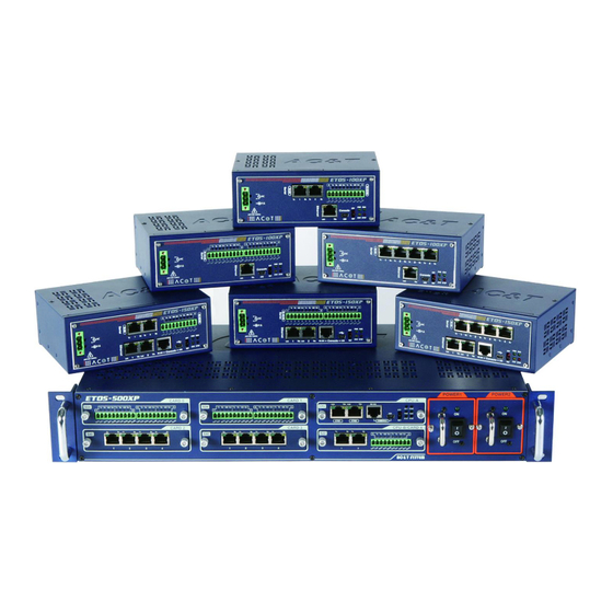
- Page 8 1.3. Products List The ETOS-XP series consists of 100XP / 150XP / 500XP, and each product has various models as shown in the following table according to the communication functions that it supports. The number of RS-232 ports and RS-422 / RS-485 ports of ETOS-XP series can be freely configured within the maximum number of supported ports.
- Page 9 Single: 20 Serial(RS-232,RS-422/RS-485) Redundancy: 16 I/O CARD 1.3.2. How to Assign Model Names Model name of ETOS-XP series shall be assigned as follows. ETOS-XP series: Name of Series Type ETOS-RD: Windows Software for configuration and programming ETOS-XP. ETOS-[A] XP-[B][C][D]...
- Page 10 1.3.3. H/W Specifications Compare the major H/W specifications by ETOS-XP item [ ETOS-XP ] Item ETOS-100XP ETOS-150XP ETOS-500XP 32Bit RISC 60MHz 32Bit RISC 600MHz 32Bit RISC 1000MHz System Memory 32MBytes 512MBytes 512MBytes Program Memory 1 Mbytes 4 Mbytes 4 Mbytes User Memory 512Kbytes 16Mbytes+512Kbytes...
-
Page 11: Product Specification
PRODUCT SPECIFICATION CHAPTER This chapter describes general function specifications. Contents General Specification Power supply Specification Battery Specification Cable Specification Communication Specification LED Display Contents - 11 -... - Page 12 The following are the general performance specifications for product, and specifications for power supply and cable. 2.1. General Specification The following are the explanations for the operating environment, electricity and mechanical specifications of ETOS-XP Series. Related Item Specification Specification Operating -10℃∼+60℃...
- Page 13 Power supply Specifications 2.2. The following is the specifications for rated input voltage and power supply capacity for each product. Current Power Product Input Power Supply Consumption Consumption ETOS-100XP 300mA or less 64VA AC 100V ~ 240V Free Voltage ETOS-150XP 300mA or less 64VA (50/60Hz)
- Page 14 damaged or leakage current occurs due to the circuit abnormality such as leakage current, the warning message may occur earlier. 2.3.4. Battery Voltage Monitoring To know the battery voltage drop in advance, the internal system flags SysBatteryLow and SysBatteryVolt are periodically monitored. Please connect to external alarm device and check at all times (Please refer to "ETOS-RD User Guide"...
- Page 15 To remove the external battery, please refer to the pictures below. (Example of ETOS-500XP) ① Unscrew battery cover to open the ② Remove the mounting cover from the mounting cover. holder. ④ Open the battery compartment of the ③ Disconnect the connector. mounting cover and remove the battery from the mounting cover.
- Page 16 2.4. Cable Specification This section is the standard for the cables used for communication in ETOS-XP. If you do not use the recommended cable (especially in long distance communication), be careful because communication may become unstable or communication may be impossible. 2.4.1.
- Page 17 2.4.2. Ethernet Cable Ethernet provided by ETOS-XP series must be 10/100/1000 Base-T (X). The Ethernet cable must be Category 5 class or more cables using the RJ45 connector and meet the IEEE802.3 standard. ※ Example of Cable Use Item Name : UTP Cable Type Name : Enhanced CAT.5 4P...
- Page 18 2.4.3. Optical Cable This is used for communication through optical cable. The following table lists the recommended cable specifications. When using cables other than those recommended, use the cables that meet the specifications in the table. Optical cable must use Multi-Mode or Single Mode cable. ...
- Page 19 2.5. Communication Method Standard 2.5.1. Ethernet [10/100/1000 Base-T(X)] Item Specification ETOS-100XP: 10Mbps /100Mbps Speed ETOS-150XP: 10Mbps /100Mbps /1Gbps ETOS-500XP: 10Mbps /100Mbps /1Gbps Transmission Method Baseband Specifi- cation Maximum Distance 100m(Node-Hub) Protocol TCP/IP, UDP/IP, ARP, DHCP, ICMP Communication Access Method CSMA/CD 2.5.2.
- Page 20 2.6. LED Display Contents ETOS-XP displays the system status information and communication status through LED. 2.6.1. ETOS-100XP 2.6.1.1. ETOS-100XP LED [ETOS-100XP Front LED Panel] LED Status Name LED Color Operating Status GREEN Power LED : ON when power is ON GREEN Mode LED : Blink during SW Run / Remote run STAT...
- Page 21 2.6.3. ETOS-500XP 2.6.3.1. ETOS-500XP LED (CPU) [Front LED Panel of ETOS-500XP ] LED Status Description Name Color Operating Status GREEN Active CPU ON, Standby CPU Off among redundant CPU SYNC YELLOW ON at the synchronization mode of among redundant CPU GREEN ON when power is ON GREEN...
- Page 22 2.6.4.2. SIO RS-232 2Port + RS-422/RS-485 2Port LED [Front LED of RS-232 2Port + RS-422/RS-485 2Port] LED Status during Normal Operation Name LED Color Operating Status GREEN ON at TX of Serial CH1 YELLOW ON at RX of Serial CH1 GREEN ON at TX of Serial CH2 YELLOW...
- Page 23 2.6.4.3. RS-422/RS-485 4Port LED [Front LED of RS-422/RS-485 4Port] LED Status Name LED Color Operating Status GREEN Serial CH1 의 TX 시 ON GREEN Serial CH1 의 RX 시 ON YELLOW ON at RS-422 mode ON at frame error GREEN ON at TX of Serial CH2 GREEN...
-
Page 24: Installation And Wiring
CHAPTER INSTALLATION AND WIRING This chapter explains specifications required for installation and wiring of ETOS-XP Series. Contents Power Supply and Connector(ETOS-100XP/150XP) Power Supply and Connector(ETOS-500XP) Ethernet connection Serial connection - 24 -... - Page 25 INSTALLATION AND WIRING This chapter explains specifications of power supply and connector pins required for the installation and wiring of ETOS-XP Series. 3.1. Power Supply and Connector of ETOS-100XP/150XP This section describes the specifications of power supply and connector of ETOS-100XP / 150XP.
- Page 26 3.3. Ethernet Connection 3.3.1. How to Connect the Ethernet Port The ETOS-XP series offers up to four Ethernet ports. The RJ-45 connector must be used for the connection and the pin array is as follows. Name Signal Direction Function Description ...
- Page 27 They are located on the front side of the product as shown below. 3.4.1. RS-232 port Specifications and Wiring The following table shows each pin name, function, and data direction of the RS-232 serial port of the ETOS-XP series. [Serial Port Specification for RS-232 of ETOS-XP Series] Name Signal Direction Function Description ...
- Page 28 Connection diagram of RS-232C Null modem connection refers to the method that directly connects RS-232 port of ETOS-XP series to external device. External device and RS-232 port of ETOS-XP series must be connected as in the following picture. ETOS (RJ-45) 외부통신기기...
- Page 29 3.4.2. RS-422 port Specifications and Wiring The following table shows each pin name, function, and data direction of the terminal block (10p) for RS-422/RS-485 serial port of the ETOS-XP. [Specification of RS-422 port] Pin No. Name Signal Direction Function Description ...
- Page 30 3.4.3. RS-485 port Specifications and Wiring The following table shows the pin names, functions, and data direction of the RS-485 communication port. [RS-485 Port Specification of ETOS-XP Series] Pin No. Name Signal Direction Function Description 1-3, 6-8 TRX+ ↔ RS-485 Transmit/Receive Data(+)
- Page 31 Appendix - Dimension A.1. ETOS-100XP/150XP [Unit: mm] - 31 -...
- Page 32 A.2. ETOS-500XP [Unit: mm] - 32 -...
Need help?
Do you have a question about the ETOS-XP Series and is the answer not in the manual?
Questions and answers