Table of Contents
Advertisement
CURTIS INSTRUMENTS, INC.
200 Kisco Avenue
Mount Kisco, NY 10509 USA
Tel: 914-666-2971
Fax: 914-666-2188
www.curtisinst.com
MANUAL
1 2 4 3
Generation 2
MultiMode™
MOTOR CONTROLLER
© 2002 CURTIS INSTRUMENTS, INC.
DESIGN OF CURTIS PMC 1200 SERIES
CONTROLLERS PROTECTED BY U.S.
PATENT NO. 4626750.
1243
2 Manual, p/n 37044
GEN
Rev. A: October 2002
Advertisement
Table of Contents
Troubleshooting

Related Manuals for Curtis Instruments MultiMode 1243 Generation 2


Summary of Contents for Curtis Instruments MultiMode 1243 Generation 2
- Page 1 MANUAL 1 2 4 3 Generation 2 MultiMode™ MOTOR CONTROLLER © 2002 CURTIS INSTRUMENTS, INC. DESIGN OF CURTIS PMC 1200 SERIES CONTROLLERS PROTECTED BY U.S. PATENT NO. 4626750. CURTIS INSTRUMENTS, INC. 200 Kisco Avenue 1243 2 Manual, p/n 37044 Mount Kisco, NY 10509 USA Rev.
-
Page 2: Table Of Contents
CONTENTS 1 2 3 4 5 6 7 8 9 0 1 1 2 3 4 5 6 7 8 9 0 1 CONTENTS 1 2 3 4 5 6 7 8 9 0 1 1 2 3 4 5 6 7 8 9 0 1 1 2 3 4 5 6 7 8 9 0 1 1 2 3 4 5 6 7 8 9 0 1 1 2 3 4 5 6 7 8 9 0 1... - Page 3 CONTENTS 1 2 3 4 5 6 7 8 9 0 1 1 2 3 4 5 6 7 8 9 0 1 Min. Forward Regen ..........27 1 2 3 4 5 6 7 8 9 0 1 1 2 3 4 5 6 7 8 9 0 1 1 2 3 4 5 6 7 8 9 0 1 1 2 3 4 5 6 7 8 9 0 1 Min.
- Page 4 CONTENTS 1 2 3 4 5 6 7 8 9 0 1 1 2 3 4 5 6 7 8 9 0 1 Hourmeter Parameters ............45 1 2 3 4 5 6 7 8 9 0 1 1 2 3 4 5 6 7 8 9 0 1 1 2 3 4 5 6 7 8 9 0 1 1 2 3 4 5 6 7 8 9 0 1 Adjust Hours High ............
- Page 5 CONTENTS 1 2 3 4 5 6 7 8 9 0 1 2 3 4 5 6 7 8 9 0 6. PROGRAMMER MENUS ............ 65 1 2 3 4 5 6 7 8 9 0 1 2 3 4 5 6 7 8 9 0 1 2 3 4 5 6 7 8 9 0 1 2 3 4 5 6 7 8 9 0 1243...
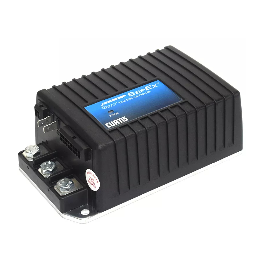
- Page 6 FIGURES FIGURES . 1: Curtis 1243 2 electronic motor controller ......1 . 2: Mounting dimensions, Curtis 1243 2 controller ....4 . 3: Basic wiring configuration, Curtis 1243 2 controller ..7 . 4: Wiring for 5kΩ–0 throttle (“Type 1”) ........10 .
- Page 7 TABLES . 19: Throttle maps for controller with maximum speed set at 90% and creep speed set at 10% ............ 37 . 20: Field current relative to armature current, with field map parameter set at 50% and 20% ...... 39 .
-
Page 8: Overview
1 — OVERVIEW OVERVIEW Curtis 1243 Generation 2 MultiMode™ controllers are separately excited motor speed controllers designed for use in a variety of small industrial vehicles and in material handling equipment. These programmable controllers are simple to install, efficient, and cost effective, while offering more features than the original 1243. - Page 9 1 — OVERVIEW Like all Curtis motor controllers, the 1243 2 offers superior operator control of the vehicle’s motor drive speed. Features include: ✓ Interlock braking with load sensor to meet required braking distance without unnecessary harsh braking at light loads ✓...
- Page 10 1 — OVERVIEW ✓ Linear cutback of regenerative braking current during overvoltage ✓ High pedal disable (HPD) and static return to off (SRO) interlocks prevent vehicle runaway at startup ✓ Internal and external watchdog circuits ensure proper software operation ✓ Fully protected inputs and short-circuit protected output drivers. Curtis Model 840 Spyglass Display [optional] ✓...
-
Page 11: Installation And Wiring
2 — INSTALLATION & WIRING: Controller INSTALLATION AND WIRING MOUNTING THE CONTROLLER The controller can be oriented in any position, but the location should be carefully chosen to keep the controller as clean and dry as possible. If a clean, dry mounting location cannot be found, a cover must be used to shield the controller from water and contaminants. - Page 12 2 — INSTALLATION & WIRING: Controller The mounting surface must be at least a 300 3 mm (12" 12" 1/8") × × × × aluminum plate, or its equivalent, and subjected to a minimum 3 mph airflow to meet the specified time/current ratings. Although not usually necessary, a thermal joint compound can be used to improve heat conduction from the controller heatsink to the mounting surface.
-
Page 13: Connections: Low Current
2 — INSTALLATION & WIRING: Controller CONNECTIONS Low Current Connections A 16-pin Molex low current connector in the controller provides the low current logic control connections: load sensor input [optional] Pin 1 Fault 1 output / pump input Pin 2 Fault 2 output Pin 3 main contactor driver output... -
Page 14: Wiring: Controller
2 — INSTALLATION & WIRING: Controller for the M8 bolts. The maximum bolt insertion depth below the surface of the bus bar is 1.3 cm (1/2"). Bolt shafts exceeding this length may damage the controller. The torque applied to the bolts should not exceed 16.3 N·m (12 ft-lbs). Two 1/4"... - Page 15 2 — INSTALLATION & WIRING: Controller Standard Power Wiring Motor armature wiring is straightforward, with the armature’s A1 connection going to the controller’s bus bar and the armature’s A2 connection going to the controller’s bus bar. The motor’s field connections (S1 and S2) are less obvious. The direction of vehicle travel with the forward direction selected will depend on how the motor’s S1 and S2 connections are made to the controller’s two field terminals ) and how the motor shaft is connected to the drive wheels through...
-
Page 16: Wiring: Throttle
2 — INSTALLATION & WIRING: Throttle WIRING: Throttle Wiring for various throttles is described below. They are categorized as Type 1, 2, 3, and 4 throttles in the program menu of the handheld programmer. Note: In the text, throttles are identified by their nominal range and not by their actual active range. -
Page 17: 5Kω-0, 2-Wire Potentiometer Throttle ("Type 1")
2 — INSTALLATION & WIRING: Throttle 5kΩ–0 Throttle (“Type 1”) The 5kΩ–0 throttle (called a “Type 1” throttle in the programming menu of the 13XX programmer) is a 2-wire resistive throttle that connects between the Pot Wiper and Pot Low pins (Pins 6 and 7), as shown in Figure 4. It doesn’t matter which wire goes on which pin. -
Page 18: And Electronic Throttles ("Type 2")
2 — INSTALLATION & WIRING: Throttle 0–5V, Current Source, 3-Wire Potentiometer, and Electronic Throttles (“Type 2”) With these throttles (“Type 2” in the programming menu) the controller looks for a voltage signal at the wiper input (Pin 6). Zero speed will correspond to 0 V and full speed to 5 V (measurements made relative to B-). -
Page 19: Fig. 7 Wiring For Current Source Throttle ("Type 2")
2 — INSTALLATION & WIRING: Throttle Current Sources As Throttles A current source can also be used as a throttle input, wired as shown in Figure 7. A resistor, R , must be used to convert the current source value to a voltage. throttle The resistor should be sized to provide a 0–5V signal variation over the full current range. -
Page 20: 0-5Kω, 2-Wire Potentiometer Throttle ("Type 3")
2 — INSTALLATION & WIRING: Throttle Curtis ET-XXX Electronic Throttle The Curtis ET-XXX provides a 0–5V throttle and forward/reverse inputs for the 1243 2 controller. Wiring for the ET-XXX is shown in Figure 9. When an electronic throttle is used, the Pot Low Fault parameter (see Section 3, page 38) must be set to Off;... -
Page 21: Wigwag 0-5V And 3-Wire Pot Throttles
2 — INSTALLATION & WIRING: Throttle Wiring for Fig. 10 0–5k Ω throttle Pot Wiper input (Pin 6) (“Type 3”). FASTER Pot Low input (Pin 7) 0–5kΩ a throttle fault is generated and the controller is disabled. Note: The Pot Low pin (Pin 7) must not be tied to ground (B-). -
Page 22: Wiring: Spyglass Display
2 — INSTALLATION & WIRING: Spyglass Display Wiring for fault Fig. 11 outputs, when used to drive LEDs. Alternatively, Pin 2 can be used for a pump Fault 1 output (Pin 2) meter input, and Pin 3 can be used to interface an Fault 2 output (Pin 3) external enable circuit. -
Page 23: Wiring: Emergency Reverse
2 — INSTALLATION & WIRING: Emerg. Reverse and Aux Driver WIRING: Emergency Reverse To implement the emergency reverse feature, Pin 13 (the emergency reverse input) must be connected to battery voltage as shown in the standard wiring diagram, Figure 3. The controller provides maximum braking torque as soon as the emer- gency reverse switch is closed. -
Page 24: Contactor, Switches, And Other Hardware
2 — INSTALLATION & WIRING: Main Contactor & Switches, etc. CONTACTOR, SWITCHES, and OTHER HARDWARE Main Contactor A main contactor should be used with any 1243 2 controller; otherwise the controller’s fault detects will not be able to fully protect the controller and motor drive system from damage in a fault condition. -
Page 25: Table 2 Mode Selection
2 — INSTALLATION & WIRING: Switches, etc. Circuitry Protection Devices To protect the control circuitry from accidental shorts, a low current fuse (appropriate for the maximum current draw) should be connected in series between the battery and KSI. Additionally, a high current fuse should be wired in series with the main contactor to protect the motor, controller, and batteries from accidental shorts in the power system. -
Page 26: Programmable Parameters
3 — PROGRAMMABLE PARAMETERS PROGRAMMABLE PARAMETERS The 1243 2 controller has a number of parameters that can be programmed using a Curtis handheld programmer. These programmable parameters allow the vehicle’s performance characteristics to be customized to fit the needs of individual vehicles or vehicle applications. - Page 27 3 — PROGRAMMABLE PARAMETERS Battery Parameter Field Parameters Hourmeter p.21 p.38 ..........Parameters p.45 ....Battery Voltage Min. Field Current Limit Adjust Hours High Max. Field Current Limit Acceleration Parameters p.21 .... Adjust Hours Middle Field Map Start Adjust Hours Low Drive Current Limit, M1–M4 Field Map Set Total Hours...
-
Page 28: Battery Parameter
3 — PROGRAMMABLE PARAMETERS: Battery & Acceleration Parameters Battery Parameter VOLTAGE The battery voltage parameter sets the overvoltage and undervoltage protection thresholds for the controller and battery. Overvoltage protection cuts back regenerative braking to prevent damage to batteries and other electrical system components due to overvoltage;... -
Page 29: Current Ratio
3 — PROGRAMMABLE PARAMETERS: Braking Parameters mode. If the controller is in braking mode, the quick start function is disabled, allowing normal braking to occur. Quick start is adjustable from 0 to 10. Increasing the value will “liven” the vehicle’s acceleration response to fast throttle movements. -
Page 30: Braking Parameters
3 — PROGRAMMABLE PARAMETERS: Braking Parameters Braking Parameters The seven Braking parameters affect the regenerative braking that is initiated when the throttle is reduced or when the direction is reversed while the vehicle is being driven. During regen braking, armature current flows toward the battery. M1–M4, BRAKE C/L The braking current limit parameter adjusts the maximum current the controller will supply to the motor during regen braking. -
Page 31: Braking Rate, M1-M4
3 — PROGRAMMABLE PARAMETERS: Braking Parameters At zero throttle, the restraint function tries to keep the motor at zero speed, which helps hold the vehicle from running away down ramps. The higher the restraint parameter value, the stronger the braking force applied to the motor and the slower the vehicle will creep down ramps. -
Page 32: Taper Rate
3 — PROGRAMMABLE PARAMETERS: Braking Parameters TAPER RATE The taper rate affects direction-reversal at the very end of braking, just before the vehicle stops moving in the original direction. Low taper rate values result in faster, more abrupt direction transitions. Higher taper rate values result in slower and smoother direction transitions. -
Page 33: Interlock Braking Parameters
3 — PROGRAMMABLE PARAMETERS: Interlock Braking Parameters Interlock Braking Parameters If the interlock switch opens while the vehicle is being driven, the controller uses the motor to apply regenerative braking as soon as the programmed Sequencing Delay (see page 42) expires. This braking—which is called interlock braking—greatly reduces wear on the electromagnetic brake and also enables the vehicle to meet more stringent stopping distance requirements. -
Page 34: Min. Forward Regen
3 — PROGRAMMABLE PARAMETERS: Interlock Braking Parameters If your application will have widely varying loads, we recommend that you include a load sensor (at Pin 1). The use of a load sensor can prevent unnecessarily harsh braking at light loads, which may lock up the wheels. MIN FWD REGEN [applicable only with optional load sensor] The minimum forward regen parameter defines the maximum regenerative... -
Page 35: Electromagnetic Brake Parameters
3 — PROGRAMMABLE PARAMETERS: Electromagnetic Brake Parameters Electromagnetic Brake Parameters The four Electromagnetic Brake parameters—along with the sequencing delay— affect the behavior of the auxiliary driver at Pin 8. This driver is typically used for an electromagnetic brake, as shown in the basic wiring diagram (Figure 3, page 7). See Figure 14 for an illustration of the relationship between interlock braking, the EM brake, and the sequencing, auxiliary, and interlock braking delays. -
Page 36: 14: Electromagnetic Brake Parameters, In The Context Of The Four Delay Parameters
3 — PROGRAMMABLE PARAMETERS: Electromagnetic Brake Parameters The electromagnetic Fig. 14 INTERLOCK brake parameters, in the SWITCH context of the 1243 OPENS controller’s four delay parameters (sequencing, interlock brake, main Sequencing Delay HPD fault (HPD Type 1) contactor open, and aux SRO fault (0.0 –... - Page 37 3 — PROGRAMMABLE PARAMETERS: Electromagnetic Brake Parameters Table 3 CONFIGURATION OPTIONS: AUXILIARY DRIVER (Pin 8) TYPE DESCRIPTION OF OPERATION Aux driver disabled. Electromagnetic brake used like a parking brake. • The brake is released when the interlock switch closes. • The brake is engaged as follows: Interlock The aux driver engages the brake when the interlock switch opens and (a) the programmed Sequencing Delay and Interlock Brake Delay expire or (b) the motor speed nears zero, whichever happens first.
-
Page 38: Speed Parameters
3 — PROGRAMMABLE PARAMETERS: Speed Parameters Speed Parameters M1–M4, MAX FWD SPD The maximum forward speed parameter defines the maximum controller voltage output at full throttle, in the forward direction. The maximum forward speed parameter is adjustable from the programmed creep speed up to 100%. It is tuned as part of the vehicle performance adjustment process (Section 5). -
Page 39: Throttle Parameters
3 — PROGRAMMABLE PARAMETERS: Throttle Parameters Throttle Parameters THROTTLE TYPE The 1243 2 controller accepts a variety of throttle inputs. Instructions are provided in Section 2 for wiring the most commonly used throttles: 5kΩ–0 and 0–5kΩ 2-wire potentiometers, 3-wire potentiometers, 0–5V throttles, current sources, and the Curtis ET-XXX electronic throttle. -
Page 40: Fig. 15 Effect Of Adjusting The Throttle Deadband Parameter
3 — PROGRAMMABLE PARAMETERS: Throttle Parameters Effect of adjusting Fig. 15 Throttle Type 1 (5kΩ–0) the Throttle Deadband parameter. 40% Deadband 0.2V 2.1V (0Ω) (3.0kΩ) 10% Deadband 3.0V 0.2V (4.5kΩ) (0Ω) 0% Deadband 0.2V 3.3V (0Ω) (5.0kΩ) Throttle Type 2 (0–5V, single-ended) 40% Deadband 2.1V 10% Deadband... -
Page 41: Throttle Max
3 — PROGRAMMABLE PARAMETERS: Throttle Parameters THROTTLE MAX The throttle max parameter sets the wiper voltage or resistance required to produce 100% controller output. Decreasing the throttle max setting reduces the wiper voltage or resistance and therefore the full stroke necessary to produce full controller output. - Page 42 3 — PROGRAMMABLE PARAMETERS: Throttle Parameters Fig. 16, cont. Throttle Type 3 (0–5kΩ) Effect of adjusting the 0.2V (0Ω) Throttle Max parameter 100% Throttle Max (throttle types 3 and 4). 40% Deadband 1.4V 3.3V (2.0kΩ) (5.0kΩ) 90% Throttle Max 40% Deadband 1.4V 3.0V (2.0kΩ)
-
Page 43: Throttle Map
3 — PROGRAMMABLE PARAMETERS: Throttle Parameters THROTTLE MAP The throttle map parameter modifies the vehicle’s response to the throttle input. The throttle map parameter’s default setting of 50% provides a linear output response to throttle position. Values below 50% reduce the controller output at low throttle, providing enhanced slow speed maneuverability. -
Page 44: Throttle Maps For Controller With Maximum Speed Set At 100% And Creep Speed Set At 10
3 — PROGRAMMABLE PARAMETERS: Throttle Parameters Increasing the creep speed value adds to the applied throttle and simply shifts the curves up. As shown in Figure 18, a creep speed setting of 10% with the Throttle Map set at 50% gives 60% PWM output (50% + 10%) at half throttle. -
Page 45: Pot Low Fault
3 — PROGRAMMABLE PARAMETERS: Field Parameters POT LOW FAULT The pot low fault parameter allows the controller’s pot low fault detection to be disabled. This is useful when single-wire, ground (B-) referenced voltage throttle inputs are used. Setting the pot low fault parameter to Off disables the fault detection at the pot low input (Pin 7). -
Page 46: Field Map
3 — PROGRAMMABLE PARAMETERS: Field Parameters FIELD MAP The field map defines the relationship between armature current and field current under steady-state drive conditions. The shape of the field map is determined by the programmed Field Min, Field Max, Field Map, Field Map Start, and M1-M4 Drive C/L settings. -
Page 47: Field Check
3 — PROGRAMMABLE PARAMETERS: Main Contactor Parameters FIELD CHECK The field check parameter determines whether the field diagnostics will be active. When programmed On, the controller checks for field open and field shorted faults. This parameter is typically programmed On except in series motor applications, or where the motor resistance is too high to provide valid fault data. -
Page 48: Sequencing Fault Parameters
3 — PROGRAMMABLE PARAMETERS: Sequencing Fault Parameters Sequencing Fault Parameters ANTI-TIEDOWN The anti-tiedown feature prevents operators from taping or “tying down” the mode select switches in order to operate permanently in Mode 2 or Mode 4 (which are typically the higher speed modes). Each time the interlock switch closes, the anti-tiedown feature checks which mode is selected. -
Page 49: Static Return To Off (Sro)
3 — PROGRAMMABLE PARAMETERS: Sequencing Fault Parameters throttle is applied after the KSI input has been received but before the interlock switch is closed, the vehicle will accelerate to the requested speed as soon as the interlock switch is closed. The static return to off (SRO) feature prevents the vehicle from being started when “in gear,”... -
Page 50: Emergency Reverse Parameters
3 — PROGRAMMABLE PARAMETERS: Emergency Reverse Parameters momentarily cycled during operation. However, it is important to bear in mind that the same sequencing delay also delays the initiation of interlock braking (see Figure 14, page 29). The sequencing delay can be programmed from 0.0 to 3.0 seconds, with 0.0 corresponding to no delay. -
Page 51: Motor Protection Parameters
3 — PROGRAMMABLE PARAMETERS: Motor Protection Parameters Motor Protection Parameters The 1243 2 controller can protect the motor from damage due to overtemperature by cutting back the motor speed. An estimate of the motor temperature is derived from the resistance of the field winding. The controller measures field current, field PWM, and battery voltage, and uses these measurements to calculate the instantaneous field resistance. -
Page 52: Hourmeter Parameters
3 — PROGRAMMABLE PARAMETERS: Hourmeters Hourmeter Parameters Two individual hourmeters are built into the 1243 2 controller, each with non- volatile memory: • a total hourmeter, that measures the total operating time (KSI on-time), and • a traction hourmeter, that measures the time that a direction is selected. Each hourmeter has a corresponding service timer and disable timer. -
Page 53: Set Traction Hours
3 — PROGRAMMABLE PARAMETERS: Hourmeters Once the preset values have been loaded, the Set Total Hours parameter should be programmed Off. SET TRAC HRS The set traction hours parameter is used to apply preset high, middle, and low values to the traction hourmeter. First, adjust the preset values as desired for the traction hourmeter. -
Page 54: Traction Fault Speed
3 — PROGRAMMABLE PARAMETERS: Hourmeters Setting the parameter to 0 means that the traction disable timer will never expire and therefore never invoke the traction fault speed. TRAC FAULT SPD The traction fault speed parameter sets the maximum drive speed in the event the traction disable timer expires or the total disable timer expires;... -
Page 55: Hourmeter Type
3 — PROGRAMMABLE PARAMETERS: Hourmeters Other Hourmeter Parameters HOURMETER TYPE The Spyglass gauge displays hourmeter data for 5 seconds each time the keyswitch is turned on. The hourmeter type parameter defines whether the total hourmeter or traction hourmeter data will be displayed. When this parameter is programmed On, the total hourmeter is displayed;... -
Page 56: Battery Discharge Indicator (Bdi) Parameters
3 — PROGRAMMABLE PARAMETERS: Battery Discharge Indicator (BDI) Parameters The battery discharge indicator constantly calculates the battery state-of-charge whenever KSI is on. When KSI is turned off, the present battery state-of-charge is stored in non-volatile memory. BDI information is viewable via the Spyglass display and via the 1311 programmer’s Monitor Menu as BDI%. -
Page 57: Battery Adjust
3 — PROGRAMMABLE PARAMETERS: Table 5 STANDARD BATTERY VOLTAGES FOR FLOODED LEAD ACID AND SEALED MAINTENANCE-FREE BATTERIES 24V BATTERY 36V BATTERY PARAMETER FLOODED SEALED FLOODED SEALED Full volts 24.5 V 24.5 V 36.7 V 36.7 V (2.04 × 12) (2.04 × 12) (2.04 ×... -
Page 58: Fault Code Parameters
3 — PROGRAMMABLE PARAMETERS: Fault Code Parameters Fault Code Parameters FAULT CODE The 1243 2 controller has two fault outputs, at Pins 2 and 3, which can be used to transmit signals to LEDs located on the display panel or on any remote panel. -
Page 59: Controller Cloning
3 — PROGRAMMABLE PARAMETERS: Controller Cloning CONTROLLER CLONING Once a controller has been programmed to the desired settings, these settings can be transferred as a group to other controllers, thus creating a family of “clone” controllers with identical settings. Note: Cloning only works between controllers with the same model number and software version. -
Page 60: Installation Checkout
4 — INSTALLATION CHECKOUT INSTALLATION CHECKOUT Before operating the vehicle, carefully complete the following checkout proce- dure. If you find a problem during the checkout, refer to the diagnostics and troubleshooting section (Section 7) for further information. The installation checkout can be conducted with or without a program- mer. - Page 61 4 — INSTALLATION CHECKOUT switch wiring is correct, turn off the controller, disconnect the battery, and exchange the motor’s field connections ( ) on the control- ler. The motor should now turn in the proper direction. The motor should run proportionally faster with increasing throttle. ☞...
-
Page 62: Vehicle Performance Adjustment
5 — VEHICLE PERFORMANCE ADJUSTMENT VEHICLE PERFORMANCE ADJUSTMENT The 1243 2 controller is a very powerful vehicle control system. Its wide variety of adjustable parameters allow many aspects of vehicle performance to be optimized. This section provides explanations of what the major tuning parameters do and instructions on how to use these parameters to optimize the performance of your vehicle. - Page 63 5 — VEHICLE PERFORMANCE ADJUSTMENT -A Tuning the Throttle Deadband 1. Jack the vehicle wheels up off the ground so that they spin freely. STEP 2. Plug the programmer into the controller and turn on the key- STEP switch and interlock switch (if used). 3.
- Page 64 5 — VEHICLE PERFORMANCE ADJUSTMENT -B Tuning the Throttle Max 1. Jack the vehicle wheels up off the ground so that they spin freely. STEP 2. Plug the programmer into the controller and turn on the key- STEP switch and interlock switch (if used). 3.
-
Page 65: Tuning The Controller To The Motor
5 — VEHICLE PERFORMANCE ADJUSTMENT Tuning the Controller to the Motor The 1243 2 controller has the flexibility to be tuned to nearly any separately excited motor from any manufacturer. The programmable parameters allow full control of the motor’s maximum armature current during driving and braking and full control of the motor’s maximum and minimum field current as well as the field current relationship to the armature current. - Page 66 5 — VEHICLE PERFORMANCE ADJUSTMENT low battery voltage and with a hot motor. To determine this value, divide the low battery voltage (typically 70% of nominal) by the high temperature field winding resistance specification provided by the manufacturer. Set the Field Max parameter to this value.
-
Page 67: Setting The Unloaded Vehicle Top Speed
5 — VEHICLE PERFORMANCE ADJUSTMENT Setting the Vehicle’s Unloaded Top Speed The controller and vehicle should be configured as follows prior to setting the maximum unloaded vehicle speed: • Max Speed = 100%, all modes • Drive Current Limit as established in tuning procedure 2 •... -
Page 68: Equalizing Loaded And Unloaded Vehicle Speed
5 — VEHICLE PERFORMANCE ADJUSTMENT 5. For Walkie/Rider Applications: Typically, different top speeds are STEP desired for walkie and rider operation. To tune a walkie/rider vehicle’s top speed, first tune it for rider operation by using the Field Min parameter. Then, to set the top speed for walkie operation, leave the Field Min parameter alone and decrease the Max Speed parameter until the desired walking vehicle speed is reached. -
Page 69: Fine Tuning
5 — VEHICLE PERFORMANCE ADJUSTMENT (ii) Set the Field Map Start parameter slightly higher than the observed armature current value. (iii) Load the vehicle and drive it on flat ground with full throttle applied. Further adjustments to the vehicle’s loaded speed can now be made by varying the Field Map parameter. -
Page 70: Response To Increased Throttle
5 — VEHICLE PERFORMANCE ADJUSTMENT 2. The default Restraint setting (5 amps) should work well for most STEP vehicles. If the vehicle exhibits excessive overspeed when driving down a ramp, increase the Restraint value. If the vehicle “speed hunts” while driving down a ramp or brakes too abruptly at low or released throttle, decrease the Restraint value. -
Page 71: Ramp Climbing
5 — VEHICLE PERFORMANCE ADJUSTMENT 2. If the transition is too abrupt: increase the Taper Rate and/or set STEP the Variable Braking parameter to On. Secondary adjustments can be made by increasing the Accel Rate. 3. If the transition is too slow: decrease the Taper Rate and set STEP Creep Speed to 5% or greater. -
Page 72: Programmer Menus
6 — PROGRAMMER MENUS: Program Menu PROGRAMMER MENUS The universal handheld Curtis programmers allow you to program, test, and diagnose Curtis programmable controllers. For information about 1311 pro- grammer operation, see Appendix B. If you are using the older 1307 program- mer, consult your existing documentation if necessary. - Page 73 6 — PROGRAMMER MENUS: Program Menu Program Menu, cont’d M2 MAX REV SPD Mode 2 maximum reverse speed, as % drive output Mode 3 maximum reverse speed, as % drive output M3 MAX REV SPD Mode 4 maximum reverse speed, as % drive output M4 MAX REV SPD CREEP SPEED Creep speed, as % drive output...
- Page 74 6 — PROGRAMMER MENUS: Program Menu Program Menu, cont’d ADJ HRS LOW Hourmeter preset low byte: 0–99 Hourmeter preset middle byte: 0–99 ADJ HRS MID Hourmeter preset high byte: 0–99 ADJ HRS HIGH SET TOTL HRS Apply preset values to total hourmeter: On or Off Apply preset values to traction hourmeter: On or Off SET TRAC HRS HOURMETER TYPE...
- Page 75 6 — PROGRAMMER MENUS: Program Menu Program Menu Notes Throttle types (for detail, see Throttle Wiring in Section 2) Type 1: 5kΩ–0 potentiometers Type 2: single-ended 0–5V, 3-wire pot, current source, and electronic throttles Type 3: 0–5kΩ potentiometers Type 4: wigwag 0–5V and 3-wire pot throttles HPD types (for detail, see Section 3: Programmable Parameters, page 41) Type 0: no HPD Type 1: HPD fault unless KSI and interlock inputs are received before a...
-
Page 76: Gen 2 Monitor Menu
6 — PROGRAMMER MENUS: Test/Monitor Menu 1243 2 MONITOR MENU Throttle reading, as % of full throttle THROTTLE % Motor field current, in amps FIELD CURRENT Motor armature current, in amps ARM CURRENT Motor field applied duty cycle, as % FIELD PWM ARM PWM Motor armature applied duty cycle, as %... -
Page 77: Gen 2 System Faults Menu
6 — PROGRAMMER MENUS: Diagnostics/Faults Menu 1243 2 SYSTEM FAULTS MENU This is a list of the possible fault messages you may see displayed by the programmer. The messages are listed here in alphabetical order for easy refer- ence. Mode Select 1 switch closed at startup ANTI-TIEDOWN FIELD SHORT Contactor coil or motor field winding shorted... -
Page 78: Diagnostics And Troubleshooting
7 — DIAGNOSTICS & TROUBLESHOOTING DIAGNOSTICS AND TROUBLESHOOTING The 1243 2 controller provides diagnostics information to assist technicians in troubleshooting drive system problems. The diagnostics information can be obtained by observing the appropriate display on the handheld programmer, the fault message displayed on the Spyglass gauge, the fault codes issued by the Status LED, or the fault display driven by the controller’s fault outputs (Fault 1 and Fault 2). -
Page 79: Table 7 Troubleshooting Chart
7 — DIAGNOSTICS & TROUBLESHOOTING Table 7 TROUBLESHOOTING CHART PROGRAMMER FAULT CATEGORY CODE LCD DISPLAY POSSIBLE CAUSE FAULT CLEARANCE NO KNOWN FAULTS CURRENT SHUNT FAULT 1. Abnormal vehicle operation causing Cycle KSI. If problem high current spikes. persists, replace controller. 2. -
Page 80: Fig . 21: Curtis 840 Spyglass, 3-Led And 6-Led Models
7 — DIAGNOSTICS & TROUBLESHOOTING Table 7 TROUBLESHOOTING CHART, cont’d PROGRAMMER FAULT CATEGORY CODE LCD DISPLAY POSSIBLE CAUSE FAULT CLEARANCE LOW BATTERY VOLTAGE 1. Battery voltage < undervoltage cutback. When voltage rises above 2. Corroded battery terminal. undervoltage cutoff point. 3. -
Page 81: Status Led Diagnostics
7 — DIAGNOSTICS & TROUBLESHOOTING STATUS LED DIAGNOSTICS A Status LED is built into the 1243 2 controller. It is visible through a window in the label on top of the controller. This Status LED displays fault codes when there is a problem with the controller or with the inputs to the controller. -
Page 82: Fault Output Led Diagnostics
7 — DIAGNOSTICS & TROUBLESHOOTING FAULT OUTPUT LED DIAGNOSTICS The 1243 2 controller provides two fault outputs designed to transmit fault information to LEDs located on the display panel or on any remote panel. These outputs can be programmed to display faults in Fault Code format or in Fault Category format—see Section 3, page 51. -
Page 83: Controller Maintenance
8 — MAINTENANCE CONTROLLER MAINTENANCE There are no user serviceable parts in the Curtis 1243 2 controller. No attempt should be made to open, repair, or otherwise modify the controller. Doing so may damage the controller and will void the warranty. It is recommended that the controller be kept clean and dry and that its fault history file be checked and cleared periodically. -
Page 84: Electromagnetic Compatibility (Emc
APPENDIX A: EMC & ESD DESIGN CONSIDERATIONS APPENDIX A VEHICLE DESIGN CONSIDERATIONS REGARDING ELECTROMAGNETIC COMPATIBILITY (EMC) AND ELECTROSTATIC DISCHARGE (ESD) ELECTROMAGNETIC COMPATIBILITY (EMC) Electromagnetic compatibility (EMC) encompasses two areas: emissions and immunity. Emissions are radio frequency (rf ) energy generated by a product. This energy has the potential to interfere with communications systems such as radio, television, cellular phones, dispatching, aircraft, etc. - Page 85 APPENDIX A: EMC & ESD DESIGN CONSIDERATIONS Increasing Immunity Immunity to radiated electric fields can be achieved either by reducing the overall circuit sensitivity or by keeping the undesired signals away from this circuitry. The controller circuitry itself cannot be made less sensitive, since it must accurately detect and process low level signals from the throttle potenti- ometer.
- Page 86 APPENDIX A: EMC & ESD DESIGN CONSIDERATIONS applied to the base material. If the ohmic contact itself is not continuous, the shielding effectiveness can be maximized by making the joints between adjacent pieces overlapping rather than abutted. The shielding effectiveness of an enclosure is further reduced when a wire passes through a hole in the enclosure.
-
Page 87: Curtis 1311 Handheld Programmer
APPENDIX A: EMC & ESD DESIGN CONSIDERATIONS APPENDIX B: 1311 PROGRAMMER APPENDIX B CURTIS 1311 HANDHELD PROGRAMMER The Curtis 1311 handheld programmer provides programming, diagnostic, and test capabilities for the 1243 2 controller. The power for operating the programmer is supplied by the host controller via a 4-pin Molex connector. The programmer includes a 7-line alphanumeric LCD display, rocker- type keys for navigating through the display and for modifying parameters (+/ -), and three keys that can be used as bookmarks. - Page 88 APPENDIX A: EMC & ESD DESIGN CONSIDERATIONS APPENDIX B: 1311 PROGRAMMER The bookmark keys allow you to quickly go back to up to three selected items without having to navigate back through the menu structure. To set a bookmark, press one of the bookmark keys for about three seconds, until the Bookmark Set screen is displayed.
-
Page 89: Programmable Parameters Index
APPENDIX C: PROGRAMMABLE PARAMETERS INDEX APPENDIX A: EMC & ESD DESIGN CONSIDERATIONS APPENDIX C PROGRAMMABLE PARAMETERS INDEX The 1243 2 controller’s programmable parameters are listed below in alphabetical order (by programmer display name), with references provided to the main entry in the manual. page 21 MAIN CONT INTR page 40... -
Page 90: Specifications
APPENDIX A: EMC & ESD DESIGN CONSIDERATIONS APPENDIX D: SPECIFICATIONS APPENDIX D SPECIFICATIONS Table D-1 SPECIFICATIONS: 1243 2 CONTROLLER Nominal input voltage 24 –36 V PWM operating frequency 16 kHz Electrical isolation to heatsink 500 V ac (minimum) KSI input voltage (minimum) 16.8 V KSI input current (no contactors engaged) 78 mA without programmer;...
Need help?
Do you have a question about the MultiMode 1243 Generation 2 and is the answer not in the manual?
Questions and answers