
Related Manuals for Control Techniques UD77


Summary of Contents for Control Techniques UD77
- Page 1 User Guide UD77 DeviceNet Option Module For Unidrive Part Number: 0460-0077 Issue Number: 2...
- Page 2 Copyright © January 2001 Control Techniques SSPD Author Paul Bennett Issue Code Issue 2 System File V2.07.03 or later...
-
Page 3: Table Of Contents
Contents Introduction DeviceNet Interface for Unidrive Product Conformance Certification Overview Specification Mechanical Installation Unidrive Electrical Installation DeviceNet Connectors DeviceNet Connections DeviceNet Cable DeviceNet Cable Screen Connections DeviceNet Network Termination Maximum Network Length External Power Supply Getting Started Basic Communications Quick Start DeviceNet Node Address DeviceNet Data Rate Product Code Elaboration... - Page 4 Support Files What are EDS Files? Generic EDS Files EDS File Revisions Advanced EDS Files Diagnostics Fieldbus Code Firmware Version System File Version Node Address Network Data Rate Number of Network Messages Node Status Network Status No Data Transfer 8.10 Unidrive Trip Codes Advanced Features Network Loss Trip...
- Page 5 9.12.6 TorqueActual 9.12.7 TorqueRef 9.13 Motor Data Object 9.13.1 MotorType 9.13.2 RatedCurrent 9.13.3 RatedVoltage 9.14 Control Techniques Object Quick Reference 10.1 Complete Parameter Reference 10.2 DeviceNet Data Format 10.3 Fieldbus Control Word 10.4 Fieldbus Status Word 10.5 Unidrive Trip Codes...
-
Page 7: Introduction
Introduction NOTE Unidrive parameters are denoted in this manual by “#MM.PP”, where MM refers to the menu number, and PP refers to the parameter number within that menu. Please refer to the Unidrive Advanced User Guide for a full list of parameter definitions. DeviceNet Interface for Unidrive The Unidrive DeviceNet interface is supplied as an option module, with the DeviceNet using a UD70 as the host. -
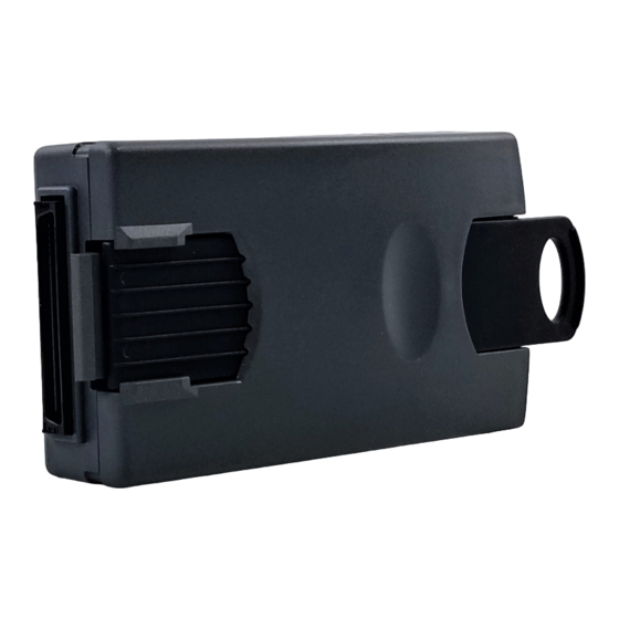
Page 8: Mechanical Installation
Mechanical Installation The Unidrive must be disconnected from the mains supply before installing or removing an option module. Warning Unidrive Slide the option module into the Unidrive. Push the option module into the Unidrive until it clicks into place. Issue Number: 2... -
Page 9: Electrical Installation
Electrical Installation DeviceNet Connectors The Unidrive DeviceNet Interface provides a standard 5-way screw terminal socket (A) to connect to the DeviceNet network. A small converter board in provided to convert from the 9-way D-type connector Connectors C and D on the Unidrive DeviceNet interface are the RS232 (C) and RS485 (D) ports of the UD70. -
Page 10: Devicenet Connections
Association site “www.odva.org”. NOTE The Open DeviceNet Vendors Association and Control Techniques can only guarantee correct and reliable operation of a DeviceNet network if all components (including the network cable) installed have full Product Conformance Certification from the ODVA. DeviceNet Cable Screen Connections The Unidrive DeviceNet interface should be wired with the cable shields isolated from earth at each Drive. -
Page 11: Devicenet Network Termination
DeviceNet Network Termination There is no termination resistor supplied on the Unidrive DeviceNet interface. It is the user’s responsibility to ensure that both ends of each section of network cable are correctly terminated. A 120Ω 0.25W resistor should be connected between the CAN_H and CAN_L lines at each end of the main trunk cable, as shown in the diagram below. -
Page 12: Maximum Network Length
Maximum Network Length The data rate that can be used depends mainly on the length of cable that is being used in the network, so the physical layout of the network must be considered during the network design stage of a project. Data Rate (bits/sec) 125K 250K... -
Page 13: Getting Started
Getting Started The Quick Start section shows the basic parameter configurations required for the DeviceNet interfaces to establish communications. Polled and Explicit data explanations are given in chapters 5 and 6. NOTE Parameters #20.01 to #20.20 and #20.50 are reserved for configuring the DeviceNet interface, and should not be used in DPL programs. -
Page 14: Devicenet Data Rate
DeviceNet Data Rate Unidrive: #20.08 All nodes on DeviceNet must be configured to run at the same data rate. The range of data rates available is shown in the table below. #20.08 Data Rate (bits/sec) 125K 250K 500K Product Code Elaboration Unidrive: #20.12 Ensure that this parameter is set to 0. -
Page 15: Node Status
Node Status Unidrive: #20.09 When the Unidrive is powered up, the DeviceNet interface will initialise the internal hardware, and go into the standby mode. The node will switch to “Operational” mode when the master controller starts communicating with the node. #20.09 Status Description Operational... -
Page 16: Network Loss Trip
Network Loss Trip Unidrive: #17.14 If the DeviceNet network stops operating, the interface will trip the Unidrive on "tr60". The default time delay between network loss and Unidrive trip is 48ms, so the actual delay to trip will be between 48ms and 96ms. -
Page 17: Polled Data
Polled Data The default DeviceNet configuration contains three 16-bit IN data words and three 16-bit OUT data words. These data words are classed as “polled data channels”. NOTE “OUT data” and “IN data” describe the direction of data transfer as seen by the PLC scanner. -
Page 18: Mapping Parameters On Unidrive
Mapping Parameters on Unidrive The mapping for the cyclic data channels on the Unidrive DeviceNet interface can be set from the Unidrive keypad using #20.PP parameters. The mapping method is similar to the method used for mapping analogue inputs and outputs. The value entered in the mapping parameter takes the form MMPP, where MM = menu number of the target parameter and PP = parameter number of the target parameter. -
Page 19: Storing Parameters
The 32-bit cyclic channel is configured by mapping IN or OUT polled data channel 1 (#20.06 or #20.07) to a 32 bit register. Channel 2 will contain the data high word (upper 16 bits of the 32-bit register), irrespective of the mapping value set for channel 2. If channel 2 is mapped to a 32-bit register, channel 2 will contain the data low word (lower 16 bits of the 32-bit register) and channel 3 will automatically contain the data high word. -
Page 20: Mapping Conflicts
triggered when an under-voltage (UU) trip occurs. Set #17.20 to 1, store the Unidrive parameters and reset the UD70 to enable this feature. Mapping Conflicts When the mapping parameters for the DeviceNet cyclic channels are set, care must be taken to ensure that there are no clashes with the mapping of the analogue and digital inputs within the Unidrive. -
Page 21: Fieldbus Control Word For Unidrive
Fieldbus Control Word for Unidrive NOTE This section assumes that the Unidrive is configured to use the default Wire Proof PLC sequencing mode (#6.04 = 4). If PLC mode is selected (#6.04 = 3), the control word mapping is slightly different. Refer to section 9.2 for details. - Page 22 The TRIP bit (b4) will cause a “tr52” trip when set to 1, but the trip cannot be cleared until the TRIP bit (b4) has been reset to 0. Parameters #18.31 to #18.33 are general user parameters and do not have mask bits.
-
Page 23: Fieldbus Status Word For Unidrive
Fieldbus Status Word for Unidrive The status word is an efficient way of remotely monitoring and diagnosing the status of the Unidrive. Each bit in the status word indicates the status of a function of the Unidrive, e.g. At Speed, Drive Healthy, etc. -
Page 24: Explicit Data
The method of using non-cyclic data will depend entirely on the type of scanner used to control the DeviceNet network. For this reason, Control Techniques is unable to offer any specific technical support with implementing non-cyclic data transfer on any particular DeviceNet scanner and PLC combination.. -
Page 25: Support Files
DeviceNet network. Refer to the software documentation for instructions on how to install EDS files. Control Techniques cannot provide specific technical support for any of these software packages. Issue Number: 2... -
Page 26: Eds File Revisions
EDS File Revisions The EDS files from Control Techniques have undergone several revisions as specifications have been changed or tightened up. The table below shows the compatibility with the most common DeviceNet configuration tools. DeviceNet RSNetworx Revision Manager Not compatible V2.xx.xx and earlier... -
Page 27: Diagnostics
Diagnostics The information from the parameters described below should always be noted before contacting Control Techniques for technical support. Fieldbus Code Unidrive: #20.14 The fieldbus code identifies the hardware level in the DeviceNet interface. This information is vital when trying to determine what upgrades can be performed on older modules. -
Page 28: System File Version
System File Version Unidrive: #17.02 The system file installed in the UD70 must be the correct file for the communications option installed. The system file for the Unidrive DeviceNet interface is “DNET.SYS”. The system file that must be installed can depend on the level of hardware and firmware in the module. -
Page 29: Node Status
Node Status Unidrive #20.09 The Node Status is indicated in #20.09. Status Node Description Status Device Device is operating correctly. Operational Device In On Mentor II, the speed feedback scaling Standby Mode parameter (#3.16) is set 0. This must be set to positive value to allow speed feedback to be scaled correctly. -
Page 30: Unidrive Trip Codes
8.10 Unidrive Trip Codes The trip codes listed below may be caused by the Unidrive DeviceNet interface. Other trips may occur if a DPL program is loaded. For a full list of UD70 trips, refer to the UD70 User Guide Trip Error Code... -
Page 31: Advanced Features
Advanced Features Network Loss Trip Unidrive: #20.11 0 = trip disabled 16 to 992 = trip delay time (in ms) The DeviceNet interface counts the number of valid network cycles received in a time period specified by #20.11. The trip is triggered if no messages are received in a given sample period, and messages were received in the previous sample period. -
Page 32: Unidrive Sequencing Mode
Unidrive Sequencing Mode 3 The default sequencing mode for Unidrive is the Wire-Proof PLC Mode. If PLC Mode is selected (#6.04 = 3), the sequencing bits (#6.30 - #6.32) have slightly different functions. Control Parameter Sequencing Bit PLC Mode Word (#6.04 = 3) #6.15 Enable... -
Page 33: Drive Reset Using The Devicenet Network
Drive Reset Using The DeviceNet Network The Unidrive control word does not provide a RESET bit to clear a trip condition in the Unidrive. There are three methods of resetting the Unidrive from the master controller via the DeviceNet network. 9.3.1 Reset Without DPL Code To implement a RESET function without using DPL code, one of the... -
Page 34: Reset Using Dpl Code
9.3.3 Reset Using DPL Code If both of the menu 9 logic functions within the Unidrive are being used, some DPL code can be used to monitor the control word, and reset the Unidrive. The code should be placed in the SPEED, ENCODER or CLOCK task to ensure frequent scanning of the RESET bit. -
Page 35: Event Task Trigger On Ud70
The input (attribute 101) and output (attribute 100) assembly objects are set in the Control Supervisor. The default assembly objects are the Control Techniques Input (106) and Output (107) objects, which allow each data word to be mapped using #20.PP parameters. -
Page 36: Basic Speed Control
There are 3 ways to select a pre-defined Input or Output assembly object: Use the PLC Explicit communications to write directly to the Control Supervisor. (See page 43 in DeviceNet User Guide Issue 1.) The relevant attributes are 100 (Output) and 101 (Input). Use the Class Instance Editor within RSNetworx to modify the Control Supervisor directly yourself. -
Page 37: Extended Speed Control
9.7.2 Extended Speed Control Output Assembly Object 21 The scanner must be configured for 4 Tx bytes (or 2 Tx words) if this output assembly object is selected. Word Function Word 0 Extended Control Word (See section 9.11) Word 1 Speed Reference (See section 9.11.13) The Extended Control Word uses a full 16-bit word, with the bits having functions as shown below. -
Page 38: Extended Speed And Torque Control
9.7.4 Extended Speed and Torque Control Output Assembly Object 23 The scanner must be configured for 6 Tx bytes (or 3 Tx words) if this output assembly object is selected. Word Function Word 0 Basic Control Word (See section 9.11) Word 1 Speed Reference (See section 9.11.13) Word 2... -
Page 39: Basic Speed And Torque Control
9.7.6 Basic Speed and Torque Control Input Assembly Object 72 The scanner must be configured for 6 Rx bytes (or 3 Rx words) if this input assembly object is selected. Word Function Word 0 Basic Status Word (See below) Word 1 SpeedActual (See section 9.12.4) Word 2 TorqueActual (See section 9.12.6) -
Page 40: Identity Object
Class: 1 (0x1) Instance: 1 (0x1) Attribute: 1 (0x1) The Vendor ID is a unique code assigned to each manufacturer of DeviceNet-compatible equipment by the Open DeviceNetVendors Association. The code for Control Techniques is 257. Action Value Comment Read 257 is the Vendor ID code assigned to Control Techniques 9.9.2... -
Page 41: Revision
All Control Techniques DeviceNet interfaces have a unique serial number stored in the non-volatile memory. 9.9.7 Product Name Class: 1 (0x1) Instance: 1 (0x1) Attribute: 7 (0x7) The Unidrive DeviceNet interface will return the string “UD77” when this attribute is read. Issue Number: 2... -
Page 42: Devicenet Object
9.10 DeviceNet Object Class: 3 (0x3) The DeviceNet Object provides the configuration and status of the Unidrive DeviceNet interface. All attributes are instance 1. Attribute Access Name Data Type Get/Set MAC-ID Byte Get/Set Baud Rate Byte Get/Set Bus Off Interrupt Byte Get/Set Bus Off Counter... -
Page 43: Bus Off Interrupt
9.10.3 Bus Off Interrupt Class: 3 (0x3) Instance: 1 (0x1) Attribute: 3 (0x3) Bus Off Interrupt (BOI) determines the action if the Bus Off state is encountered. The following values are supported (default value = 0) Value Action CAN chip is not reset. Manual reset of the device is required. -
Page 44: Control Supervisor Object
9.11 Control Supervisor Object Class: 41 (0x29) Manages drive functions such as start/stop and operational states. All attributes are instance 1. For each attribute, the READ and WRITE mappings are shown in the table. These are the actions that take place when each attribute is accessed. -
Page 45: Runrev
9.11.2 RunRev Class: 41 (0x29) Instance: 1 (0x1) Attribute: 4 (0x4) Set to 1 to start the drive, and run in reverse. Wire-proof PLC sequencing mode (#6.04 = 4) must be selected on the Unidrive. Action Mapping Read #6.32 Write (0) #90.11 = 0x1C00 Write (1) #90.11 = 0x1C08... -
Page 46: Ready
9.11.6 Ready Class: 41 (0x29) Instance: 1 (0x1) Attribute: 9 (0x9) Read only attribute that indicates that the drive is enabled and ready to run. Action Mapping Read #6.15 9.11.7 Faulted Class: 41 (0x29) Instance: 1 (0x1) Attribute: 10 (0xA) Read only attribute that indicates that the drive tripped when set to 1. -
Page 47: 9.11.10 Outputassembly
Attribute: 100 (0x64) The output assembly selected determines the format of the data that is transferred from the scanner to the drive. Four pre-defined DeviceNet output assemblies are supported, and a Control Techniques output assembly is also provided. (See section 9.7) Value... -
Page 48: 9.11.12 Driveenable
9.11.12 DriveEnable Class: 41 (0x29) Instance: 1 (0x1) Attribute: 102 (0x66) Control the software enable of the Unidrive. Both the software and hardware enable must be set before the Unidrive can run. Action Mapping Read #6.15 Write (0) #6.15 = 0 Write (1) #6.15 = 1 9.11.13 ZeroParam... -
Page 49: Atreference
9.12.1 AtReference Class: 42 (0x2A) Instance: 1 (0x1) Attribute: 3 (0x3) When set to 1, this attribute indicates that the motor is running at the demanded speed. Action Mapping Read #10.06 9.12.2 NetRef Class: 42 (0x2A) Instance: 1 (0x1) Attribute: 4 (0x4) This attribute selects the source of the speed reference for the drive. -
Page 50: Speedref
9.12.5 SpeedRef Class: 42 (0x2A) Instance: 1 (0x1) Attribute: 8 (0x8) This attribute provides the speed reference for the drive, when network reference is selected. (“rpm” is the value transmitted over DeviceNet.) Action Mapping Comment Read (OL) Converts Hz to rpm #2.01 #5.11 Read (CL or S) -
Page 51: Motortype
Control Techniques Object Class: 100 (0x64) This application specific object provides a means to access all parameters within a Control Techniques Drive. Each of the drive menus is modelled as an instance within this object; each parameter is an attribute of that instance. - Page 52 The table below indicates the number of instances supported and also the number of attributes within each instance. Instance Menu Number of Attributes Speed Reference Speed Ramps Speed Control Current Control Motor Control Sequencing Analogue I/O Digital I/O Logic Drive Status Drive Set-up Programmable Thresholds Position Control...
-
Page 53: Quick Reference
Quick Reference 10.1 Complete Parameter Reference Parameter Default Description #20.01 OUT Channel 2 Mapping #20.02 OUT Channel 3 Mapping #20.03 IN Channel 2 Mapping #20.04 IN Channel 3 Mapping #20.05 Node Address #20.06 9011 OUT Channel 1 Mapping #20.07 9011 IN Channel 1 Mapping #20.08 Data Rate... -
Page 54: Fieldbus Control Word
10.3 Fieldbus Control Word #18.33 #18.32 #18.31 #1.46 #1.45 TRIP ENABLE Function Description ENABLE Set to 1 to put the Unidrive in READY mode. (The hardware ENABLE must also be present.) The RUN FWD, JOG and RUN REV bits will have no effect unless the ENABLE bit is set to 1. -
Page 55: Fieldbus Status Word
10.4 Fieldbus Status Word #10.15 #10.14 #10.13 #10.12 #10.11 #10.10 #10.09 #10.08 #10.07 #10.06 #10.05 #10.04 #10.03 #10.02 #10.01 Parameter Description #10.01 Drive healthy #10.02 Drive running #10.03 Zero speed #10.04 Running at or below min speed #10.05 Below set speed #10.06 At speed #10.07... -
Page 56: Unidrive Trip Codes
10.5 Unidrive Trip Codes The trip codes listed below may be caused by the Unidrive DeviceNet interface. Other trips may occur if a DPL program is loaded. For a full list of UD70 trips, refer to the UD70 User Guide Trip Error Code...
Need help?
Do you have a question about the UD77 and is the answer not in the manual?
Questions and answers