National Instruments sbRIO-9607 User Manual
Single-board rio oem devices
Hide thumbs
Also See for sbRIO-9607:
- Getting started manual (14 pages) ,
- Getting started (14 pages) ,
- User manual (48 pages)
Table of Contents
Advertisement
USER MANUAL
NI sbRIO-9607
Single-Board RIO OEM Devices
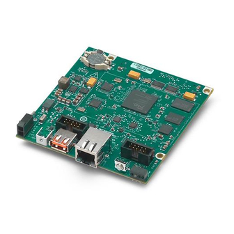
This document describes the features of the NI sbRIO-9607 and contains information about
operating the device.
sbRIO-9607
512 MB
NAND Flash
512 MB
DDR3
Status
LED
User
LED
USB
USB
Connector
PHY
ENET 0
GIGE 0
Connector
PHY
CAN Port 0
CAN
Connector
XCVR
Serial Port 1
RS-232
Connector
XCVR
FPGA
LED
Figure 1. NI sbRIO-9607 Block Diagram
Zynq-7020
Processor
FPGA
Battery
VBAT
Real-time
Clock
Reset In/Out
USB Host/Device
USB
PHY
Temp
Sensors
Pre-Magnetic MDI Pairs
GIGE 1
PHY
x96 Digital I/O (3.3 V)
x2 C Series Module Interface
40 MHz
3.3 V_Aux
Oscillator
FPGA_VIO
Optional System
Power
On-board
Power
Power
Selection
Supply
5 V
Advertisement
Table of Contents

Related Manuals for National Instruments sbRIO-9607


Summary of Contents for National Instruments sbRIO-9607
- Page 1 USER MANUAL NI sbRIO-9607 Single-Board RIO OEM Devices This document describes the features of the NI sbRIO-9607 and contains information about operating the device. Figure 1. NI sbRIO-9607 Block Diagram sbRIO-9607 Zynq-7020 512 MB Battery NAND Flash VBAT 512 MB...
-
Page 2: Table Of Contents
Powering On the NI sbRIO Device.................42 Calculating the Power Requirement................42 Configuring the sbRIO-9607....................43 Connecting the sbRIO-9607 to the Host Computer............44 Configuring Startup Options................... 45 Configuring FPGA Startup App..................46 2 | ni.com | NI sbRIO-9607 User Manual... -
Page 3: Mechanical Considerations
51.82 (2.040) 50.17 (1.975) 44.36 (1.746) USB PHY 44.38 (1.747) CPLD Pin 2 18.13 (0.714) 17.17 (0.676) 0.64 (0.025) Pin 1 Pin 2 Pin 1 1. Back of Front Panel NI sbRIO-9607 User Manual | © National Instruments | 3... - Page 4 Figure 3. Secondary-Side Dimensions in mm (in.) 4x Ø 3.18 (0.125) 1. Holes and Keepouts Sized for M3 Standoff (4.5 mm Hex) or 4-40 Standoff (3/16-in. Hex) 4 | ni.com | NI sbRIO-9607 User Manual...
-
Page 5: Maximum Component Heights
Maximum Component Heights The primary side of the sbRIO-9607 is the top side of the PCB populated with the power and Ethernet connectors. The secondary side is the bottom side of the PCB populated with the RMC connector. -
Page 6: Mounting
7.62 mm (0.300 in.) Mounting You can mount the NI sbRIO device in a variety of ways in order to maximize system performance. Some mounting methods might require custom fasteners or unique assembly 6 | ni.com | NI sbRIO-9607 User Manual... - Page 7 Mounting Direction Options The sbRIO-9607, Thermal Kit for NI sbRIO-9607/9627/9637 (153901-02), and certain RMC accessories are designed to allow traditional M-F standoff threads to pass through and stack in either direction. The following figures show possible mounting configurations and associated fastener types.
- Page 8 Mounting on a Panel or Plate with Conduction Path If possible, NI recommends that you mount the sbRIO-9607 on a panel or plate, such that a thermal solution provides a conduction path from the primary side components and is secured to or made from the panel or plate, as shown in the following figure.
- Page 9 8. Standoff, 16.00 mm (0.63 in.) 3. Heatsink 9. Standoff, 9.65 mm (0.38 in.) 4. Thermal Kit for NI sbRIO-9607/9627/9637 10. Standoff (153901-02) 11. Mounting surface 5. NI sbRIO-9607 6. RMC board NI sbRIO-9607 User Manual | © National Instruments | 9...
-
Page 10: Managing Thermal Conditions
Managing Thermal Conditions Due to the small size of the sbRIO-9607, it is very important to appropriately dissipate the heat generated during operation. You must plan for the thermal conditions of your application throughout development and validation. This section provides design recommendations and validation tools and methods for maximizing the thermal performance of the system. - Page 11 • Local ambient—The maximum air temperature as specified directly adjacent to the NI sbRIO device. This is measured on all sides of a device that has exposed circuitry. NI sbRIO-9607 User Manual | © National Instruments | 11...
-
Page 12: Validating The System
Validating Temperature Measurements Digitally To meet the thermal specifications of the sbRIO-9607, you must satisfy the requirements of either the digital or analog thermal validation approach as described in the NI sbRIO-9607 Specifications on ni.com/manuals. The sbRIO-9607 includes three onboard temperature- monitoring sensors to simplify validation of a thermal solution. - Page 13 Info Code sbriosensors Managing Power and Feature Utilization An NI sbRIO device that heavily utilizes all of its performance and features consumes and dissipates substantially more power than an idle device. NI sbRIO-9607 User Manual | © National Instruments | 13...
- Page 14 Thermal performance of the NI sbRIO device can be maximized by implementing the following recommendations. • Directly mount a thermal solution such as the Thermal Kit for NI sbRIO-9607/9627/9637 (153901-02) to a thermally conductive surface such as a metal enclosure wall or plate, as shown in the Mounting on a Panel or Plate with Conduction Path section.
- Page 15 3. Best—Vertical mounting directly to a thermally-conductive wall or plate Designing A Thermal Solution If the Thermal Kit for NI sbRIO-9607/9627/9637 (153901-02) does not satisfy your design requirements, NI recommends replicating the features of the heat spreader into your own thermal solution.
- Page 16 Figure 13. sbRIO-9607 Pedestal Dimensions in mm (in.) The following table provides the pedestal height from board surface for each corresponding component shown in the previous figure. Table 1. Pedestal Height from Board Surface Designation Pedestal Corresponding Pedestal Height from Board Surface...
-
Page 17: Shock And Vibration
If this method is not feasible for your design, minimize the amount of extra mass that only the sbRIO-9607 supports, such as a heat sink or other thermal solution, that is fastened to the four standoffs. If you require substantial thermal solutions, provide additional structural support. -
Page 18: Connector Descriptions
CLIP generator are all are routed through the FPGA. These peripherals will be temporarily unavailable when the FPGA is reconfigured. Downloading your FPGA application to the flash of the sbRIO-9607 ensures that the FPGA is configured before the driver can access a given peripheral. Refer to the... - Page 19 Table 3. Example Connector Configuration and Calculated Standoff Height Component Manufacturer, Part Number Height RMC connector Samtec SEAF-40-06.5-S-06-2-A-K- 6.50 mm (0.256 in.) Mating connector Samtec SEAM-40-03.0-S-06-2-A-K- 3.00 mm (0.118 in.) NI sbRIO-9607 User Manual | © National Instruments | 19...
-
Page 20: Power Connector
RMC. Power Connector The sbRIO-9607 has a power connector to which you can connect a power supply. The following table shows the pinout for the power connector. Table 4. Power Connector Pinout... -
Page 21: Rs-232 Serial Port
151733-10 RS-232 Serial Port The sbRIO-9607 has an RS-232 serial port that is implemented with a shrouded header, 10- position modular jack to which you can connect devices such as displays or input devices. Use the Serial VIs to read from and write to the serial port. Refer to the LabVIEW Help for information about the Serial VIs. -
Page 22: Can Port
NI Single-Board RIO 10-pin header to 9-pin D-SUB 153158-10 CAN Port The sbRIO-9607 has a CAN port that is implemented with a shrouded header, 10-position modular jack to provide connections to a CAN bus. The following figure shows the pinout for the CAN port. -
Page 23: Usb Host Ports
USB Flash drives and USB-to-IDE adapters formatted with FAT16 and FAT32 file systems. The sbRIO-9607 USB host port supports Web cameras that conform to the USB Video Device Class (UVC) protocol as well as machine vision cameras that conform to the USB3 Vision standard and are USB 2.0-compatible. -
Page 24: Reset Button
Press the RESET button to reset the processor in a similar manner as cycling power. Figure 17. RESET button 1. RESET button System Reset The following figure shows the reset behavior of the sbRIO-9607. 24 | ni.com | NI sbRIO-9607 User Manual... -
Page 25: Leds
The following table lists the POWER LED indicators. Table 11. POWER LED Indicators LED Color LED Pattern Indication Green Solid The sbRIO-9607 is powered ON. — The sbRIO-9607 is powered OFF. NI sbRIO-9607 User Manual | © National Instruments | 25... -
Page 26: Status Led Indicators
Table 12. STATUS LED Indicators LED Pattern Indication Blinks twice and The sbRIO-9607 is in safe mode. Software is not installed, which is pauses the factory default state, or software has been improperly installed on the sbRIO-9607. An error can occur when an attempt to upgrade the software is interrupted. -
Page 27: Ethernet Led Indicators
10 Mbit/s data rate selected Real-Time Clock (RTC) Battery The sbRIO-9607 contains an RTC battery, which is a lithium cell battery that stores the system clock information when the sbRIO-9607 is powered off. Only a slight drain on the RTC battery occurs when power is applied to the sbRIO-9607 power connector. -
Page 28: Internal Real-Time Clock (Rtc)
NI sbRIO device. Figure 20. RMC Connector Location and Dimensions on Example RMC Pin 1 98.40 (3.000) 96.75 (3.809) 0.0 (0.000) 0.0 (0.000) Caution RMCs are not hot-swappable. Disconnect power before mating or unmating. 28 | ni.com | NI sbRIO-9607 User Manual... -
Page 29: Rmc Connector Pins
The pins on the RMC connector are divided into the following groups: • Pins with dedicated functions. • General purpose digital I/O pins. • Pins reserved for future use. Note Leave reserved and unused pins disconnected on RMCs. NI sbRIO-9607 User Manual | © National Instruments | 29... - Page 30 RTC on the host system. The RTC will track absolute VBAT — time as long as either the main system battery or RMC battery through VBAT pin contains sufficient charge. 30 | ni.com | NI sbRIO-9607 User Manual...
- Page 31 RMC connector host system has been reset. Resets System reset used to reset the RMC connector host system. SYS_RST# LVTTL 3.3V Asserting this pin causes the RST# pin to also assert. NI sbRIO-9607 User Manual | © National Instruments | 31...
- Page 32 — Host. Connect to +3.3V to configure (after the USB port as Device. PHY) USB_CPEN Refer to the sbRIO-9607/9627 LVTTL 3.3V RMC Design Guide for more information about these USB_VBUS — signals. 32 | ni.com | NI sbRIO-9607 User Manual...
-
Page 33: Rmc Connector Pin Listing By Location
I/O pins SDHC peripherals on an RMC. RMC Connector Pin Listing by Location The following table lists the pinout for the RMC connector and indicates the pin number and corresponding function. NI sbRIO-9607 User Manual | © National Instruments | 33... - Page 34 236 - VBAT 237 - GND 238 - RESERVED 239 - FPGA_CONF 240 - FPGA_VIO Power Differential IO Reserved Singled Ended IO Routed to FPGA Global Clock Resources on the Host System 34 | ni.com | NI sbRIO-9607 User Manual...
- Page 35 Pin 42 - RESERVED of the RMC connector provides 3.3 V to the RMC in order to maintain compatibility with the sbRIO-9605/06/23/26 RMC pinout. This pin is not recommended for use with new designs. NI sbRIO-9607 User Manual | © National Instruments | 35...
-
Page 36: Rmc Connector Power Requirements
5 V and FPGA_VIO coming up in any order. RMC Connector Electrical Characteristics Each pin in an RMC connector conforms to a particular I/O standard. On the sbRIO-9607, the LVTTL I/O standard meets the input and output logic levels defined in the NI sbRIO-9607 3.3V... -
Page 37: Vin_Filtered
4.2 μA average USB Support The USB interface supports both host mode and device mode USB. The USB pairs connect to either a USB connector or to a USB device on the RMC board. The NI sbRIO-9607/9627 RMC Design Guide on ni.com/manuals provides design guidelines, requirements for routing signals, and recommendations for an appropriate connector. -
Page 38: Rmc Ethernet Support
The C Series DIO lines provides up to two slots of C Series support on the RMC. All lines can be connected directly to the 15-pin DSUB connector except for the 5 V power. The 5 V power 38 | ni.com | NI sbRIO-9607 User Manual... -
Page 39: Rmc Rst
The RST# pin indicates that power provided through the RMC Connector is valid or that the sbRIO-9607 is in reset. The signal goes to 3.3 V if the power is valid when the board powers up or when coming out of reset. The signal asserts to 0 V for at least 1 ms before returning to 3.3 V when going into reset. - Page 40 NI sbRIO device are routed with a 55 Ω characteristic trace impedance. Route all RMCs with a similar impedance to ensure the best signal quality. Refer to 3.3 V Digital I/O on RMC Connector section in the NI sbRIO-9607 Specifications on ni.com/manuals for the logic levels.
-
Page 41: Power Requirements
NI sbRIO-9607/9627 RMC Design Guide on ni.com/manuals provides design guidelines, requirements for routing signals, requirements for pull-up resistors, and recommendations for an appropriate connector. Refer to SD Card Slot in the NI sbRIO-9607 Specifications on ni.com/manuals for the specifications. Power Requirements The NI sbRIO device requires a 9 VDC to 30 VDC external power supply. -
Page 42: Powering On The Ni Sbrio Device
3.3 V voltage output across the RMC connector 3.3V is the power consumption of a device plugged into the USB port When calculating each component of the maximum power consumption the following efficiency factors must be used: 42 | ni.com | NI sbRIO-9607 User Manual... -
Page 43: Configuring The Sbrio-9607
Configuring the sbRIO-9607 You can connect the sbRIO-9607 to a host computer or network and configure the startup options using the RJ-45 Gigabit Ethernet port. If a RIO Mezzanine Card is designed with a device USB connector, the target can also be configured using the device USB port. -
Page 44: Connecting The Sbrio-9607 To The Host Computer
NI-sbRIO-9607-########. Finding the sbRIO-9607 on the Network (Static IP) Complete the following steps to find the sbRIO-9607 on the network if the host computer is using a static IP address. The following instructions are for host computers running Microsoft Windows 7. -
Page 45: Configuring Startup Options
Click Properties. Record the IP address, Subnet mask, and Default gateway address. You need these settings to configure the network settings of the sbRIO-9607 and to restore the network settings of the host computer. You can also access these settings by opening the Start menu,... -
Page 46: Configuring Fpga Startup App
Table 23. sbRIO-9607 Startup Options Startup Option Description Force Safe Mode Rebooting the sbRIO-9607 with this setting on starts the sbRIO-9607 without launching LabVIEW Real-Time or any startup applications. In safe mode, the sbRIO-9607 launches only the services necessary for updating configuration and installing software. -
Page 47: Connecting Can Networks
Connecting CAN Networks The sbRIO-9607 is populated with one IDC header to provide connections to a CAN bus. This connector has pins for CAN_H and CAN_L, which can connect to the CAN bus signals. The CAN port uses an NXP PCA82C251T high-speed CAN transceiver that is fully compatible with the ISO 11898 standard and supports baud rates up to 1 Mbps. -
Page 48: Termination Resistors
I/O operations with the specific drive finish before removing the device. Refer to the LabVIEW Help for more information. The file system of the sbRIO-9607 follows conventions established for UNIX-style operating systems. Other LabVIEW Real-Time targets follow Microsoft Windows-style conventions. In... -
Page 49: Worldwide Support And Services
For example, it is possible to link , where /C/ni-rt/system dynamic libraries are deployed on other LabVIEW Real-Time targets, to /usr/local/lib where they are stored on the sbRIO-9607, if the application requires this. For more information, visit ni.com/info and enter the Info Code RT_Paths Worldwide Support and Services The National Instruments website is your complete resource for technical support. - Page 50 Other product and company names mentioned herein are trademarks or trade names of their respective companies. For patents covering National Instruments products/technology, refer to the appropriate location: Help»Patents in your software, the file on your media, or the National Instruments Patent Notice at .
Need help?
Do you have a question about the sbRIO-9607 and is the answer not in the manual?
Questions and answers