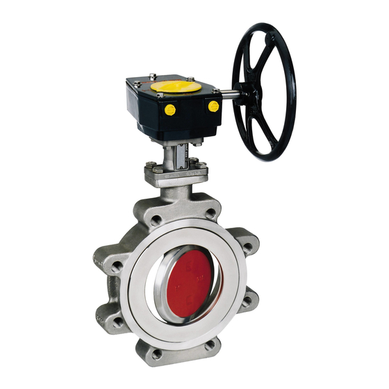
Table of Contents
Advertisement
Operating Instructions
8450.810/15--EN
1.
Declaration of conformity
2.
Declaration of incorporation for Partly Completed machinery
3.
General
4.
Safety
5.
Transport and interim storage
6.
Description of valves
7.
Installation
8.
Commissioning / Decommissionning
9.
Maintenance / Repair
10. Trouble shooting
DANAÏS 150
DANAÏS MT II
DANAÏS TBT II
DANAÏS TBT AL
2
4
5
5
6
7
10
15
15
16
42 048 660
Advertisement
Table of Contents

Summary of Contents for KSB DANAIS 150
- Page 1 Operating Instructions 8450.810/15--EN DANAÏS 150 DANAÏS MT II DANAÏS TBT II DANAÏS TBT AL Declaration of conformity Declaration of incorporation for Partly Completed machinery General Safety Transport and interim storage Description of valves Installation Commissioning / Decommissionning Maintenance / Repair 10.
-
Page 2: Declaration Of Conformity
- - with the requirements of the Pressure Equipment Directive 2014/68/EU. Description of the valve types: Butterfly valves -- DANAIS 150 Class 150 DN 50 (2”) --1200 (48”) (PS maximum 20 bar) PN 25 DN 50 (2”) --1200 (48”) - Page 3 S with the requirements of the regulation EC REACH 1907/2006. Regulation EC 1907/2006 on the registration, evaluation, authorization and restrictions of chemicals Description of the valve types: Butterfly valves -- DANAIS MT II Class 150 DN 50--1000 PN 25 DN 50--600 Class 300 DN 50--600 -- DANAÏS 150...
- Page 4 This documentation of parts hereof will be transmitted by post or electronically in response to a reasoned request by the national authorities. The person authorised to compile the relevant thecnical documentation by: Jacques Peterschmitt - - KSB Parc d’activité Rémora...
- Page 5 Safety instructions put forth in this instruction manual, the nonobservance of which would involve the risk of personal injury, they Design, manufacturing and testing of the KSB valves are subject to a are specially marked with the general hazard symbol: Quality Assurance System according to EN ISO 9001 and to the European Pressure Equipment Directive 2014/68/EU (PED).
-
Page 6: Transport And Interim Storage
4.6. Safety lnstructions for Maintenance, Inspection and Installation work 4.6.1. General On an actuated valve the operating instructions of the valve must be strictly followed as well as those of the operating instructions of the actuators, the limit switch or automation boxes. The user is responsible for ensuring that all maintenance, inspection and installation work is carried out by authorized, adequately qualified staff who are thoroughly familiar with thisinstruction manual. - Page 7 Description of valves Class 150 DN 50 - - 250 The sectional drawings shown hereafter are examples for the general Class 300 DN 50 - - 200 design of our valves. For drawings and other information pertaining to a specific valve series, please refer to the relevant type leaflets and specific technical drawings.
- Page 8 Type Size (mm) Type series booklet no. DANAÏS 150 - - SEATS DANAÏS 150 50 -- 1200 8460.11 DN 50 - - 650 DN 50- - 600 144.1 72--3 Plastomer seat 01--48 Plastomer seat 144.2 901.1 fire safe 144.1 310.1 144.1 72--3 72--3...
-
Page 9: List Of Components
6.3. List of Components Type DN (mm) Type series booklet no. DANAÏS TBT II (Flanged 80 -- 1200 8460.1241 and Buttweld) Part No. Name of Parts 01--48 Fire--safe sealing packing Examples with Buttweld ends: 13--21 Extension 41--2 Static ring 561.1 Detail A 50--5 Reaction ring... -
Page 10: Installation Conditions
6.4. Functioning principle Description lf a valve is used as end-valve in a pipe, this valve should be protected against unauthorized or unintentional opening to prevent The valve consists mainly of a body (100), operating shaft (213), shaft personal injury or damage to property. (210), disc (550) and different types of seats (144). - Page 11 Wafer and Lug type class 300 7.2.2. Flanging dimensions Connection to the piping. Disc clearance Size Size Piping flanges must match the following dimensions. 2 ½ Flanged type class 300 Disc clearance Size Size 50--65 2--2 ½ e1: min. allowable diameter on uspstream flange face e3: min.
- Page 12 7.2.3.2. DANAÏS TBT II, DIMENSIONS OF GASKET FOR 7.2.3. Flange gasket FLANGED BODY (T7) The dimensional compatibily of the flange gasket must be checked to ensure the connection quality, according to the dimensions defined hereunder: To ensure proper connection the dimensions of flange gaskets must be compatible with the dimensions specified below: 7.2.3.1.
- Page 13 7.2.3.3. DANAÏS 150 GASKET DIMENSIONS Lug type body Wafer type body Flange sealing Connections Min. area Max. area Max. Min. Max. external dia. Wafer type -- T1 Wafer type Full Lug type body -- T3/T4 Full Lug type body T3/T4 internal internal ext.
-
Page 14: Recommendations For Installation
For valves with lifting lugs, please use only load rings provided side by KSB for handling the valve from the box to the pipe. Load rings must be fully screwed (until it stops). BWSE (Butt- -welded connection type) Horizontal It is forbidden to handle the aggregate only by the actuator. -
Page 15: Maintenance & Repair
All components are specific, so after valve draining, it is mandatory to use the same special screw and only spare parts provided by KSB Cryogenic type BW: special device like “bracket” used for the (like described in the manual of maintenance). -
Page 16: Troubleshooting General
Check type and flange bolting torque Wrong flanging size Follow instructions given in KSB technical leaflet Wrong face to face, Flanging has to be modified in accordance with KSB technical leaflet non parallel flanges requirements. Flow conditions Check the technical offer versus service conditions...


Need help?
Do you have a question about the DANAIS 150 and is the answer not in the manual?
Questions and answers