
Related Manuals for BLU-JET LEGACY


Summary of Contents for BLU-JET LEGACY
- Page 1 LEGACY Assembly and Operators Manual Manual Number 0605010 Rev. 2-19-18 $20.00 Net.
- Page 2 1708 H Ave • Box 218 • Thurston, Nebraska, 68062-0218 Phone: 402-385-3041 • E-mail: box218@thurstonmfgco.com Design specifications and features as described are subject to change without notice. BLU-JET is a registered trademark of Thurston Manufacturing Company, Thurston NE. /SIronWorks @SIronWorks...
- Page 3 Meter Assembly GDI200A With Dual Impellicone Manifold, (66000129) 15 Row 30 LEGACY 66000129 NOTE: GENERIC EXPLODED VIEW. CONSULT BOTTOM MANIFOLD DIAGRAM FOR HOSE BARB AND PLUG PLACEMENT. Extend to Knives Extend to Gauge From Meter...
-
Page 4: Table Of Contents
Secondary Wing Stop and Straight Extension------------------------------------------------------------ Secondary Wing Extension To 50 ft.-------------------------------------------------------------------------- 43 Pin Adjust Gauge Wheel---------------------------------------------------------------------------------------- 44 Decals--------------------------------------------------------------------------------------------------------------- 45 Legacy 38’, 42’, 47’, 52’ Toolbars----------------------------------------------------------------------------- 46 Legacy Hydraulics 38’, 42’, And 47’--------------------------------------------------------------------------- 48 Hose Kit 38’, 42’, And 47’---------------------------------------------------------------------------------------- 52 Legacy Hydraulics 52’-------------------------------------------------------------------------------------------- 54 Hose Kit 52’--------------------------------------------------------------------------------------------------------- 57... - Page 5 Environmental, Safety, Quality, Production and Engineering keep our firm at the cutting edge of technology. We hope your BLU-JET equipment will give you years of service. ead this manual carefully. It will instruct you on how to operate and service your machine safely and correctly. Failure to do so could result in personal injury and/or equipment damage.
-
Page 6: Introduction
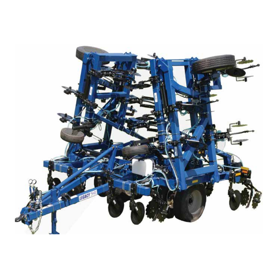
The BLU-JET Legacy Commercial Class Fertilizer Injection Applicator achieves a new performance dimension for high acre, high rate applications. The BLU-JET Legacy can easily be configured for a number of operations including Pre-Plant, Side-Dress, and StripTill applications with anhydrous, liquid, dry, or dual placement fertilizer injection. -
Page 7: Deliver
Dealer Checklist LEGACY o The Dealer: Inspect the implement thoroughly after assembly to be certain it is functioning properly before delivering it to the customer. The following checklist is a reminder of points to cover. Check off each item as it is found satisfactory or after proper adjustment is made. -
Page 8: To The Owner
To The Owner LEGACY hank you for your recent purchase of a new BLU-JET implement. The primary objective of Thurston Manufacturing Company is to build and provide you with a quality product. However, in the event that a problem does occur, it is imperative that your warranty registration is on file in order to accurately respond to your specific service circumstances. -
Page 9: Warranty
Warranty begins from date of delivery to the original purchaser and applies to all new BLU-JET products that have not been altered and are being used for the intended purpose. Negligence, abuse or modification of equipment manufactured by or purchased and resold by Thurston Manufacturing Company will void this warranty. -
Page 10: Safety
Safety LEGACY RECOGNIZE SAFETY INFORMATION • This is the safety-alert symbol. When you see his symbol on your machine or in this manual, be alert to the potential for personal injury. Follow recommended precautions and safe operating practices. FOLLOW SAFETY INSTRUCTIONS •... - Page 11 Safety LEGACY HIGHWAY AND TRANSPORT OPERATIONS • Plan your route to avoid heavy traffic. • Be a safe and courteous driver. Always yield to oncoming traffic in all situations, including narrow bridges, intersection, etc. • Be observant of bridge loading ratings. Do not cross bridges rated lower than the gross weight at which you are operating.
- Page 12 Safety LEGACY Observe Safety Signs AP 2234-7-98 AP 2222 8-90 AP 2469-7-98 AP 2483-8-98 AP 2914...
- Page 13 Safety Decals LEGACY AP 2972 AP 2227 AP 2973 AP 2975 AP 2974...
-
Page 14: Operating Instructions
Operating Instructions LEGACY Hitch 1. The tractor must be equipped with a drawbar and a draw- bar safety chain clevis. For rigid frame tractors equipped with swinging drawbar, the NOTE: drawbar must be located in a Implement fixed position in the center of hitch weights the tractor. - Page 15 Operating Instructions LEGACY Remote 5. Connect the toolbar hydraulic hoses to the tractor remote hydraulic couplers. The 1/2” hoses NOTE: supply oil to the toolbar lift Always cylinders. The 3/8” hoses connect the supply oil to the wing fold hoses so cylinders.
- Page 16 Operating Instructions LEGACY 9. Before leveling the machine Leveling the tire pressure should be Machine checked. Inflate center section lugged tractor tires to 51 P.S.I. Maximum Truck tires 95 P.S.I. Maximum Before beginning operation of this machine the main frame must be level.
- Page 17 Operating Instructions LEGACY Tighten one inch Leveling 11. Check tire pressure before hex nuts after adjustable adjusting. wheel adjustment. Loosen the two 1” x 4” Hex bolts gauge at the top of the adjust linkage. wheels Loosen 1” hex nut on inside of NOTE: threaded rod.
- Page 18 Operating Instructions LEGACY LOCKED POSTION DEPTH ADJUSTMENT One complete revolution equals 1/2” of depth increase. LOCKING DEPTH ADJUSTMENT LINKAGE Rotate depth control adjuster latch over handle and lock in place with (27) (BP3376) 1/4” x 2” wire retaining pin.
- Page 19 Operating Instructions LEGACY Nurse tank 14. Nurse tank hitch can be retracted and moved from hitch side to side for easy hookup. NOTE: Hitch will automatically lock Periodically in the extended position. check Latch mechanism to WARNING ensure proper Pinch point...
- Page 20 Operating Instructions LEGACY 18. Lubrication Lug Nut 17. Lug nut Torque 1. Check every hour first four • Torque Grease all zerks daily hours. • Grease coulters daily 2. Check every four hours to first twenty hours. 3. Check once every fifty hours Lift Wheel Pivot Zerk thereafter.
- Page 21 Operating Instructions LEGACY Lubrication Zerks On Linkage And Hinge Zerks On Wing Gauge Wheel Pivot (Torque 100 ft./lbs.) Zerks On Linkage And Hinge Zerks On Linkage And Hinge 19. Grease all coulter arm pivots. Coulter pivot shaft lubrication Coulter 20. The plug on the coulter hub can be removed.
-
Page 22: Anhydrous Ammonia Operating Instructions
Anhydrous Ammonia Operating Instructions LEGACY Attend Anhydrous Ammonia Safety Training Class Provided By Your Dealer Before Operating this equipment . Operator protection Because of the hazards associated with handling Anhydrous Ammonia, operators must use proper protective equipment. Minimum equipment includes... - Page 23 Anhydrous Ammonia Operating Instructions LEGACY Disconnection Of Nurse Tank 1. With personal protective equipment in place, and beginning at the tank, fully shut off the supply hose valves. If the supply hose is a tank wagon component (as opposed to a tool bar component) an additional hand operated globe valve shut off located between the quick coupler and the Heat Exchanger feed line will significantly speed up the tank wagon change process.
- Page 24 Safety Decals LEGACY AP2972 AP2227 AP2973 AP2975 AP2974...
-
Page 25: Coupler Operation
Coupler Operations LEGACY NOTE: Coupler release handle Read coupler Female coupler operation Male coupler neck decal (AP2974) Body Guard III for safety Flow Feed-line to tank instructions. Downstream Coupler bleed valve Male coupler half Check valve plunger Connecting 1. Stand on the upwind side. Close all feed-line valves and inspect all components for proper condition. -
Page 26: Emergency Fresh Water Tank
BP3158 WASHER, LOCK, 5/16”, PLATED BP3108 HEX CAP SCREW, 5/16”-18 X 1, GRADE 5, PLATED BP3002 WASHER, LOCK, 3/8”, PLATED BP3001 NUT, HEX, 3/8”-16, GRADE 2, PLATED BP3351 U-BOLT, 3/8”-16 X 6”W X 7”L AP2215 DECAL, BLU-JET, 3” X 8”... -
Page 27: Main Frame
Center Section Area of Bundle 66000126 LEGACY BOM ID Item No Description 66000126 LEGACY MAIN FRAME & PRIMARY WINGS AAM2437 HOSE RETAINER ASSEMBLY, CLOSED LOOP, 4X6 TUBE AM4015 HOSE RETAINER, CLOSED LOOP, 6” & 7” MOUNTING BP3001 NUT, HEX, 3/8”-16, GRADE 2, PLATED BP3002 WASHER, LOCK, 3/8”, PLATED... - Page 28 ARM, VALVE, DEPTH CONTROL AM6266 LINKAGE, STOP, DEPTH CONTROL AM6271 LATCH, DEPTH CONTROL ADJUSTER AM6276 ADJUSTER BRACKET, LEGACY DEPTH CONTROL AP2215 DECAL, BLU-JET, 3” X 8” AP2222 DECAL, STAND CLEAR OF TONGUE, TONGUE LIGHT AP2231 DECAL, FEMA, 2-1/2” X 1-1/2”...
- Page 29 Center Section Area of Bundle 66000126 LEGACY BP3015 WASHER, FLAT, 3/8”, PLATED BP3019 NUT, HEX, 1”-8, GRADE 2, PLATED BP3020 WASHER, LOCK, 1, PLATED BP3027 NUT, HEX LOCK, 3/4”-10, GRADE 2, PLATED BP3034 NUT, HEX, 3/4”-10, GRD 2, PLATED BP3035 WASHER, LOCK, 3/4”, PLATED...
- Page 30 Center Section Area of Bundle 66000126 LEGACY BOM ID Item No Description AM4015 HOSE RETAINER, CLOSED LOOP, 6” & 7” MOUNTING AM6172 FRAME, MAIN, AT6020 BP3516 TENSION BUSHING, 1-1/4” X 1” X 1” OAL AM6179 LINKAGE, CYLINDER LUG SUPPORT AM6182...
- Page 31 Center Section Area of Bundle 66000126 LEGACY BOM ID Item No Description AAM2437 HOSE RETAINER ASSEMBLY, CLOSED LOOP, 4X6 TUBE AM4015 HOSE RETAINER, CLOSED LOOP, 6” & 7” MOUNTING BP3001 NUT, HEX, 3/8”-16, GRADE 2, PLATED BP3002 WASHER, LOCK, 3/8”, PLATED BP3045 U-BOLT, 3/8”-16 X 6”W X 5”L, PLATED...
- Page 32 DECAL, STAND CLEAR OF TONGUE, TONGUE LIGHT AP2231 DECAL, FEMA, 2-1/2” X 1-1/2” AP2469 DECAL, SAFETY CHAIN AP2483 DECAL, DANGER, FALLING FROM EQUIPMENT AP2554 DECAL, LEGACY AP2711 SNAP RING, 1-1/4” EXTERNAL, HEAVY DUTY AP2864 PERFECT HITCH, CAT IV, BLACK AP2871 HOSE RETAINER AP2914...
- Page 33 Center Section Area of Bundle 66000126 Depth Control Assembly LEGACY...
- Page 34 Depth Control Assembly LEGACY BOM ID Item No Description AAM2928 STOP ARM, W/ PLUNGER, DEPTH CONTROL AAM2930 ADJUSTMENT LINKAGE, LEGACY DEPTH CONTROL AM6263 BRACKET, PIVOT, DEPTH CONTROL AM6264 ARM, VALVE, DEPTH CONTROL AM6266 LINKAGE, STOP, DEPTH CONTROL AM6271 LATCH, DEPTH CONTROL ADJUSTER...
-
Page 35: Primary Wing Right-Hand
Primary Wing Right-hand Area of Bundle 66000126 LEGACY Tractor Side Tractor Side AAM2800 AAM2800-1 AM 4597 NOTE: NOTE: AAM2800 (With tapered wheel nuts) AAM2800-1 (With flange lock nuts) and 295/75R22.5 gauge wheel tires. AM4597 hub cap strap are used only with Do not use AM 4597 with tapered wheel nuts. - Page 36 TENSION BUSHING, 1-1/4” X 1” X 1” OAL BP3538 TENSION BUSHING, 2” X 1-3/4” X 1-1/2” OAL AM6188 WING, PRIMARY, RH, AT6010 AP2215 DECAL, BLU-JET, 3” X 8” AP2234 DECAL, DANGER STAND CLEAR FALLING WING AP2711 SNAP RING, 1-1/4” EXTERNAL, HEAVY DUTY BM3485 PIN, 1-3/4”...
-
Page 37: Primary Wing Left-Hand
Primary Wing Left-hand Area of Bundle 66000126 LEGACY AAM2800 AAM2800-1 AM 4597 NOTE: NOTE: AAM2800 (With tapered wheel nuts) AAM2800-1 (With flange lock nuts) and 295/75R22.5 gauge wheel tires. AM4597 hub cap strap are used only with Do not use AM 4597 with tapered wheel nuts. - Page 38 TENSION BUSHING, 1-1/4” X 1” X 1” OAL BP3538 TENSION BUSHING, 2” X 1-3/4” X 1-1/2” OAL AM6187 WING, PRIMARY, LH, AT6010 AP2215 DECAL, BLU-JET, 3” X 8” AP2234 DECAL, DANGER STAND CLEAR FALLING WING AP2711 SNAP RING, 1-1/4” EXTERNAL, HEAVY DUTY BM3485 PIN, 1-3/4”...
- Page 39 Secondary Wing Economy Right Side Bundle 66000106 LEGACY Part of Bundle Number: 66000106 SECONDARY WING ECONOMY RIGHT SIDE Tractor Side Tractor Side...
- Page 40 MACHINERY BUSHING, 1-1/2” OD X 1” ID, 14 GAUGE, PLATED BP3350 U-BOLT, 3/4”-10 X 6”W X 7-11/16”L, PLATED BP3511 PIN, COTTER, 3/16” X 1-3/4” AM4552 WING, SECONDARY, 5’8”, RIGHT-HAND, LEGACY AM4565 SECONDARY WING REST AM6189 LINKAGE, SECONDARY FOLD, AT6010 BP3072 GREASE ZERK, 1/4”-28...
- Page 41 Secondary Wing Economy Left Side Bundle 66000106 LEGACY PART OF BUNDLE NUMBER: 66000106 SECONDARY WING ECONOMY LEFT SIDE Tractor Side Tractor Side...
- Page 42 MACHINERY BUSHING, 1-1/2” OD X 1” ID, 14 GAUGE, PLATED BP3350 U-BOLT, 3/4”-10 X 6”W X 7-11/16”L, PLATED BP3511 PIN, COTTER, 3/16” X 1-3/4” AM4551 WING, SECONDARY, 5’8”, LEFT-HAND, LEGACY AM4565 SECONDARY WING REST AM6189 LINKAGE, SECONDARY FOLD, AT6010 BP3072 GREASE ZERK, 1/4”-28...
- Page 43 Secondary Wing, 3’-2” Right Side Bundle 66000128 LEGACY BUNDLE NUMBER: 66000128 SECONDARY WING 3’-2” RIGHT SIDE Tractor Side BUNDLE: 66000128 LEGACY, SECONDARY WINGS, 3’-2” RIGHT SIDE BOM ID Item No Description AM4565 SECONDARY WING REST AM6189 LINKAGE, SECONDARY FOLD, AT6010 BP3072 GREASE ZERK, 1/4”-28...
- Page 44 Secondary Wing, 3’-2” Left Side Bundle 66000128 LEGACY Bundle Number: 66000128 SECONDARY WING 3’-2” LEFT SIDE Tractor Side BUNDLE: 66000128 LEGACY, SECONDARY WINGS, 3’-2” LEFT SIDE BOM ID Item No Description AM4565 SECONDARY WING REST AM6189 LINKAGE, SECONDARY FOLD, AT6010 BP3072 GREASE ZERK, 1/4”-28...
-
Page 45: Dual Wheel Lift
Bundle: 66000127 Legacy Dual Wheel Lift 385/65R22.5 Tires LEGACY Valve Stems to the Inside Valve Stems to the Inside BUNDLE: 66000127 LEGACY DUAL WHEEL LIFT, 385/65R22.5 TIRES BOM ID Item No Description AAM2924 WHEEL, 385/65 R22.5, 22.5 X 11.75 X 8, GRAY... - Page 46 Bundle: 66000124 AT6020 Dual Wheel Lift 295/75R22.5 Tires LEGACY Valve Stems to the Outside Valve Stems to the Outside BUNDLE: 66000124 LEGACY DUAL WHEEL LIFT, 295/75R22.5 TIRES BOM ID Item No Description AAM2923 WHEEL, 295/75R22.5, 22.5 X 8.25 X 8, GRAY, RECAP AP3216 RIM, 22.5 X 8.25 X 8, -1-1/2”...
-
Page 47: Single Wheel Lift
Single Wheel Lift Parts Bundle 66000104 LEGACY Bundle Number: 66000104 (LEGACY SINGLE WHEEL) NOTE: Valve stem on each wheel is positioned to the inside on 30”, 15” and 20”. - Page 48 Single Wheel Lift Parts Bundle 66000104 LEGACY PART OF 66000104 (LEGACY SINGLE WHEEL LIFT) BOM ID Qty Item No Description AAM2788-1 ASSEMBLY, HUB AND SPINDLE, 758 HUB, 3 X 16 WITH LOCK AM6226 WHEEL LEG, SINGLE WHEEL, LEFT-HAND BP3213 GREASE ZERK BP3516 TENSION BUSHING, 1-1/4”...
-
Page 49: Secondary Wing Stop And Straight Extension
Secondary Wing Stop and Straight Extension LEGACY Part of Bundle Number: 66000106 (SECONDARY WINGS) BOM ID Item No Description AM4551 WING, SECONDARY, 5’8”, LEFT-HAND, LEGACY AM4565 SECONDARY WING REST BP3034 NUT, HEX, 3/4”-10, GRADE 2, PLATED BP3035 WASHER, LOCK, 3/4”, PLATED BP3139 HEX CAP SCREW, 3/4”-10 X 2”, GRADE 5, PLATED... -
Page 50: Secondary Wing Extension To 50 Ft
Bundle: 66000125 Secondary Wing Extension To 50 Ft. LEGACY BUNDLE: 66000125 SECONDARY WING EXTENSION TO 50 FT. BOM ID Item No Description AM4547 BRACKET, SPACER, 13-1/2” OAL AM6189 LINKAGE, SECONDARY FOLD, AT6010 BP3072 GREASE ZERK, 1/4”-28 AM6197 WING LINKAGE, 12-1/4”, W/ 1-1/4” HOLE BP3072 GREASE ZERK, 1/4”-28... -
Page 51: Pin Adjust Gauge Wheel
Gauge Wheel With Pin Adjust & 25 x 7.50 x 15 Tire & Rim LEGACY Part of Bundle Number: 66000106 BUNDLE NUMBER 55000100 (PIN ADJUST GAUGE WHEEL) Tractor side of tool bar 55000100 GAUGE WHEEL, PIN ADJUST 6” X 6” MOUNTING, 25-750-6-6 1 PAIR... - Page 52 AP 2231 Decal, FEMA, 2-1/2” x 1-1/2” AP 2234 Decal, Danger stand clear falling wing AP 2469 Decal, Safety Chain AP 2483 Decal, Danger, falling from equipment AP 2914 Decal, Warning, high pressure fluid AP 2554 Decal, LEGACY 4.75” x 20.75”...
-
Page 53: Legacy 38', 42', 47', 52' Toolbars
Legacy 38’ and 42’, Toolbars, LEGACY Legacy 38’ Legacy 42’ Legacy SD 42’... - Page 54 Legacy 47’ and 52’ Toolbars, LEGACY Legacy 47’ Legacy 52’...
- Page 55 PKG00205 Base, Up to 48’ LEGACY Tractor side BOM ID Qty Item No Description PKG00205 PACKAGE, HYD, LEGACY BASE, UPTO 45’ AM2090 BRACKET, DEPTH COLLAR & LOCKUP STORAGE AM6159 BRACKET, MOUNTING, FLOW DIVIDER VALVE AM6280 TRANSPORT CYLINDER LOCK, 1-3/4” & 2” CYL ROD, 12”...
- Page 56 Legacy Hydraulic Package PKG00205 Base, Up to 48’ LEGACY Tractor side Tractor side...
- Page 57 Legacy Hydraulic Package PKG00205 Base, Up to 48’ LEGACY Left-hand from the rear Tractor side Right-hand from the rear Tractor side...
-
Page 58: Legacy Hydraulics 38', 42', And 47
Legacy 38’, 42’, 47’ Hydraulics LEGACY BOM ID Item No Description DP4496 HOSE, HYD, 1/2 X 114, 10FJX-10FJX DP5001 HOSE, HYD, 1/2 X 168, 10FJX-10FJX DP5230 HOSE, HYD, 1/2 X 42, 10FJX-10FJX DP5184 HOSE, HYD, 1/2 X 192, 10FJX-10FJX DP5186... - Page 59 Legacy 38’, 42’, 47’ Hydraulics LEGACY...
- Page 60 Legacy 38’, 42’, 47’ Hydraulics LEGACY Legacy 42’ Legacy 42’...
-
Page 61: Legacy Hydraulics 52
Legacy Hydraulics 52’ LEGACY... - Page 62 Hydraulics from 66000125, AT6020, Secondary Wing Extensions To 50’ BOM ID Qty Item No Description PKG00205 PACKAGE, HYD, LEGACY BASE, UPTO 45’ AM2090 BRACKET, DEPTH COLLAR & LOCKUP STORAGE AM6159 BRACKET, MOUNTING, FLOW DIVIDER VALVE AM6280 TRANSPORT CYLINDER LOCK, 1-3/4” & 2” CYL ROD, 12”...
- Page 63 Legacy 52’ Hydraulics LEGACY Tractor side Tractor side...
- Page 64 Legacy 52’ Hydraulic Hoses LEGACY Includes: PKG000205 Package, Hydraulic, AT6020 Base, Up To 45’ Economy Hydraulics from 66000106, AT6020, Secondary Wings Economy Hydraulics from 66000125, AT6020, Secondary Wing Extensions To 50’ Right-hand from the rear BOM ID Item No Description DP4496 HOSE, HYDRAULIC, 1/2”...
- Page 65 Legacy 52’ Hydraulics LEGACY...
- Page 66 Legacy 52’ Hydraulics LEGACY...
-
Page 67: Stagger Brackets Offset 6 X 6 Mounting
Stagger Brackets Offset 6” x 6” Mounting LEGACY BOM ID Item No Description AAM2141 BRACKET, OFFSET STAGGER, 22 X 8, 6 X 6, W/ HARDWARE AM4510 BRACKET, OFFSET STAGGER, 22 X 8 BP3350 U-BOLT, 3/4”-10 X 6”W X 7-11/16”L, PLATED BP3034 NUT, HEX, 3/4”-10, GRADE 2, PLATED... - Page 68 Stagger Brackets Offset 6” x 6” Mounting LEGACY NOTE: Consult row spacing diagram for placement of offset stagger brackets. BOM ID Qty Item No Description AAM2122 BRACKET, OFFSET STAGGER, 33 X 20, 6 X 6, W/HARDWARE AM4509 BRACKET, OFFSET STAGGER, 33X20 BP3034 NUT, HEX, 3/4”-10 GRADE 2, PLATED...
- Page 69 CASTING, COULTER KNEE, MACHINED AM2796 SPRING CAP & GUIDE, HD COULTER AM2797 COULTER ARM, HD AP2216 DECAL, BLU-JET, SMALL, 1-1/2” X 4” AP2029 PIN, COTTER, 5/32” X 1-1/2” AP2704 NUT, SPINDLE, 3/4”-16 AP2705 WASHER, SPINDLE, 1-1/2” X 13/16” X .134”...
- Page 70 PKG00234 Nurse Tank Hitch Assembly Parts LEGACY BOM ID Item No Description PKG00234 NURSE TANK HITCH ASSEMBLY, AT6020 AAM2931 ASSEMBLY, NURSE TANK HITCH, AUTO-LOK, W/O PIN AM6220 BRACKET, HITCH MOUNTING, AT6010 NURSE TANK AM6273 BRACKET, NURSE TANK HITCH MOUNTING, LOW AM6278 LINKAGE, NURSE TANK HITCH, 12-3/4”...
- Page 71 PKG00247 Nurse Tank Hitch Assembly, Low Mounting Parts LEGACY BOM ID Item No Description PKG00247 NURSE TANK HITCH ASSEMBLY, AT6, LOW MOUNTING AAM2931 ASSEMBLY, NURSE TANK HITCH, AUTO-LOK, W/O PIN AM6234 BRACKET, LOW HITCH MOUNTING, AT6020 NURSE TANK AM6273 BRACKET, NURSE TANK HITCH MOUNTING, LOW AM6278 LINKAGE, NURSE TANK HITCH, 12-3/4”...
- Page 72 Auto-Lok Nurse Tank Hitch AAM2931 Parts LEGACY BOM ID Item No Description AAM2931 ASSEMBLY, NURSE TANK HITCH, AUTO-LOK, W/O PIN AM4533 HITCH, SWING SLIDE INSERT, STANDARD AM4534 FLIPPER HITCH, STANDARD, NURSE TANK HITCH AM4539 SAFETY LATCH AM4540 BACKING PLATE, SAFETY CHAIN LOOP, STD NURSE TANK HITCH...
-
Page 73: Blades
Blades LEGACY Coulter Blade Fluted Blade 20” AP2701 SealPro (Disc Sealer) Blade Options AM2479 AM2473 AP2728 17” Notched Blade 18” hoe wheel 17” wavy... - Page 74 SealPro II (AAM2855) Disc Sealer LEGACY 1” x 2” Shank Parts AAM2855 SEALPRO II, 1” X 2” SHANK, 1 ROW BOM ID Item No Description AM2481 ASSEMBLY, SEALER HANGER WITH BLADE MOUNTING AM2485 ASSEMBLY, SEALER MOUNTING BRACKET AM2484 BRACKET, SEALER MOUNTING BM3643 PIN, 1-1/4”...
- Page 75 SealPro II (AAM2856) Disc Sealer 1-1/4” Edge Bent Shank LEGACY AAM2856 SEALPRO II, 1-1/4” EDGE BENT SHANK, 1 ROW BOM ID Item No Description AM2481 ASSEMBLY, SEALER HANGER WITH BLADE MOUNTING AM2485 ASSEMBLY, SEALER MOUNTING BRACKET AM2484 BRACKET, SEALER MOUNTING BM3643 PIN, 1-1/4”...
- Page 76 GREASE ZERK, 1/4”-28 AM2751 SEALER ARM, RH, GREASEABLE, 2 POSITION BP3072 GREASE ZERK, 1/4”-28 AP2216 DECAL, BLU-JET, SMALL, 1-1/2” X 4” AP4581 BEARING UNIT, ADH 7546 BP3041 HEX CAP SCREW, 1/2”-13 X 2”, GRD 5, PLTD BP3042 NUT, HEX, 1/2”-13, GRD 2, PLTD BP3043 WASHER, LOCK, 1/2”, PLTD...
- Page 77 GREASE ZERK, 1/4”-28 AM2751 SEALER ARM, RH, GREASEABLE, 2 POSITION BP3072 GREASE ZERK, 1/4”-28 AP2216 DECAL, BLU-JET, SMALL, 1-1/2” X 4” AP4581 BEARING UNIT, ADH 7546 BP3041 HEX CAP SCREW, 1/2”-13 X 2”, GRADE 5, PLATED BP3042 NUT, HEX, 1/2”-13, GRADE 2, PLATED BP3043 WASHER, LOCK, 1/2”,PLATED...
- Page 78 SealPro II (AAM2857) Assembly, Optional Sealer II Spring Add-on Kit 1 Row LEGACY AAM2857 OPTIONAL SEALPRO II SPRING ADD-ON KIT 1 ROW BOM ID Item No Description AM2488 CLEVIS, SPRING, UPPER SEALER AM2489 CLEVIS, SPRING, LOWER SEALER AM2490 TUBE, UPPER SPRING...
- Page 79 SealPro II (AAM2857) Assembly, Optional Sealer II Spring Add-on Kit 1 Row LEGACY Mount (2) (AM2489) sealer Front Mounting spring clevis lower to arm Spring with clevis hole to the front. Install (11) (BP3126) 1/2” x Add-on Kit 1-1/2” grade 5, hex cap screw.
- Page 80 LEGACY AAM2481 ASSEMBLY, SEALPRO ll HANGER WITH BLADE BOM ID Item No Description AM2482 HUB CAP RETAINER AP2216 DECAL, BLU-JET, SMALL, 1-1/2” X 4” AP2377 BEARING CONE, L44649 AP2380 HUB CAP AP2426 PIN, COTTER, 5/32” X 1-3/4” AP2811 NUT, SPINDLE, 1”-14...
-
Page 81: Hitches
Hitches LEGACY 2 2a Ref. Part No. Req. Description AM2144 Fabricated Truck Hitch AP2864 Category IV Heat Treated Cast Wheatland Hitch 250-400+ HP 2” Pin AP2850 Category III Heat Treated Cast Wheatland Hitch 110-250 HP 1-1/2” Pin Optional AAM2424 Bracket, Second Hitch Storage... - Page 82 AM2518 Top Wind Drop Leg Jack LEGACY AM2518 JACK, 9TWDL (TOP WIND DROP LEG) BOM ID Item No Description AM2524 INTERMEDIATE TUBE WITH PLUNGER ASSEMBLY AM2525 DROP LEG WITH PAD & HANDLE AM2534 SCREW ASSEMBLY EM1736 BEARING SEAT AM2539 TOP TUBE WITH BOLT ON MOUNTING AP2407 SNAP RING, 1”...
-
Page 83: Shanks
Shanks LEGACY BOM ID Item No Description AP2063 SHANK, 1” X 2” FLAT BOM ID Item No Description AP2125 SHANK, 1-1/4” X 2” EDGE BENT... -
Page 84: Row Clamps
Row Clamp LEGACY AAM2131 1” x 2” Rigid With Shank & Coulter Mount 6” x 6” BOM ID Item No Description AM2148 CLAMP, SQUARE HOLE, 6” MOUNTING AM2188 BACKING PLATE AM2742 BRACKET, UNIVERSAL COULTER, 6” VERTICAL MOUNTING AP2063 SHANK, 1” X 2” FLAT AP2283 HOSE RETAINER, 6”... - Page 85 AAM2133 1” x 2” SCS With Shank & Coulter LEGACY AAM2133 Row Clamp 1” x 2” SCS With Shank & Coulter Mount 6” x 6” BOM ID Item No Description AM2189 ASSEMBLY, SPRING BUNDLE, 1 X 2 SHANK 6” x 6” Hose Retainer,...
- Page 86 AAM2134 1-1/4” SCS With Shank & Coulter LEGACY AAM2134 Row Clamp 1-1/4” Edge Bent SCS With Shank & Coulter Mount 6” x 6” BOM ID Item No Description 6” x 6” Hose Retainer, AM2155 ASSEMBLY, SPRING BUNDLE, EDGE BENT SHANK...
-
Page 87: Manual Holder
Manual Holder LEGACY AAM2640 MANUAL HOLDER WITH 6” X 6” MOUNTING BOM ID Item No Description AM7640 BRACKET, MOUNTING, MANUAL HOLDER AP4254 MANUAL HOLDER BP3001 NUT, HEX, 3/8”-16, GRADE 2, PLATED BP3002 WASHER, LOCK, 3/8”, PLATED BP3006 HEX CAP SCREW, 3/8”-16 X 1”, GRADE 5, PLATED BP3351 U-BOLT, 3/8”-16 X 6”W X 7”L, PLATED... -
Page 88: Impellicone Mounting Hardware
Impellicone and Mounting Hardware LEGACY AAM2635 IMPELLICONE 13 PORT, MOUNT & HARDWARE, 6” X 6” BOM ID Item No Description AM7639 BRACKET, IMPELLICONE MOUNT CP2310 1’’ HOSE BARB BP3001 NUT, HEX, 3/8”-16, GRADE 2, PLATED BP3002 WASHER, LOCK, 3/8”, PLATED BP3351 U-BOLT, 3/8”-16 X 6”W X 7”L... - Page 89 AM7661 COUPLER RELEASE HANDLE AP2227 DECAL, SAFETY INSTRUCTION, NH3 AP2418 SPRING RETAINER WASHER AP2972 DECAL, BLU-JET SUPER SHOOTER III AP2973 DECAL, SUPERSHOOTERS III, HOOK-UP INSTRUCTIONS AP2974 DECAL, SUPERSHOOTER III, SQUIBB COUPLER OPERATION BP3001 NUT, HEX, 3/8”-16, GRADE 2, PLATED BP3002 WASHER, LOCK, 3/8”, PLATED...
-
Page 90: Supershooter Iii
SuperShooter III Parts 66000136 Single Assembly, Less Distribution LEGACY BOM ID Qty Item No Description 66000136 SUPERSHOOTER III SINGLE ASSEMBLY, LESS DISTRIBUTION AAM3514 SUPERSHOOTER III/ SQUIBB COUPLER/ BODYGUARD III AM6277 SUPERSHOOTER RISER, AUTO-LOK HITCH BP3001 NUT, HEX, 3/8”-16, GRADE 2, PLATED BP3002 WASHER, LOCK, 3/8”, PLATED... - Page 91 SuperShooter III Add-on Parts Dual Assembly 66000137 and 66000136 LEGACY...
- Page 92 SuperShooter III Add-on Parts Dual Assembly 66000137 and 66000136 LEGACY BOM ID Item No Description 66000136 SUPERSHOOTER III SINGLE ASSY, LESS DISTRIBUTION AAM3514 SUPERSHOOTER III/ SQUIBB COUPLER/ BODYGUARD III AM6277 SUPERSHOOTER RISER, AUTO-LOK HITCH BP3001 NUT, HEX, 3/8”-16, GRADE 2, PLATED BP3002 WASHER, LOCK, 3/8”, PLATED...
- Page 93 SuperShooter III Add-on Parts 66000136 Single Assembly With GDI LEGACY BOM ID Item No Description 66000136 SUPERSHOOTER III SINGLE ASSEMBLY, LESS DISTRIBUTION AM4553 HEAT EXCHANGER MOUNTING, AT5000 BP3038 NUT, HEX, 5/8”-11, GRADE 2 BP3039 WASHER, LOCK, 5/8”, PLATED CCP2755 HEAT EXCHANGER ASSEMBLY, GDI 200A CP2520 HOSE, NH3, 1-1/4”...
- Page 94 SuperShooter III Add-on Parts Dual Assembly LEGACY Generic Assembly BOM ID Item No Description PKG00234 NURSE TANK HITCH ASSEMBLY 66000136 SUPERSHOOTER III SINGLE ASSEMBLY 66000137 DUAL SUPRSHOOTER III ADD-ON ASSEMBLY, HARDWARE & HOSE AM4553 HEAT EXCHANGER MOUNTING CCP2755 HEAT EXCHANGER ASSEMBLY CP2520 HOSE, NH3, 1-1/4”...
- Page 95 GDI 200 With Pump Distribution (Rear Mount) Parts (Bundle 20200119) LEGACY BOM ID Item No Description 55000171 KIT, HEAT EXCHANGER, REAR OF FRAME MOUNT AAM2089 ASSEMBLY, SPRING ADJUSTER AAM2707 ASSEMBLY, HUB & SPINDLE, 511 HUB, 1-3/4” X 13” AAM2750 WHEEL 5.00-15.4, 4 PLY 15 X 5 X 5, WHITE, 4 HOLE AM2021 ADAPTER PLATE &...
- Page 96 GDI 200 Pump Distribution (Rear Mount) Parts (Bundle 20200119) LEGACY NOTE: Typical Layout, Hose lengths and component locations will vary by machine. Generic Drawing GDI placement will depend on row spacing. BOM ID Item No Description GDI 200, REAR MOUNT, 6” X 6” FRAME...
- Page 97 GDI 200 With Pump Distribution (Rear Mount) Parts and Assembly (Bundle 20200119) LEGACY Ref. Part No. Required. Description 55000171 1 Kit Heat Exchanger, Rear BOM ID Item No Description 55000171 KIT, HEAT EXCHANGER, REAR OF FRAME MOUNT AM4015 HOSE RETAINER, CLOSED LOOP, 6” & 7” MOUNTING...
- Page 98 Parts List & Assembly For CCP2755 Heat Exchanger LEGACY AP2236 AP2262 AP2263 AP2253 AP2227 AP2262 CCP2755 Heat Exchanger Assembly BOM ID Item No Description AP2209 DECAL, CAUTION, GROUND DRIVE WHEEL, AP2227 DECAL, SAFETY INSTRUCTION, NH3 AP2236 DECAL, NH3 DANGER AP2253...
- Page 99 GDI 200 With Pump Distribution (Rear Mount) Parts (Bundle 20200119) LEGACY 13. CCP2756 GDI 200A, Pump & Valve Assembly BOM ID Item No Description CCP2756 GDI 200A, PUMP AND VALVE ASSEMBLY CP2898 VALVE, SHUTOFF CP2899 PUMP, NH3 BP3001 NUT, HEX, 3/8”-16, GRADE 2, PLATED BP3002 WASHER, LOCK, 3/8”, PLATED...
- Page 100 GDI 200 With Pump Distribution (Rear Mount) Parts (Bundle 20200119) LEGACY BOM ID Item No Description AAM2089 ASSEMBLY, SPRING ADJUSTER AM2165 BRACKET, ROTARY TENSION ARM MOUNT AM2180 UNIVERSAL PUMP MOUNTING PLATE AM2181 GROUND DRIVE WHEEL FRAME AM3326 BRACKET, PUMP EXTENSION AM4856 BRACKET, MOUNTING, 6”...
- Page 101 GDI 200 With Pump Distribution (Rear Mount) Parts (Bundle 20200119) LEGACY Attaches To Hose Barb Not Pictured Ref. Part No. Req. Description 18. CP25009 E.V.A. Hose 3/8” x 8’ 19. CP3001 Hose, EVA, 1” Reinforced x 180” (15’) With Tie & Tag 20.
- Page 102 GDI 200 With Pump Distribution (Rear Mount) Parts (Bundle 20200119) LEGACY BOM ID Item No Description CCP2755 HEAT EXCHANGER ASSEMBLY BP3038 NUT, HEX, 5/8”-11, GRADE 2 BP3039 WASHER, LOCK, 5/8”, PLATED BOM ID Item No Description CP2479 PLUG, SQUARE HEAD, 3/4” NPT CP2870 STRAINER, NH3, 1-1/4”...
- Page 103 ASSEMBLY, SPRING ADJUSTER AAM2707 ASSEMBLY, HUB & SPINDLE, 511 HUB, 1-3/4” X 13” AAM2750 WHEEL 5.00-15.4, 4 PLY 15 X 5 X 5, WHITE, 4 HOLE LEGACY AM2021 GROUND DRIVE WHEEL ADAPTER PLATE & HUB AM2165 BRACKET, ROTARY TENSION ARM MOUNT...
- Page 104 GDI 200 With Twin Pump Distribution (Rear Mount) Parts (Bundle 20200121) LEGACY Consult GDI 200 Twin Manual for assembly instructions. Manual Number 0300001 Generic Drawing GDI placement will depend on row spacing.
- Page 105 GDI 200 With Twin Pump Distribution (Rear Mount) Parts and Assembly (Bundle 20200121) LEGACY BOM ID Item No Description 55000171 KIT, HEAT EXCHANGER, REAR OF FRAME MOUNT AM4015 HOSE RETAINER, CLOSED LOOP, 6” & 7” MOUNTING AM4553 HEAT EXCHANGER MOUNTING BP3001 NUT, HEX, 3/8”-16, GRADE 2, PLATED...
- Page 106 Parts List & Assembly For CCP2755 Heat Exchanger LEGACY AP2236 AP2262 AP2263 AP2253 AP2227 AP2262 CCP2755 Heat Exchanger Assembly BOM ID Item No Description AP2209 DECAL, CAUTION, GROUND DRIVE WHEEL, AP2227 DECAL, SAFETY INSTRUCTION, NH3 AP2236 DECAL, NH3 DANGER AP2253...
- Page 107 GDI 200 With Twin Pump Distribution (Rear Mount) Parts (Bundle 20200121) LEGACY 13. CCP2758 GDI 200 Twin Pump & Valve Assembly BOM ID Item No Description CCP2758 GDI 200 TWIN, PUMP AND VALVE ASSEMBLY CP3017 PUMP, NH3 GDI 200 TWIN...
- Page 108 GDI 200 With Twin Pump Distribution (Rear Mount) Parts (Bundle 20200121) LEGACY BOM ID Item No Description AAM2089 ASSEMBLY, SPRING ADJUSTER AM2165 BRACKET, ROTARY TENSION ARM MOUNT AM2180 UNIVERSAL PUMP MOUNTING PLATE AM2181 GROUND DRIVE WHEEL FRAME AM3326 BRACKET, PUMP EXTENSION AM4856 BRACKET, MOUNTING, 6”...
- Page 109 GDI 200 WithTwin Pump Distribution (Rear Mount) Parts (Bundle 20200121) LEGACY Attaches To Hose Barb Not Pictured Ref. Part No. Req. Description 26. CP25009 E.V.A. Hose 3/8” 8 Ft. 29. CP3001 Hose, EVA, 1” Reinforced x 180” (15’) With Tie & Tag 28.
- Page 110 GDI 200 WithTwin Pump Distribution (Rear Mount) Parts (Bundle 20200121) LEGACY BOM ID Item No Description CCP2755 HEAT EXCHANGER ASSEMBLY BP3038 NUT, HEX, 5/8”-11, GRADE 2 BP3039 WASHER, LOCK, 5/8”, PLATED BOM ID Item No Description DP4086 CABLE TIE 11-3/8”...
- Page 111 GDI 200 With Twin Pump Distribution (Rear Mount) Parts (Bundle 20200121) LEGACY Generic Assembly BOM ID Item No Description PKG00234 NURSE TANK HITCH ASSEMBLY 66000136 SUPERSHOOTER III SINGLE ASSEMBLY 66000137 DUAL SUPERSHOOTER III ADD-ON ASSEMBLY, WITH HARDWARE & HOSE AM4553...
- Page 112 Meter Assembly GDI200A With Dual Impellicone Manifold, (66000129) 15 Row 30 LEGACY 66000129 Extend to Gauge NOTE: GENERIC EXPLODED VIEW. CONSULT BOTTOM MANIFOLD DIAGRAM FOR HOSE BARB AND PLUG PLACEMENT. Extend BOM ID Item No Description to Knives 66000129 GDI200A W/DUAL IMPELLICO MANIFOLD, AT60, 15R30 AAM2635 IMPELLICONE 13 PORT, W/ MOUNT &...
- Page 113 Meter Assembly GDI200A With Dual Impellicone Manifold, (66000148) 16 Row 30 LEGACY 66000148 Extend to Gauge NOTE: GENERIC EXPLODED VIEW. CONSULT BOTTOM MANIFOLD DIAGRAM FOR HOSE BARB AND PLUG PLACEMENT. Extend BOM ID Item No Description to Knives 66000148 GDI200A W/DUAL IMPELLICO MANIFOLD, AT60, 16R30 AAM2635 IMPELLICONE 13 PORT, W/ MOUNT &...
- Page 114 Meter Assembly GDI200A With Dual Impellicone Manifold, (66000149) 17 Row 30 LEGACY 66000149 Extend to Gauge NOTE: GENERIC EXPLODED VIEW. CONSULT BOTTOM MANIFOLD DIAGRAM FOR HOSE BARB AND PLUG PLACEMENT. BOM ID Item No Description Extend to Knives 66000149 GDI200A W/DUAL IMPELLICO MANIFOLD, AT60, 17R30 AAM2635 IMPELLICONE 13 PORT, W/ MOUNT &...
- Page 115 Meter Assembly GDI200A With Dual Impellicone Manifold, (66000121) 18 Row 30 LEGACY Extend to Gauge Extend BOM ID Item No Description to Knives 66000121 GDI200A W/DUAL IMPELLICO MANIFOLD, AT60, 18R30 AAM2635 IMPELLICONE 13 PORT, W/ MOUNT & HARDWARE, 6 X 6...
- Page 116 Meter Assembly GDI200A W/Dual Impellicone Manifold, (55000151) 19 Row 30 LEGACY 66000151 Extend to Gauge NOTE: GENERIC EXPLODED VIEW. CONSULT BOTTOM MANIFOLD DIAGRAM FOR HOSE BARB AND PLUG PLACEMENT. Extend BOM ID Item No Description to Knives 55000151 GDI200A W/DUAL IMPELLICO MANIFOLD, AT60, 19R30 AAM2635 IMPELLICONE 13 PORT, W/ MOUNT &...
-
Page 117: Dual Impellicone Manifold Distribution Bundles
Dual Impellicone Manifold Distribution (66000132) 20 Row 30” LEGACY Extend NOTE: GENERIC EXPLODED to Gauge VIEW. CONSULT BOTTOM MANIFOLD DIAGRAM FOR HOSE BARB AND PLUG PLACEMENT. BOM ID Qty Item No Description 66000132 GDI200A W DUAL IMPELLICO MANIFOLD, AT5,6 20R30 AAM2635 IMPELLICONE 13 PORT, W/ MOUNT &... - Page 118 Dual Impellicone Manifold Distribution (66000153) 21 Row 30” LEGACY 66000153 Extend NOTE: GENERIC EXPLODED to Gauge VIEW. CONSULT BOTTOM MANIFOLD DIAGRAM FOR HOSE BARB AND PLUG PLACEMENT. BOM ID Qty Item No Description 66000153 GDI200A W DUAL IMPELLICO MANIFOLD, AT5,6 21R30 AAM2635 IMPELLICONE 13 PORT, W/ MOUNT &...
- Page 119 Dual Impellicone Manifold Distribution (66000118) 24 Row 20” LEGACY 66000118 Extend NOTE: GENERIC EXPLODED to Gauge VIEW. CONSULT BOTTOM MANIFOLD DIAGRAM FOR HOSE BARB AND PLUG PLACEMENT. BOM ID Qty Item No Description 66000118 GDI200A W DUAL IMPELLICO MANIFOLD, AT5,6 24R20 AAM2635 IMPELLICONE 13 PORT, W/ MOUNT &...
- Page 120 MaxPac AR700 6” Tube (AAM2135) LEGACY BOM ID Item No Description AM2262 BACKING PLATE, ROW MOUNT WITH COULTER MOUNT, AR700 AM2264 ASSEMBLY, AR700 MAXPAC ROW UNIT BP3213 GREASE ZERK AP2125 SHANK, 1-1/4” X 2” EDGE BENT AP2976 DECALS, AR 700-MAX PAC, 2 1/4” X 6’’...
-
Page 121: Maxpac Basket Mount Arm
AAM2623 MaxPac Basket Mount Arm LEGACY BOM ID Item No Description AAM2623 AR700 MAXPAC BASKET MOUNT AM2271 BASKET MOUNT, MAXPAC AM2273 WELDMENT, NUT PLATE BP3042 NUT, HEX, 1/2”-13, GRADE 2, PLATED BP3043 WASHER, LOCK, 1/2”, PLATED BP3126 HEX CAP SCREW, 1/2”-13 X 1-1/2”, GRADE 5, PLATED... -
Page 122: Coulter Extension Kit (9-7/8")
Coulter Extension Kit (9-7/8”) LEGACY AAM2637 Coulter Bracket Extension Kit 9-7/8” (Used when residue managers are mounted on coulters) BOM ID Item No Description AM2266 BRACKET, COULTER SHANK EXTENSION, (9-7/8”) BP3042 NUT, HEX, 1/2”-13, GRADE 2, PLATED BP3043 WASHER, LOCK, 1/2”, PLATED BP3229 BOLT, CARRIAGE, 1/2”-13 X 2-1/2”, GRADE 5, PLATED... -
Page 123: Maxpac Assembly
MaxPac AR700 Assembly LEGACY MaxPac MaxPac AR700 row Unit AM2261 (1) backing plate, AR700 row row unit AR 700 MaxPac unit assembly row unit b. AM 2264 (1) assembly, AR700 MaxPac row unit c. BP3034 (6) nut, hex, 3/4”-10, grade 2, plated d. - Page 124 MaxPac AR700 Assembly LEGACY Installation Insert (f) (AP2125) 1-1/4” x 2” AP2125 EdgeBent shank. EdgeBent shank Install two (g) (BP3141) 3/4” x 3” hex cap screws through row unit weldment and shank. Secure with (d) (BP3035) 3/4” lock washers and (c) (BP3034) 3/4”...
- Page 125 Torsion Arm Basket (Short Arms) LEGACY Bundle Number 70210641 70210641 TORSION ARM & 12-3/4” BASKET ASSEMBLY, SHORT BOM ID Item No Description AM2269 STRIPTILL BASKET MOUNT, SHORT (18-3/4”) AM7568 STRIPTILL TORSION SPRING ASSEMBLY AM7615 BASKET, STRIPTILL, 12-3/4” AP2144 HCFT205-16 BEARING BP3012 HEX CAP SCREW, 7/16”-14 X 1-1/2, GRADE 5, PLATED...
- Page 126 Torsion Arm Assembly LEGACY Attaching 1. Attach (2) (AM7568) StripTill torsion torsion spring assembly to rear of row mounting with spring (15) (BP3300) 5/8” x 2-1/2” x assembly 4” u-bolts, (9) (BP3039) 5/8” lock washers and (BP3038) 5/8” hex nuts.
- Page 127 Torsion Arm Mounting Brackets Rigid Fertilizer Rows LEGACY Rigid Mounting NOTE: Rigid row units require Bundle 70210641 with (1) AM 2269 shortened arms Bundle 70210592 (6” x 6”) 70210641 BOM ID Item No Description AM2272 BRACKET, RIGID/SCS, TORSION ARM BASKET MOUNT BP3034 NUT, HEX, 3/4”-10, GRADE 2, PLATED...
- Page 128 Basket Mount Flat With Hardware LEGACY AAM2630 Basket Mount With/Hardware (6” x 6” tube) 1. AM7637 Basket mount plate, 6 x 6, StripTill 2. BP3034 Nut, hex, 3/4”-10, grade 2, plated 3. BP3035 Washer, lock, 3/4”, plated 4. BP3350 U-bolt, 3/4”-10 x 6” x 7-7/16”, plated Rear Mount 6”...
- Page 129 StripTill Residue Manager LEGACY Bundle Number 70210646 BOM ID Item No Description AM2489 CLEVIS, SEALER SPRING, LOWER AM2490 TUBE, UPPER SPRING AM2491 BUSHING, SPRING COLLAR AM2492 TUBE, SPRING GUIDE AM7662 RESIDUE MANAGER BLADE, LEFT HAND AM7663 RESIDUE MANAGER BLADE, RIGHT HAND...
- Page 130 AM 7670 Blade Mounting Assembly & Coulter Shank Extension Brackets LEGACY BOM ID Item No Description AP2024 BEARING CONE, LM 11949 AP2425 PIN, COTTER, 1/8” X 1” AP2729 DUST CAP AP2742 GREASE SEAL, 10174VB AP2743 SPINDLE WASHERS AP2744 NUT, SPINDLE, 5/8”-18 BP3072 GREASE ZERK, 1/4”-28...
- Page 131 Assembly (StripTill Residue Manager) LEGACY Mounting Place (10) (AM7671) 1 1 1 9 mounting arm upside down residue and install (9) (AM7670) manager blade mount on the raised blade weldment and insert two (14) assembly (BP3005) 3/8” x 1-1/2” from the top.
- Page 132 StripTill Residue Manager LEGACY Mounting Attach (5) (AM7662) left-hand residue blade to hub on the raised blade mount with five (25) manager (BP3366) 1/4” x 3/4” hex flange blades bolts and (26) (BP3367) 1/4” hex flange nuts serrated. 1 1 1 5...
- Page 133 StripTill Residue Manager LEGACY Mounting Attach (1) (AM2489) lower spring sealer spring clevis with (17) (BP3125) 1/2” x 1” hex clevis cap screw and (23) (BP3244) 1/2” hex lock nut. NOTE: hole is off centered. Position long edge toward the blades.
- Page 134 StripTill Residue Manager LEGACY Attaching 12. Place (24) (BP3249) 1-7/8” OD x 1-1/4” ID machinery bushing bolt on on pivot weldment. blade arm mount 13. Slide (10) (AM7671) bolt on blade arm mount on pivot arm. 14. Place (24) (BP3249) 1-7/8”...
- Page 135 StripTill Residue Manager LEGACY 16. Insert (4) (AM2492) spring Mounting guide tube into (2) (AM2490) spring upper spring tube. Place (11) assembly (AP2997) spring over guide. 17. Place (3) (AM2491) spring collar bushing over guide. 18. Raise arm insert (20) (BP3129) 1/2”...
- Page 136 StripTill Residue Manager LEGACY 19. Rotate arm stop bracket Securing under residue manager arm arm stop and Insert (18) (BP3126) 1/2” x 1-1/2” hex cap screw from the hub side through coulter arm, arm stop bracket. Secure with (23) (BP3244) 1/2”...
- Page 137 Lighting Kit & Slow Moving Vehicle Kit LEGACY 41000023 LIGHTING KIT, AT6020 BOM ID Item No Description AM3408 MOUNTING PLATE, LIGHT POST T AM3414 LIGHT BRACKET, REAR AM3415 LIGHT BRACKET, FRONT, LEFT HAND AM3416 TUBE, LIGHT BRACKET, (4’0”) AM3417 LIGHT BRACKET, FRONT, RIGHT HAND...
- Page 138 Lighting Kit & Slow Moving Vehicle Kit LEGACY Generic Drawing...
- Page 139 Ground Drive Injection Pump Model GDI 200 LEGACY Parts (Optional Lift Kit) Lift Kits, 20200100,(20200101 less hoses), 6”x 6” Bar NOTE: Restrictor (19) must be installed between hydraulic hose and adapter (18). BOM ID Item No Description AM4569 BRACKET, UNIVERSAL MOUNT GDW HYDRAULIC LIFT...
- Page 140 AAM2800-1 Hub and Spindle LEGACY AM6198 DUALS, ROCKER, WITH SPINDLE LOOPS FOR 2-3/4” SPINDLE AAM2800-1, 608 HUB, 2-3/4” X 16” SPINDLE, WITH FLANGE LOCK NUT BOM ID Item No Description AP2082 BEARING CONE, LM 501349 AP2122 PIN, COTTER, 7/32” X 1-3/4”...
- Page 141 AAM2800 Hub and Spindle Gauge Wheel LEGACY AAM2800, 608 HUB, 2-3/4” X 16” SPINDLE, WITH TAPERED WHEEL NUTS BOM ID Item No Description AP2082 BEARING CONE, LM 501349 AP2122 PIN, COTTER, 7/32” X 1-3/4” AP2171 SPINDLE, 2-3/4” X 16” AP2805...
-
Page 142: Hub And Spindle Assembly
AM24024 Hub and Spindle Assembly LEGACY AM24024 GAUGE WHEEL LEG, PIN ADJUST BOM ID Item No Description AP2023 BEARING CONE, LM 67048 AP2048 HUB CAP, 1513 AP2049 WHEEL BOLT, 1/2”-20 X 1” AP2066 GREASE SEAL, CR 16289 AP2078 BEARING CONE, JL 69349... -
Page 143: Hydraulic Repair Kit
Hydraulic Repair Kits LEGACY MFG # TMC # Bore/Stroke Repair Kit Clevis Butt Gland PMS-AM-2546 4-1/2” X 12” PMCK-AM-2546 100000326 142000004 082000092 DP 4487 DP 4469 DP 4115 DP 4219 DP 4278 PMS-AM-2558 3-3/4” X 12” PMCK-AM-2558A 100000577 141800009 081800022... -
Page 144: Tie-Rod Cylinder Disassembly-Assembly Procedure
Tie-rod Cylinder Disassembly - Assembly Procedure LEGACY With cylinder removed from machine, clean, drained of oil and fully retracted, proceed as follows: Disassembly: 1. Secure cylinder in vice or other method to prevent rotation. With the immediate area clean of dirt so parts can be laid out. -
Page 145: Torque Specifications
Torque Specifications LEGACY SAE FASTENER TORQUE CHART STANDARD T NOTE: Use these torque’s unless special torque’s are specified. Values are for UNC and UNF thread fasteners, plated or NOTE: Use these torque's, unless special torque's are specified. Values are for UNC and UNF thread fasteners, plated or HYDRAULIC TUB un-plated, as received from supplier. -
Page 146: Specifications
Specifications LEGACY Specifications: Main frame................ Heavy Duty 6” x 6” Constant Level Main Frame Models................40’ to 52’ Wheels and Tires ............. 295/75R22.5 or 385/65R22.5 Tires Tire Pressure 95 lbs. P.S.I. Singles 385/85R34 MPT ply Main Frame Tires Tire Pressure 51 P.S.I. - Page 147 Notes LEGACY...
-
Page 148: Assembly
Assembly LEGACY Task Procedures Illustrations Positioning Place (AM6172) main frame main frame on sturdy stands, about 36” on stands high on hard level surface. NOTE: Position primary wings Left-hand (AM6187) left-hand and AM6188) right-hand) on right-hand main frame with forklift. -
Page 149: Secondary Wings
Secondary Wing Assembly LEGACY Task Procedures Illustrations Mounting Position (a) (AM4551) left-hand secondary wing in primary secondary wing weldments. wings Insert (b) (BM3816) 1-1/4” x 9-13/16” OAL pins into primary. NOTE: hinge weldments. Left-hand Secure pins with (c) (BP3096) 3/8” x 2-1/2” hex cap screws and... - Page 150 Dual Wheel Center Lift Assembly LEGACY Task Procedures Illustrations Mounting Mount (a) (AM6173) left-hand wheel leg duals w/pivot and dual wheel (AM6174) right-hand wheel leg legs duals w/pivot and to main NOTE: frame. Left-hand Insert (c) (BM3664) 1-3/4” x 16-3/4” pin into main frame right-hand weldment.
- Page 151 Dual Wheel Center Lift Assembly LEGACY Task Procedures Illustrations Place dual hubs assembly Mounting into wheel leg weldment. dual hub and spindle assembly • Pre-assembly dual rocker before mounting. AM6198, Duals, rocker, Insert (i) (BM3640) 2” x 12-5/8” w/spindle loops for 2-3/4”...
- Page 152 Dual Wheel Center Lift Assembly LEGACY Task Procedures Illustrations Mounting Lift tire into position from the top. tires NOTE: Left-hand right-hand as viewed from the rear Generic Photo Angle tire past hub and algin with hub. Center Section Rear Generic Photo 10.
- Page 153 Single Wheel Center Lift Assembly LEGACY Task Procedures Illustrations Mounting Mount (a) (AM6226) left-hand wheel leg with 3” spindle loop single single and (b) (AM6227) right- wheel legs hand wheel leg with 3” spindle loop single to main frame. NOTE:...
- Page 154 Single Wheel Center Lift Assembly LEGACY Task Procedures Illustrations Mounting Before mounting the tires. the tread will run to the rear tires with valve stem on the hub side. Tire: NOTE: (AAM2788-1) 758 hub 3” x 16” Left-hand right-hand as viewed...
- Page 155 Primary Wing Gauge Wheel Assembly LEGACY Task Procedures Illustrations Left-hand side from the rear Tractor Side (AM6164) right-hand wheel leg with 2-3/4” spindle Mounting Mount (a) (AM6163) left- primary hand wheel leg with 2-3/4” spindle and (b) (AM6164) gauge right-hand wheel leg with wheels 2-3/4”...
-
Page 156: Primary Wing Gauge Wheel
Primary Wing Gauge Wheel Assembly LEGACY Task Procedures Illustrations Mounting Remove paint from primary (AAM2800-1 608 hub 2-3/4” 4 x 16 spindle end. Place anti-seize wing on spindle before inserting in gauge wheel leg loop. wheels Turn set screws out before NOTE: inserting spindle. -
Page 157: Lift Tire Into Position From The Top
Primary Wing Gauge Wheel Assembly LEGACY Task Procedures Illustrations Mounting 11. Lift tire into position from the primary top. (L1) AAM2923, wheel, 295/75 gauge R22.5, 22.5 x 8.25 x 8 Gray wheels recap (Pictured) NOTE: (L2) AAM2924 wheel, 385/65 R22.5 Left-hand x 11.75 x 8 Gray recap... - Page 158 Primary Wing Gauge Wheel Assembly LEGACY Task Procedures Illustrations Mounting 15. Tighten 1” hex nuts. primary gauge wheels NOTE: Left-hand and right- hand as viewed from the rear 16. Attach (DP4485) 3-3/4” x 12” rephase cylinder to wheel leg with cylinder pin.
-
Page 159: Center Section Wheel Lift Linkage
Center Section Wheel Lift Linkage Assembly LEGACY Task Procedures Illustrations Part of Bundle Number: 66000126 (LEGACY MAIN FRAME & PRIMARY WING) -
Page 160: Center Section
Center Section Wheel Lift Linkage Assembly LEGACY Task Procedures Illustrations Mounting Attach (a) (AM6182) bolt-on cylinder lug with (b) (BP3291) wheel lift 1” x 4”, grade 5 hex cap linkage screw, (c) (BP3020) 1” lock washer and (d) (BP3019) 1”... - Page 161 Center Section Wheel Lift Linkage Assembly LEGACY Task Procedures Illustrations Cylinder should be drained of Mounting oil before installation. wheel lift linkage Attach (a) (DP4487) 4-1/2” x 12” rephase cylinder, port side down to wheel leg weldment with cylinder pin.
-
Page 162: Tongue Mounting
Tongue Mounting LEGACY Task Procedures Illustrations Raise the tongue (a) (AM5155) Mounting into position on the main tongue frame and insert (b) (BM3565) 2” x 10-1/4” pins with hole into weldment. Insert (c) (BP3136) 5/8” x 4” hex cap screw into weldment... - Page 163 Tongue Linkage Assembly LEGACY Task Procedures Illustrations Center and mount Mounting (AM4511) turnbuckle Turnbuckle support mount on support tongue frame with mount (b) (BP3347) 5/8” x 4”W x 5-5/8” L u-bolt, (c) (BP3039) 5/8” lock washers and (d) ( BP3035) 5/8”...
-
Page 164: Tongue Linkage
Tongue Linkage Assembly LEGACY Task Procedures Illustrations Mounting Loosen turnbuckle nut to lower the tongue cylinder tongue linkage into position. cylinder linkage Generic Photo (DP4484) 3-1/2” x 12” Economy Model Mount (a) (AM6182) tongue cylinder arm linkage to main frame weldment with (BM3465) 1-1/4”... - Page 165 Tongue Linkage Assembly LEGACY Task Procedures Illustrations Mount (DP4485) 3-3/4” x 12” Mounting rephase cylinder to main tongue frame weldment with cylinder cylinder pin. (Ports up) linkage cylinder Loosen plugs and extend rod to cylinder arm. DP4485 3-3/4” x 12”...
-
Page 166: Bolt-On Cylinder Lug
Bolt-On Cylinder Lug LEGACY Task Procedures Illustrations Mounting Mount (a) (AM4563) bolt-on 5” cylinder lug between cylinder lug stops with (b) (BP3350) 3/4” x 6” x 7-7/16” u-bolts, (c) (BP3035) 3/4” lock washers and (d) (BP3034) 3/4” hex nuts. -
Page 167: Primary Wing Cable Release
Primary Wing Cable Release LEGACY Task Procedures Illustrations Attach (a) (AM4529) primary Mounting wing safety latch trip on primary tractor side hinge weldment wing cable with (b) (BP3115) 3/8” release x 2” hex cap screw and (c) (BP3003) 3/8” hex lock nut. -
Page 168: Hitch And Safety Chain
Hitch and Safety Chain Mounting LEGACY Task Procedures Illustrations Attach (a) (AP4391) 60,000# Mounting 5/8” safety chain with safety (BM3610) 1-3/4” x 6-3/16” pin. chain Secure with (c) (BP3519) 3/8” x 2-1/2” roll pin. Mount (d) (AP2864) Cat. IV perfect hitch with two (BP3051) 1”... -
Page 169: Jack
Jack Mounting and Assembly LEGACY Task Procedures Illustrations Mounting Position (a) (AM2518) jack 9TW-25DL Top wing DL jack 34” on tongue 58-1/2” from hitch NOTE: end of tongue weldment. Insert (b) (BP3347) 5/8” x Left-hand 4”W x 5-5/8”L u-bolts. right-hand... -
Page 170: Hose Holder And Hose Tender
Hose Holder and Hose Tender Mounting LEGACY Task Procedures Illustrations Mounting Position (f) (AP2871) Place (a) (AM4528) hose poly hose retainer between hose holder brackets holder brackets and insert 24-3/4” from hitch end of and hose (b) (BP3118) 3/8” x 5”... -
Page 171: Turnbuckle Wrench 3-1/2
Turnbuckle Wrench Holder LEGACY Task Procedures Illustrations Mounting turnbuckle wrench holder Mount (a) (AP2197) wrench storage bracket on tongue with (BP3045) 3/8”-16 x 6”W x 5”L u-bolt, (c) (BP3002) 3/8” lock washers and (BP3001) 3/8” hex nuts. Insert (e) (AM4759) Turnbuckle wrench 3-1/2”... -
Page 172: Hitch Storage
Hitch Storage Assembly LEGACY Task Procedures Illustrations Mounting hitch holder Mount (a) (AM2145) hitch storage bracket on tongue with (BP3045) 3/8”-16 x 6”W x 5”L u-bolt, (c) (BP3002) 3/8” lock washers and (BP3001) 3/8” hex nuts. Place (e) (AM2144) fabricated truck hitch on storage bracket. -
Page 173: Manual Holder
Manual Holder Assembly LEGACY Task Procedures Illustrations Mounting manual holder Mount (a) (AP4254) top of manual holder (b) (AM7640) mounting bracket with (c) (BP3006) 3/8” x 1” hex cap screw. Secure (d) (BP3002) 3/8” lock washer and (e) (BP3001) 3/8” hex nut. -
Page 174: Stagger Brackets
Stagger Bracket Mounting LEGACY Task Procedures Illustrations Attach (a) (AM4545) 22” x 20” Mounting 6 x 6 mounting offset stagger stagger bracket with (b) (BP3350) brackets 3/4” x 6”W x 7-1/16” L u-bolt, (c) (BP3035) 3/4” lock washers NOTE: (d) (BP3034) 3/4”... -
Page 175: Primary Wing Linkage
Primary Wing Linkage LEGACY Task Procedures Illustrations Place (a) (BP3249) 1-7/8” OD Mounting x 1-1/4” ID machinery bush- primary ing and (b) (AP2711) 1-1/4” wing snap ring on (c) (BM3544) linkage 1-1/4” x 9” double grooved pin. NOTE: Insert (d) (AM4524) -
Page 176: Secondary Wing Linkage
NOTE: 1-1/4” x 9-13/16” pin. Secure with (i) (BP3096) 3/8” x 2-1/2” Left-hand hex cap screw and (j) (CP2660) 3/8” hex lock nut. right-hand as viewed from the rear Primary Wing Legacy 42’ Legacy 47’ Legacy 52’ Standard Secondary Wing... -
Page 177: Secondary Wing Latch Standard Wing
Secondary Wing Latch Standard Wing LEGACY Task Procedures Illustrations 1. a. AM4566 2 Wing latch Installation pivot, secondary of secondary wing wing latch b. AM4567 2 Pipe spacer Standard c. AM4568 4 Secondary wing lock plate secondary d. AP2711 4 Snap ring, 1-1/4”... -
Page 178: Secondary Wing 28" Extension Kit
Secondary Wing 28” Extension Kit LEGACY Task Procedures Illustrations Installation of 28” extension kit 55000106 Kit, Extension, 28” Straight, 19R30, AM4544 Bracket, extension, 28” 6” X 6” BP3034 Nut, hex, 3/4”-10, grade 2, plated BP3035 Washers, lock, 3/4”, plated BP3141 Hex cap screw, 3/4”-10 x 3”, grade 5, plated... -
Page 179: Secondary Wing Angled Stagger
Req. Description secondary AM4547 Bracket, spacer, 13-1/2” OAL AM6203 Bracket, spacer, 8” OAL wing angled AM6204 Bracket, angled stagger, Legacy stagger BP3034 Nut, hex 3/4”-10, grade 2, plated BP3035 Washer, lock, 3/4”, plated BP3141 Hex cap screw, 3/4”-10 x 3”,... -
Page 180: Hose Holder Placement
Hose Holder Placement 38’, 42’, 47’, 52’ LEGACY Task Procedures Illustrations 23.5” 53.75” 45.5” 19.25” 28” 18.5” 17.75” Mounted to Frame 31.5” 75.5”... - Page 181 Procedures Illustrations Tractor side BOM ID Qty Item No Description PKG00205 PACKAGE, HYD, LEGACY BASE, UPTO 45’ AM2090 BRACKET, DEPTH COLLAR & LOCKUP STORAGE AM6159 BRACKET, MOUNTING, FLOW DIVIDER VALVE AM6280 TRANSPORT CYLINDER LOCK, 1-3/4” & 2” CYL ROD, 12”...
- Page 182 Legacy Hydraulic Package PKG00205 Base, Up to 48’ LEGACY Task Procedures Illustrations Tractor side Tractor side...
- Page 183 Legacy Hydraulic Package PKG00205 Base, Up to 48’ LEGACY Task Procedures Illustrations Left-hand from the rear Tractor side Right-hand from the rear Tractor side...
- Page 184 Legacy 52’ Wing Cylinder Fittings LEGACY Task Procedures Illustrations Attach (27) (DP4590) flow Mounting divider to (3) (AM6159) check wing valve mounting plate with cylinders (9) (BP3006) 3/8” x 1” hex cap screws, and two NOTE: (BP3002) 3/8” lock washers.
- Page 185 Legacy 52’ Wing Cylinder Fittings LEGACY Task Procedures Illustrations Dual Left-hand from the rear secondary wing DP4579 DP4580 4-1/2” x 20” cylinders Secondary wing NOTE: cylinder Left-hand Part of Bundle right-hand 66000125 as viewed from the DP4550 rear DP4581 90 degree...
- Page 186 Legacy 52’ Lift Cylinder Fittings LEGACY Task Procedures Illustrations DP4143 DP4485 DP4143 3-3/4” x 12” DP4143 DP4143 DP4487 DP4143 DP4487 DP4143 4-1/2” x 12” 4-1/2” x 12” Center Install (15) (DP4143) 90 degree section adapter, 10MJIC- 8MSAE in DP4487 cylinder 4-1/2”...
- Page 187 Center Section Area of Bundle Depth Control Assembly LEGACY Task Procedures Illustrations...
- Page 188 Procedures Illustrations BOM ID Item No Description AAM2928 STOP ARM, W/ PLUNGER, DEPTH CONTROL AAM2930 ADJUSTMENT LINKAGE, LEGACY DEPTH CONTROL AM6263 BRACKET, PIVOT, DEPTH CONTROL AM6264 ARM, VALVE, DEPTH CONTROL AM6266 LINKAGE, STOP, DEPTH CONTROL AM6271 LATCH, DEPTH CONTROL ADJUSTER...
- Page 189 Primary Wing Left-hand Area of Bundle Depth Control Assembly LEGACY Task Procedures Illustrations PREPARING ADJUSTMENT LINKAGE DEPTH CONTROL FOR ASSEMBLY Rotate each end of linkage out 3/4” or 12 revolutions. NOTE: This is a starting depth position. 65” CENTER TO CENTER...
- Page 190 ADJUSTER BRACKET Position (42) (AM6270) depth control adjuster bracket 61” from the 4 x 6 tube on the Legacy tongue. Secure with (102) (BP3330) 1/2” x 6” W x 5-1/8”L, u-bolts, (80) (BP3043) 1/2” lock washers and (79) (BP3042) 1/2”...
- Page 191 Primary Wing Left-hand Area of Bundle Depth Control Assembly LEGACY Task Procedures Illustrations ATTACHING VALVE DEPTH CONTROL ARM AND DEPTH CONTROL PLUNGER STOP ARM Insert (58) (BM3487) 1” x 7-3/4” pin into bracket. Place (39) (AM6264) depth control valve arm into bracket and insert (58) into the first side plate.
- Page 192 Primary Wing Left-hand Area of Bundle Depth Control Assembly LEGACY Task Procedures Illustrations ATTACHING REMOTE STROKE VALVE CONTROL Attach (16) (DP4377) remote stroke control valve to (40) depth control valve arm with (86) (BP3111) 5/16” x 2-1/2” hex cap screws, (94) (BP3158) 5/16”...
-
Page 193: Generic Photo
Primary Wing Left-hand Area of Bundle Depth Control Assembly LEGACY Task Procedures Illustrations ATTACHING DEPTH CONTROL GENERIC PHOTO LINKAGE STOP NOTE: Do not attach (40) (AM6266) depth control stop linkage to button stop bracket until the cylinders have been fully charged. - Page 194 Primary Wing Left-hand Area of Bundle Depth Control Assembly LEGACY Task Procedures Illustrations ATTACHING HYDRAULIC HOSES Attach (O) (DP5230) 1/2” x 42” hose to flow divider valve fitting. Extend to control valve 90 degree fitting. Attach (N) (DP5350) 1/2” x 240” hose to center control valve fitting and extend to tractor.
- Page 195 Primary Wing Left-hand Area of Bundle Depth Control Assembly LEGACY Task Procedures Illustrations DEPTH ADJUSTMENT One complete revolution equals 1/2” of depth increase. 4.5” DEPTH DECAL Install (3D) (AP2584) depth control decal 4.5 in from handle. LOCKING DEPTH ADJUSTMENT LINKAGE...
- Page 196 Legacy 52’ Hydraulic Hoses LEGACY Task Procedures Illustrations Includes: PKG000205 Package, Hydraulic, AT6020 Base, Up To 45’ Economy Hydraulics from 66000106, AT6020, Secondary Wings Economy Hydraulics from 66000125, AT6020, Secondary Wing Extensions To 50’ BOM ID Item No Description DP4496 HOSE, HYDRAULIC, 1/2”...
- Page 197 Legacy 52’ Hydraulic Hose Installation LEGACY Task Procedures Illustrations Lift wheel Attach (H) (DP5275) 1/2” x 204” (17’) 10FJX-8MSAE hoses hoses to tractor side ports NOTE: of flow divider. Left-hand Extend hoses through hose right-hand holders on tongue and install...
- Page 198 Legacy 52’ Hydraulic Hose Installation LEGACY Task Procedures Illustrations Right-hand from the rear DP4485 3-3/4” x 12” DP4487 4-1/2” x 12” Left-hand from the rear DP4487 4-1/2” x 12” DP4486 Tractor Side 4” x 12” Lift wheel Attach (A) (DP4496) 1/2”...
- Page 199 Legacy 52’ Hydraulic Hose Installation LEGACY Task Procedures Illustrations Attach bottom (F) (DP5200) Wing lift DP4398 3/8” x 202” (16’-10”), 6FJX- hoses 5” x 36” 8MSAE hoses to (DP4004) 10MJ-10MJ-10MJ tee near NOTE: flow divider. Attach second Left-hand (F) (DP5200) 3/8”...
- Page 200 Legacy 52’ Hydraulic Hose Installation LEGACY Task Procedures Illustrations Right-hand from the rear DP4579 4-1/2” x 20” DP4579 4-1/2” x 20” DP4398 5” x 36” Tractor Side Attach bottom (M) (DP5315) Attach (C) (DP5055) 1/4” x 66” Wing lift 3/8” x 168” (14’) 6FJX-6FJX (5’6”) hoses to tees on rear...
- Page 201 Legacy 52’ Hydraulic Hose Installation LEGACY Task Procedures Illustrations Left-hand from the rear DP4579 4-1/2” x 20” DP4579 4-1/2” x 20” Tractor Side Attach bottom (M) (DP5315) Attach (C) (DP5055) 1/4” x 66” Wing lift 3/8” x 168” (14’) 6FJX-6FJX (5’6”) hoses to tees on rear...
- Page 202 Hose Holder Placement 38’, 42’, 47’ LEGACY Task Procedures Illustrations Generic Drawing 23.5” 53.75” 45.5” 19.25” 28” 18.5” 17.75” Mounted to Frame 31.5” 75.5”...
- Page 203 Procedures Illustrations Tractor side BOM ID Qty Item No Description PKG00205 PACKAGE, HYD, LEGACY BASE, UPTO 45’ AM2090 BRACKET, DEPTH COLLAR & LOCKUP STORAGE AM6159 BRACKET, MOUNTING, FLOW DIVIDER VALVE AM6280 TRANSPORT CYLINDER LOCK, 1-3/4” & 2” CYL ROD, 12”...
- Page 204 Legacy Hydraulic Package PKG00205 Base, Up to 48’ LEGACY Task Procedures Illustrations Tractor side Tractor side...
- Page 205 Legacy Hydraulic Package PKG00205 Base, Up to 48’ LEGACY Task Procedures Illustrations Left-hand from the rear Tractor side Right-hand from the rear Tractor side...
- Page 206 Legacy 38’, 42’, 47’ Hydraulics LEGACY Task Procedures Illustrations Attach (27) (DP4590) flow Mounting divider to (3) (AM6159) check wing valve mounting plate with cylinders (9) (BP3006) 3/8” x 1” hex cap screws, and two NOTE: (BP3002) 3/8” lock washers.
- Page 207 Legacy 38’, 42’, 47’ Hydraulics LEGACY Task Procedures Illustrations Single secondary Left-hand from the rear wing DP4579 cylinders 4-1/2” x 20” Secondary NOTE: wing Left-hand cylinder right-hand as viewed from the DP4581 rear Tractor side Right-hand from the rear Install...
- Page 208 Legacy 38’, 42’, 47’ Hydraulics LEGACY Task Procedures Illustrations DP4143 DP4485 DP4143 3-3/4” x 12” DP4143 DP4143 DP4487 DP4143 DP4487 DP4143 4-1/2” x 12” 4-1/2” x 12” Center Install (15) (DP4143) 90 degree section adapter, 10MJIC- 8MSAE in DP4487 cylinder bottom ports of wheel lift 4-1/2”...
- Page 209 Legacy 38’, 42’, 47’ Hydraulics LEGACY Task Procedures Illustrations BOM ID Item No Description DP4496 HOSE, HYD, 1/2 X 114, 10FJX-10FJX DP5001 HOSE, HYD, 1/2 X 168, 10FJX-10FJX DP5230 HOSE, HYD, 1/2 X 42, 10FJX-10FJX DP5184 HOSE, HYD, 1/2 X 192, 10FJX-10FJX...
- Page 210 Legacy 38’, 42’, 47’ Hydraulics LEGACY Task Procedures Illustrations DP4486 4” x 12” DP4485 3-3/4” x 12” DP4486 4” x 12” Lift wheel Attach (H) (DP5275) 1/2” x 204” (17’) 10FJX-8MSAE hoses hoses to tractor side ports NOTE: of flow divider.
- Page 211 Legacy 38’, 42’, 47’ Hydraulics LEGACY Task Procedures Illustrations DP4485 DP4486 3-3/4” x 12” 4” x 12” DP4487 4-1-2” x 12” Right-hand from the rear DP4487 4-1/2” x 12” Left-hand from the rear DP4486 4” x 12” Lift wheel Attach (A) (DP4496) 1/2”...
- Page 212 Legacy 38’, 42’, 47’ Hydraulics LEGACY Task Procedures Illustrations Attach bottom (F) (DP5200) Wing lift 3/8” x 202” (16’-10”), 6FJX- hoses 8MSAE hoses to (DP4004) NOTE: 10MJ-10MJ-10MJ tee near flow divider. Attach second Left-hand (F) (DP5200) 3/8” x 202” (16’- 10”), 6FJX-8MSAE hoses to...
- Page 213 Legacy 38’, 42’, 47’ Hydraulics LEGACY Task Procedures Illustrations Right-hand from the rear DP4579 4-1/2 x 20 DP4486 4” x 12” DP5315 3/8” X 168” (14’) 6FJX-6FJX DP4398 5” x 36” Tractor Side Attach bottom (L) (DP5315) Wing lift 3/8” x 168” (14’) 6FJX-6FJX...
- Page 214 Legacy 38’, 42’, 47’ Hydraulics LEGACY Task Procedures Illustrations Left-hand from the rear DP4398 5” x 36” DP4579 4-1/2” x 20” Tractor Side Attach bottom (M) (DP5315) Wing lift 3/8” x 168” (14’) 6FJX-6FJX hoses to butt end tee of (DP4398) cylinder.
-
Page 215: Pin Adjust Gauge Wheel
Pin Adjust Gauge Wheel Assembly LEGACY Task Procedures Illustrations Mounting Consult row spacing pages and mark out spacing on pin adjust front and back bars. gauge wheels Consult row spacing page and position (a) (AM24025) NOTE: adjust gauge wheel bracket... - Page 216 PKG00234 Nurse Tank Hitch Assembly Parts LEGACY Task Procedures Illustrations BOM ID Item No Description PKG00234 NURSE TANK HITCH ASSEMBLY, AT6020 AAM2931 ASSEMBLY, NURSE TANK HITCH, AUTO-LOK, W/O PIN AM6220 BRACKET, HITCH MOUNTING, AT6010 NURSE TANK AM6273 BRACKET, NURSE TANK HITCH MOUNTING, LOW AM6278 LINKAGE, NURSE TANK HITCH, 12-3/4”...
- Page 217 PKG00234 Nurse Tank Hitch Assembly Parts LEGACY Task Procedures Illustrations Mounting Mount (3) (AM6220) nurse tank mounting brackets to bolt-on main frame with (13) (BP3140) nurse 3/4” x 2-1/2”, grade 5, hex cap tank hitch screws and (17) (BP3442) 3/4”...
- Page 218 PKG00247 Nurse Tank Hitch Assembly, Low Mounting Parts LEGACY Task Procedures Illustrations BOM ID Item No Description PKG00247 NURSE TANK HITCH ASSEMBLY, AT6, LOW MOUNTING AAM2931 ASSEMBLY, NURSE TANK HITCH, AUTO-LOK, W/O PIN AM6234 BRACKET, LOW HITCH MOUNTING, AT6020 NURSE TANK...
- Page 219 PKG00247 Nurse Tank Hitch, Low Mounting Assembly LEGACY Task Procedures Illustrations Mounting Mount (3) (AM6234) nurse tank low mounting brackets bolt-on to main frame with (13) (BP 3140) nurse 3/4” x 2-1/2”, grade 5, hex cap tank hitch screws and (17) (BP3442) 3/4”...
-
Page 220: Supershooter Iii Add-On Parts (66000136)
SuperShooter III Add-on Parts 66000136 Single Assembly LEGACY Task Procedures Illustrations BOM ID Qty Item No Description 66000136 SUPERSHOOTER III SINGLE ASSEMBLY, LESS DISTRIBUTION AAM3514 SUPERSHOOTER III/ SQUIBB COUPLER/ BODYGUARD III AM6277 SUPERSHOOTER RISER, AUTO-LOK HITCH BP3001 NUT, HEX, 3/8”-16, GRADE 2, PLATED BP3002 WASHER, LOCK, 3/8”, PLATED... -
Page 221: Supershooter Iii Add-On Parts, Dual (66000137)
SuperShooter III Add-on Parts LEGACY 66000136 Single Assembly Task Procedures Illustrations SuperShooter Attach (3) (AM6277) Super- Shooter riser to hitch with (10) single (BP3126) 1/2” x 1-1/2”, grade 5, assembly hex cap screws, Secure with (9) (BP3050) 1/2” flat washers, (8) (BP3043) 1/2”... - Page 222 SuperShooter III Add-on Parts 66000136 Single Assembly With GDI LEGACY Task Procedures Illustrations BOM ID Item No Description 66000136 SUPERSHOOTER III SINGLE ASSEMBLY, LESS DISTRIBUTION AM4553 HEAT EXCHANGER MOUNTING, AT5000 BP3038 NUT, HEX, 5/8”-11, GRADE 2 BP3039 WASHER, LOCK, 5/8”, PLATED...
- Page 223 SuperShooter III Add-on Parts Dual Assembly LEGACY Task Procedures Illustrations BOM ID Item No Description PKG00234 NURSE TANK HITCH ASSEMBLY 66000136 SUPERSHOOTER III SINGLE ASSEMBLY 66000137 DUAL SUPRSHOOTER III ADD-ON ASSEMBLY, HARDWARE & HOSE AM4553 HEAT EXCHANGER MOUNTING CCP2755 HEAT EXCHANGER ASSEMBLY CP2520 HOSE, NH3, 1-1/4”...
- Page 224 SuperShooter III Add-on Parts Dual Assembly 66000137 and 66000136 LEGACY Task Procedures Illustrations BOM ID Item No Description 66000136 SUPERSHOOTER III SINGLE ASSEMBLY, LESS DISTRIBUTION AAM3514 SUPERSHOOTER III/ SQUIBB COUPLER/ BODYGUARD III AM6277 SUPERSHOOTER RISER, AUTO-LOK HITCH BP3001 NUT, HEX, 3/8”-16, GRADE 2, PLATED BP3002 WASHER, LOCK, 3/8”, PLATED...
- Page 225 SuperShooter III Add-on Parts 66000136 and 66000137 Dual Assembly LEGACY Task Procedures Illustrations SuperShooter dual assembly Mount (3) (AM6277) Super- Shooter riser to hitch with (10) (BP3126) 1/2” x 1-1/2” hex cap screws, (9) (BP3050) 1/2” flat washers, (8) (BP3043) 1/2”...
- Page 226 SuperShooter III Add-on Parts 66000136 and 66000137 Dual Assembly LEGACY Task Procedures Illustrations SuperShooter dual assembly Mount (13G) (CM2313) 1-1/4” double coupler bracket to nurse tank linkage with (13E) (BP3005) 3/8” x 1-1/2”, grade 5, hex cap screws. Secure with (13D) (BP3002) 3/8”...
- Page 227 SuperShooter III Add-on Parts 66000136 and 66000137 Dual Assembly LEGACY Task Procedures Illustrations SuperShooter dual assembly Install (16) (13K) (DP4397) 1-1/4” MP x 1-1/4” FP swivel in double coupler. Install (14) (13H) (CP2522) 1/14” NPT, hex nipple to swivle. Install (15) (13J) (CP2870) 1-1/4”...
-
Page 228: Coulter
Coulter Assembly LEGACY Task Procedures Illustrations 1. Remove hex cap screws from Preparing AP2799 (a) (AM2799) coulter arm coulters with hub and knee casting assembly. mounting AP2701 2. Place (b) (AP2701) 20” (51 cm) fluted coulter blade on coulter assembly and replace hex cap screws. - Page 229 Coulter Mounting LEGACY Task Procedures Illustrations Mounting Insert two (BP3229) 1/2” x 2-1/2” carriage bolts in coulter shank assembly. assembly Generic Photo Install coulter assembly in bracket slot. Let coulter shank rest on top roll pin. Insert top carriage bolt. Push...
-
Page 230: Generic Photo
Shank Assembly and Mounting LEGACY Task Procedures Illustrations 1” x 2” flat 1. a. AM2148 1 Clamp, square hole 6” shank parts mounting, coil & flat b. AM2188 1 Backing plate c. AM2742 1 Bracket, universal coulter 6” d. AP2063 1 1” x 2” flat shank e. - Page 231 Shank Assembly and Mounting LEGACY Task Procedures Illustrations EdgeBent 1. Place (a) (BP3350) 3/4” x shank parts 7-7/16” u-bolts over tube. Raise (b) (AM4893) Edge Bent shank rigid mount bracket over the u-bolts. Secure with (c) (BP3035) 3/4” lock washers (d) (BP3034) 3/4”...
-
Page 232: Spring Cushion
SCS 2100 Spring Cushion Assembly and Mounting LEGACY Task Procedures Illustrations SCS 2100 1. SCS 2100 flat spring cushion with coulter parts: flat spring cushion NOTE: No threads in shear area when attaching knives a. AM2189 1 Spring bundle base assembly b. - Page 233 SCS 2100 Spring Cushion Assembly and Mounting LEGACY Task Procedures Illustrations Installing Raise 1” x 2” shank into assembly over 3/4” bolt stub. 1” x 2” flat Replace 3/4” lock washer shank on and hex nut. Insert punch to SCS 2100...
-
Page 234: Light Kit
Light Kit Assembly and Mounting LEGACY Task Procedures Illustrations Single nurse Right-hand tank hitch light kit placement for Legacy 42 ft. Legacy 47 ft. Left-hand NOTE: Left-hand right-hand as viewed from the rear Single nurse tank hitch light kit placement for Legacy 52 ft. - Page 235 Light Kit Assembly and Mounting LEGACY Task Procedures Illustrations AP3551 Mount (a) (AM3408) AM3414 Left-hand from the rear 1/4” x 4” x 11-3/16” light AP2551 post mounting plate with BP3736 (BP 3351) 3/8” X 6” x 7” u-bolts (c) (CP2660) 3/8”...
- Page 236 Light Kit Assembly and Mounting LEGACY Task Procedures Illustrations Mount (f) (AM3414) rear BP3006 light bracket to frame side plate with (m) (BP3006) 3/8” AM3415 AP4415 AM3417 x 1” hex cap screws and (CP2660) 3/8” hex lock nuts, (Nylock). AP3551...
- Page 237 Light Kit Assembly and Mounting LEGACY Task Procedures Illustrations Extend rear wiring harness from lights to right-hand side from the rear of frame. Attach (s) (AP2828) wiring harness extension to (g). Extend down the right-hand side of the tongue through hose holders.
- Page 238 SMV Slow Moving Vehicle Assembly and Mounting LEGACY Task Procedures Illustrations 1. a. AM3420 (1) Bracket, SMV mounting tall AP2544 b. AP2543 (1) SMV mounting socket AP2543 c. CP2660 (2) Nut, hex lock, 3/8”, Nylock d. BP3045 (1) U-bolt, 3/8”-16 x 6W”...
-
Page 239: Safety Tank
Safety Tank Assembly LEGACY Task Procedures Illustrations 1. Attach two (a) (AM2136) Mounting 9 gallon tank mounting safety tank brackets to (b) (AP2137) 9 gallon fresh water safety NOTE: tank with six (c) (BP3159) Mount 5/16” flat washers, (d) (BP3158) Safety Tank 5/16”... -
Page 240: Depth Collars
Depth Collar Mounting LEGACY Task Procedures Illustrations 1. Attach (a) (AM2090) depth Mounting collar & storage lockup depth bracket to rear main frame collar center section near the wheel brackets lift linkage. Secure with (BP3351) 3/8” x 6” x 7” u-bolt, (d) (BP3002) 3/8”... - Page 241 Safety LEGACY Task Procedures Illustrations Observe Safety Signs AP 2234-7-98 AP 2222 8-90 AP 2469-7-98 AP 2483-8-98 AP 2914...
-
Page 242: Decals
AP 2231 Decal, FEMA, 2-1/2” x 1-1/2” AP 2234 Decal, Danger stand clear falling wing AP 2469 Decal, Safety Chain AP 2483 Decal, Danger, falling from equipment AP 2914 Decal, Warning, high pressure fluid AP 2554 Decal, LEGACY 4.75” x 20.75”... -
Page 243: Hydraulic System Charging
Hydraulic System Charging LEGACY Task Procedures Illustrations Connecting Connect the hydraulic hoses hydraulic to the tractor remote couplers. The 1/2” hoses supply oil to hoses to the wheel lift cylinders. The tractor 3/8” hoses supply oil to the CAUTION: CAUTION wing cylinders. -
Page 244: Folding Toolbar
Folding Toolbar LEGACY Task Procedures Illustrations Folding toolbar WARNING: WARNING Keep bystanders away during folding operation Fold slowly! Check hoses, fittings and row mountings for crash areas or leaks. 21 Row 30” Rows... - Page 245 Row Spacing LEGACY Task Procedures Illustrations BLU-JET LEGACY 16 ROW 30” SPACING Maxpac Row Units SealPro Il Sealers Residue Managers Firming Baskets...
- Page 246 LEGACY Task Procedures Illustrations BLU-JET LEGACY 16 ROW 30” SPACING SCS Row Units SealPro Il Sealers...
- Page 247 LEGACY Task Procedures Illustrations BLU-JET LEGACY 17 ROW 30” SPACING SCS Row Units SealPro Il Sealers...
- Page 248 LEGACY Task Procedures Illustrations BLU-JET LEGACY 18 ROW 30” SPACING SCS Row Units SealPro Il Sealers...
- Page 249 LEGACY Task Procedures Illustrations BLU-JET LEGACY 18 ROW 30” SPACING MACPAC Row Units SealPro Il Sealers...
- Page 250 LEGACY Task Procedures Illustrations BLU-JET LEGACY 18 ROW 30” SPACING Maxpac Row Units SealPro Il Sealers Residue Managers Firming Baskets...
- Page 251 LEGACY Task Procedures Illustrations BLU-JET LEGACY 19 ROW 30” SPACING SCS Row Units SealPro Il Sealers...
- Page 252 LEGACY Task Procedures Illustrations BLU-JET LEGACY 21 ROW 30” SPACING SCS Row Units SealPro Il Sealers...
- Page 253 Light Kit Placement For 21 Row 30” LEGACY Task Procedures Illustrations Notes...
- Page 254 LEGACY Task Procedures Illustrations BLU-JET LEGACY SD 15 ROW 30” SPACING SCS Row Units SealPro Il Sealers...
- Page 255 LEGACY Task Procedures Illustrations BLU-JET LEGACY SD 17 ROW 30” SPACING MACPAC Row Units SealPro Il Sealers...
- Page 256 LEGACY Task Procedures Illustrations BLU-JET LEGACY SD 17 ROW 30” SPACING SCS Row Units SealPro Il Sealers...
- Page 257 LEGACY Task Procedures Illustrations BLU-JET LEGACY SD 19 ROW 30” SPACING MACPAC Row Units SealPro Il Sealers...
- Page 258 LEGACY Task Procedures Illustrations BLU-JET LEGACY SD 19 ROW 30” SPACING SCS Row Units SealPro Il Sealers...
- Page 259 LEGACY Task Procedures Illustrations BLU-JET LEGACY SD 24 ROW 20” SPACING SCS Row Units SealPro Il Sealers...
- Page 260 Notes LEGACY Task Procedures Illustrations BLU-JET LEGACY SD 20 ROW 30” SPACING SCS Row Units SealPro Il Sealers...
- Page 261 Notes LEGACY Task Procedures Illustrations...
Need help?
Do you have a question about the LEGACY and is the answer not in the manual?
Questions and answers