Table of Contents
Advertisement
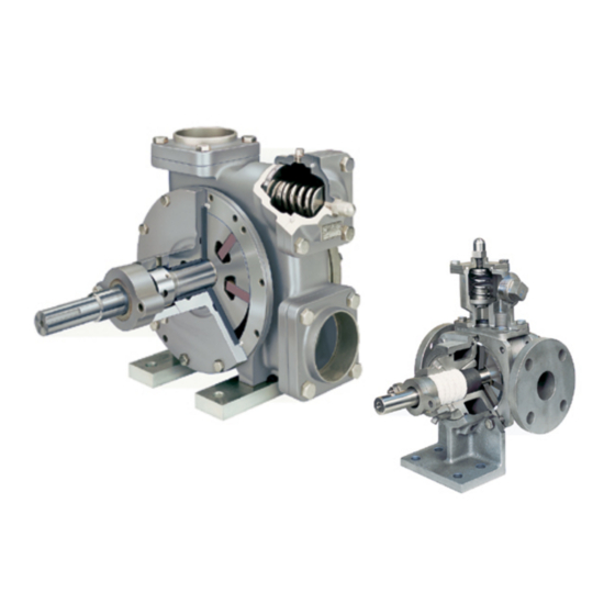
BLACKMER POWER PUMPS
INSTALLATION OPERATION AND MAINTENANCE INSTRUCTIONS
MODELS: SNP1.25, SNP1.5, SNP2, SNP2.5, SNP3A
SNPJ1.25 *, SNPJ1.5 *, SNPJ2 *, SNPJ2.5 *
TABLE OF CONTENTS
Technical Data ...................................................... 2
Initial Pump Start Up Information........................... 2
Pre-Installation Cleaning ....................................... 3
Location and Piping............................................... 3
Pump Mounting ..................................................... 4
Coupling Alignment ............................................... 4
Pump Rotation....................................................... 4
To Change Pump Rotation.................................... 4
Check Valves ........................................................ 4
Jacketed Heads..................................................... 4
Pre-Start Up Check List......................................... 5
Start Up Procedures.............................................. 5
Running the Pump in Reverse Rotation ................ 6
Flushing the Pump ................................................ 6
Pump Relief Valve................................................. 7
Relief Valve Setting and Adjustment ..................... 7
Strainers................................................................... 8
Lubrication................................................................ 8
Vane Replacement................................................... 8
Pump Disassembly .................................................. 9
Parts Replacement................................................... 9
Pump Assembly ..................................................... 11
TROUBLE SHOOTING ................................................. 13
* Effective Jan 2006, jackets are considered an option and
no longer change the model number.
NOTE: Numbers in parentheses following individual parts
indicate reference numbers on Blackmer Parts List No.
104-A01, 104-A02, 104-A03 and 104-A04.
Blackmer pump manuals and parts lists may be obtained
from Blackmer's website (www.blackmer.com) or by
contacting Blackmer Customer Service.
When you see this symbol on the product, or in the manual,
look for one of the following signal words and be alert to the
potential for personal injury, death or major property damage
Warns of hazards that WILL cause serious personal injury,
Warns of hazards that CAN cause serious personal injury,
Page
Warns of hazards that CAN cause personal injury
Indicates special instructions which are very
Blackmer Pumps MUST only be installed in systems, which
have been designed by qualified engineering personnel.
The system MUST conform to all applicable local and
national regulations and safety standards.
This manual is intended to assist in the installation and
operation of the Blackmer SNP / SNPJ Series pumps, and
MUST be kept with the pump.
Pump service shall be performed by qualified technicians
ONLY. Service shall conform to all applicable local and
national regulations and safety standards.
Thoroughly review this manual, all instructions and hazard
warnings, BEFORE performing any work on the pump.
Maintain ALL system and pump operation and hazard
warning decals.
960255
INSTRUCTIONS NO. 104-A00
Section
Effective
Replaces
SAFETY DATA
This is a SAFETY ALERT SYMBOL.
death or major property damage.
death or major property damage.
or property damage.
NOTICE:
important and must be followed.
NOTICE:
104
May 2010
Oct 2007
Advertisement
Table of Contents

Related Manuals for BLACKMER SNP1.25


Summary of Contents for BLACKMER SNP1.25
-
Page 1: Table Of Contents
Flushing the Pump ..........6 This manual is intended to assist in the installation and Pump Relief Valve..........7 operation of the Blackmer SNP / SNPJ Series pumps, and Relief Valve Setting and Adjustment ..... 7 MUST be kept with the pump. -
Page 2: Pump Data
If replacement parts are needed, or if information pertaining to the pump is required, this data must be furnished to a Blackmer representative. TECHNICAL DATA *... -
Page 3: Installation
NOTICE: away or drop down. After pump has been in operation for Blackmer SNP Pump sizes 1.25, 1.5, 2 and 2.5 may or may a week or two, completely recheck alignment. not be fitted with an bolt-on relief valve. If the bolt-on relief valve is not supplied, an external bypass valve MUST be used. -
Page 4: Pump Mounting
INSTALLATION PUMP MOUNTING PUMP ROTATION A solid foundation reduces noise and vibration, and will NOTICE: improve pump performance. On permanent installations it is Confirm correct pump rotation by checking the pump recommended the pumping unit be secured by anchor bolts rotation arrows respective to piping flow direction. -
Page 5: Operation
Operation without guards in place can Verify proper coupling alignment. cause serious personal injury, major property damage, or death. Blackmer helical gear reducers (if supplied) are shipped from the factory without oil in the gearcase. Fill with the Do not operate without guard grade of oil indicated on the reducer tag. -
Page 6: Running The Pump In Reverse Rotation
OPERATION RUNNING THE PUMP IN REVERSE ROTATION FLUSHING THE PUMP NOTICE: NOTICE: Operate the pump in reverse rotation for no more than 10 If flushing fluid is to be left in the pump for an extended minutes and only when a separate pressure relief valve time, it must be a lubricating, non-corrosive fluid. -
Page 7: Pump Relief Valve
MUST be fitted. Refer to the individual Blackmer pump parts lists for various The 3“ SNP is fitted with an internal pressure relief valve that spring pressure ranges. Unless specified otherwise, pumps bypasses internally back to the suction side of the pump. -
Page 8: Maintenance
Sleeve bearings (bushings) are lubricated by the liquid being adjusting the shaft packing can cause pumped. Additional lubrication is not required. severe personal injury. IF EQUIPPED: Blackmer gear reducers are shipped from the Hazardous factory without oil in the gearcase. Fill with the grade of oil machinery can cause serious indicated on the reducer tag. -
Page 9: Pump Disassembly
MAINTENANCE PUMP DISASSEMBLY PUMPS EQUIPPED WITH BLACKMER TRIPLE-LIP NOTICE: SEAL OR A COMMERCIAL MECHANICAL SEAL Follow all hazard warnings and instructions provided in Loosen all setscrews before removing the head the “Maintenance” section of this manual. assembly. For further instructions on the... - Page 10 MAINTENANCE Figure 7b – Sleeve Bearing Installation SLEEVE BEARINGS (Bushings) If the sleeve bearing has been removed from the head, a new bearing must be installed. To aid installation, heat the head in an oven at 200°F (93°C) before installing the bearing. Coat the new bearing with a quality grade of bearing grease, and place it on the inside face of the head with the notched end UP.
-
Page 11: Pump Assembly
MAINTENANCE PUMP ASSEMBLY Rotor and Shaft Before reassembling the pump, inspect all component Install the pushrods and the 2 (or 3) bottom vanes parts for wear or damage, and replace as required. Wash into the rotor. The rounded edge of the vanes must out the bearing/seal recess of the head and remove any be ouward to contact the bore of the cylinder and the relief grooves facing in the direction of rotation. - Page 12 Install the relief valve spring (8) and spring guide (7) 10. BLACKMER TRIPLE-LIP SEAL (if equipped) against the valve. On pumps equipped with a Blackmer triple-lip seal, refer to the Attach a new relief valve gasket (10) and the valve separate literature accompanying the triple-lip seal for cover (4) on the relief valve body (6).
-
Page 13: Troubleshooting
TROUBLESHOOTING NOTICE: Maintenance shall be performed by qualified technicians only, following the appropriate procedures and warnings as presented in this manual. LEAKAGE Location Probable Cause/Corrective Action Between the head & casing Damaged head O-ring: Inspect and replace if necessary. Burrs/dirt in head O-ring groove or cylinder: File and clean as necessary. - Page 14 TROUBLESHOOTING …. continued EXCESSIVE NOISE AND VIBRATION Probable Cause Corrective Action Cavitation or vaporization of the liquid resulting from Check for: • excessive vacuum on the pump due to starved suction. Inlet piping too long or too small in diameter. •...
- Page 15 NOTES 104-A00 Page 15/16...
- Page 16 Stainless Steel Sliding Vane Pumps Sliding Vane Pumps: 5 to 2200 GPM 1 to 265 GPM: Acids, Brines, Sugars, Syrups, Refined Fuels, Liquefied Gases, Solvents,Process Beer, Beet Juice, Cider, Flavor Extracts, etc. ® System One Centrifugal Pumps Magnetic Drive Pumps 10 to 7500 GPM;...
Need help?
Do you have a question about the SNP1.25 and is the answer not in the manual?
Questions and answers