Table of Contents
Advertisement
Quick Links
Advertisement
Table of Contents

Related Manuals for Verano VER-24 s


Summary of Contents for Verano VER-24 s
- Page 1 User manual VER-24 s...
-
Page 2: Table Of Contents
SPIS TREŚCI Safety..................................3 Device description ..............................4 III. Installation .................................. 5 Principle of operation ..............................7 Main screen description ............................. 8 Controller operation modes ............................9 VII. Controller functions ..............................9 Block diagram of main menu ........................... 9 Profile selection ..............................11 Temperature settings ............................ -
Page 3: Safety
SAFETY Before using the device for the first time the user should read the following regulations carefully. Not obeying the rules included in this manual may lead to personal injuries or controller damage. The user’s manual should be stored in a safe place for further reference. -
Page 4: Device Description
II. DEVICE DESCRIPTION VER-24 S regulator enables convenient control of Verano fan-coil. VER-24 S offers the following functions: Room temperature control (heating/cooling) Smooth control of fan speed Smooth control of the actuator (0-10) ON/OFF actuator control ... -
Page 5: Installation
VER-24 S regulator is intended to be installed on the wall. First, attach the back cover to the wall in the place where the room regulator in the electrical box will be installed. Next, connect the power supply wires and mount the device on the latches. - Page 6 Power supply 24V 0-10V signal-controlled fan 0-10V signal-controlled actuator NC actuator NO actuator 2. How to connect NO actuator 3. How to connect NC actuator...
-
Page 7: Principle Of Operation
In order to remove the back cover, disconnect the tape between the printed circuit board and the regulator. IV. PRINCIPLE OF OPERATION VER-24 S controls the fan and the valves in order to maintain the pre-set room temperature. Depending on selected operation mode, the device may increase the temperature (heating mode) or decrease the temperature (cooling mode). -
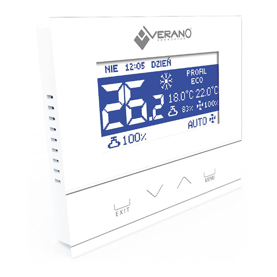
Page 8: Main Screen Description
V. MAIN SCREEN DESCRIPTION The main screen displays current status of basic controller parameters. 1. Day of the week and time 2. Operation mode change: - Heating– sun icon - Cooling – snowflake icon NOTE This function is active when Manual heating/cooling option is selected in the service menu, in Mode selection submenu. -
Page 9: Controller Operation Modes
VI. CONTROLLER OPERATION MODES Regardless of the selected profile, the controller may operate in two modes: heating or cooling. In Service settings/Mode selection submenu the user configures mode selection. The user may select one operation mode - by selecting heating or cooling or allow manual mode change from the main screen view - by selecting Manual heating/cooling. - Page 10 Comfort Protection Profile selection Schedule 1 Schedule 2 Schedule 3 Weekly schedule Comfort temperature ECO min temperature Temperature settings ECO max temperature Protection min temperature Protection max temperature Clock settings Time settings Date settings Schedule 1 Schedule 2 Schedule settings Schedule 3 Weekly schedule Display contrast...
-
Page 11: Profile Selection
PROFILE SELECTION The parameters in this submenu are used to select the controller operation profile. The profiles offered by the controller are used to maintain the room temperature at a pre-defined level. The user may choose from 3 profiles (comfort, eco, protection), 3 daily schedules (1,2,3) and a weekly schedule. ... - Page 12 ECO, PROTECTION - PROTECTION profile functions similarly to ECO profile. The only difference is the default pre-set temperature values: PROTECTION min temperature < ECO min temperature PROTECTION max temperature > ECO max temperature PROTECTION profile is intended for maintaining optimum room parameters in order to protect the heating/cooling system against freezing or overheating.
-
Page 13: Temperature Settings
Schedule 1,2,3 profile - If one of the schedules is activated, the controller functions according to pre-defined program - Schedule settings parameter. Schedules enable the user to select the desired profile (comfort, eco, protection) for particular hours of the day (Menu/Schedule settings). -
Page 14: Screen Settings
SCREEN SETTINGS This submenu enables the user to adjust the screen settings to individual needs. Display contrast – it enables the user to adjust the screen contrast (percent). Screen brightness– it enables the user to adjust the screen brightness (percent). -
Page 15: Controller Settings
CONTROLLER SETTINGS Room sensor - This submenu enables the user to calibrate the room temperature sensor. Sensor calibration is performed while mounting or after the regulator has been used for a long time, if the room temperature displayed differs from the actual temperature. Calibration range is from -10⁰C to +10⁰C with the accuracy of 0,1⁰C. -
Page 16: Protections
Cooling: CT – cooling threshold CH– cooling hysteresis When the threshold temperature is 23°C, and the cooling hysteresis is set at 2°C, the fan is enabled when the additional sensor temperature drops to CT value. The fan is disabled when the temperature exceeds 25°C (HT+HH). PROTECTIONS When this option is selected, it opens up a panel which enables the user to configure parental lock settings. -
Page 17: Service Settings
SERVICE SETTINGS Service settings are used to configure advanced controller parameters and this submenu should be accessed by a qualified person. Detailed description of these parameters in included in the following section. Access to this submenu is secured with a 4-digit code. FACTORY SETTINGS This function enables the user to restore factory settings in the main menu (excluding the service settings). -
Page 18: Temperature Settings
TEMPERATURE SETTINGS The parameters in this submenu are used to set the temperature delta value for particular operation profiles. Delta indicates the moment when the controller starts smooth control of the valve and the fan - it is described in detail in Profile selection section. -
Page 19: Output Configuration
OUTPUT CONFIGURATION These parameters are used to configure output functioning: Output 01 These settings concern the operation of the valve controlled via ON/OFF output. In Output type the user defines the function of the valve: - Heating – when this option is selected, the valve controlled via ON/OFF output will operate in heating mode. - Cooling –... -
Page 20: Fan Advanced Settings
FAN ADVANCED SETTINGS The parameters in this submenu are used to configure fan operation. • Heating activation temperature This parameter defines how the fan adjustment range will move down in relation to the pre-set temperature in heating mode. • Heating adjustment range This parameter defines the temperature range width within which the controller will smoothly adjust the fan speed in heating mode. -
Page 21: Factory Settings
In the above example, the valve will be open until the temperature of 19⁰C is reached in the room (SetT - comfort delta). Once this value has been reached, the valve will start closing gradually. When the pre-set room temperature is reached, the valve will close completely. -
Page 22: Alarms
IX. ALARMS VER-24S room temperature regulator signalises all alarms which occur in the controller. When an alarm occurs, the room regulator will send a sound signal and an appropriate message will appear on the screen. In the event of an alarm, all outputs are disabled. - Page 23 EU Declaration of conformity Hereby, we declare under our sole responsibility that VER-24s manufactured by TECH, headquartered in Wieprz Biała Droga 31, 34-122 Wieprz, is compliant with: • Directive 2014/35/EU of the European Parliament and of the Council of February 26, 2014 on the harmonisation of the laws of Member States relating to the making available on the market of electrical equipment designed for use within certain voltage limits (EU Journal of Laws L 96, of 29.03.2014, p.
- Page 24 The manufacturer reserves the right to modify the design or change the colour of the product. The illustrations may include additional equipment. Colours may differ slightly from those shown in the manual, owing to the limitations of the printing process. For up-to- date information, contact sales representatives of Verano-konwektor.
Need help?
Do you have a question about the VER-24 s and is the answer not in the manual?
Questions and answers