Advertisement
Quick Links
This is the Original Document in English Language
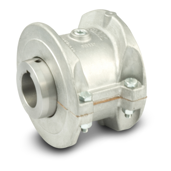
Sizes 1020-1170
Figure 1 - Steelflex T10 & T20 coupling range
1.
General Information
1.1.
Falk Steelflex Couplings are designed to provide a mechanical connection between the rotating shafts of mechanical equipment,
using a grid spring to accommodate inherent misalignment while transmitting the power and torque between the connected
shaft.
1.2.
These instructions are intended to help you to install and maintain your Falk Steelflex coupling. Please read these instructions prior to
installing the coupling, and prior to maintenance of the coupling and connected equipment. Keep these instructions near the coupling
installation and available for review by maintenance personnel. For special engineered couplings, Rexnord may provide an engineering
drawing containing installation instructions that take precedence over this document.
1.3.
Rexnord Industries, LLC owns the copyright of this material. These Installation and Maintenance instructions may not be reproduced in
whole or in part for competitive purposes.
1.4.
Symbol descriptions:
Danger of injury to persons.
Damages on the machine possible.
Pointing to important items.
Hints concerning explosion protection.
Rexnord Industries, LLC, 5555 S. Moorland Rd., New Berlin, WI 53151-7953
Telephone: 262-796-4060 Fax: 262-796-4064
e-mail: info@rexnord.com web: www.rexnord.com
Installation and Maintenance Instructions
Type T10
Type T20
Supersedes manuals 428-110, 112, 110 - 04/2005
•
Falk Steelflex
Type T10 & T20 (Page 1 of 9)
Type T10
Sizes 1150-1260
428-111
02/2012
®
Advertisement

Related Manuals for Rexnord Falk Steelflex T10


Summary of Contents for Rexnord Falk Steelflex T10
- Page 1 For special engineered couplings, Rexnord may provide an engineering drawing containing installation instructions that take precedence over this document. 1.3. Rexnord Industries, LLC owns the copyright of this material. These Installation and Maintenance instructions may not be reproduced in whole or in part for competitive purposes. 1.4.
- Page 2 2.11. The coupling may only be used in accordance with the technical data provided in the Falk Steelflex coupling catalog. Customer modifications and alterations to the coupling are not permissible. 2.12. All spare parts for service or replacement must originate from or be approved by Rexnord Industries, LLC. 428-111 Rexnord Industries, LLC, 5555 S.
- Page 3 Figure 2 - Falk Steelflex Coupling Components 428-111 Rexnord Industries, LLC, 5555 S. Moorland Rd., New Berlin, WI 53151-7953 Telephone: 262-796-4060 Fax: 262-796-4064 02/2012 e-mail: info@rexnord.com web: www.rexnord.com Supersedes manuals 428-110, 112, 110 - 04/2005...
- Page 4 5.3. Slide the hub up the shaft to the desired axial position. 428-111 Rexnord Industries, LLC, 5555 S. Moorland Rd., New Berlin, WI 53151-7953 02/2012 Telephone: 262-796-4060 Fax: 262-796-4064 Supersedes manuals 428-110, 112, 210 - 04/2005...
- Page 5 7.10. With the hub expanded, install it quickly on the shaft to the “zero” set point. Continue to advance the hub up the taper to the desired axial position, as defined by Rexnord’s customer. Use the indicator as a guide only. A pre-set axial stop device can be helpful.
-
Page 6: Shaft Alignment
Tables 4 and 5. Shaft alignment can be measured using various established methods, including Laser Alignment, Reverse Dial Indicator, and Rim and Face. Refer to Rexnord bulletin 538-214 “Coupling Alignment Fundamentals” for instructions regarding shaft alignment. - Page 7 1170). Line up cover and gasket bolt holes and secure with fasteners; tighten to torque specified in Table 6 Type T10 Type T20 428-111 Rexnord Industries, LLC, 5555 S. Moorland Rd., New Berlin, WI 53151-7953 Telephone: 262-796-4060 Fax: 262-796-4064 02/2012 e-mail: info@rexnord.com web: www.rexnord.com...
- Page 8 – groove area of Steelflex couplings resulting in premature hub or grid failure unless periodic lubrication cycles are maintained. 428-111 Rexnord Industries, LLC, 5555 S. Moorland Rd., New Berlin, WI 53151-7953 02/2012 Telephone: 262-796-4060 Fax: 262-796-4064 Supersedes manuals 428-110, 112, 210 - 04/2005 e-mail: info@rexnord.com web: www.rexnord.com...
- Page 9 (LTG) will allow relube intervals to be extended to beyond five years. When relubing, remove both lube plugs and insert lube fitting. Fill with recommended lubricant until an excess appears at the opposite hole. 428-111 Rexnord Industries, LLC, 5555 S. Moorland Rd., New Berlin, WI 53151-7953 Telephone: 262-796-4060 Fax: 262-796-4064 02/2012 e-mail: info@rexnord.com web: www.rexnord.com...
Need help?
Do you have a question about the Falk Steelflex T10 and is the answer not in the manual?
Questions and answers