
Related Manuals for Beckhoff BC**50 Series


Summary of Contents for Beckhoff BC**50 Series
- Page 1 Documentation BC5250 Bus Terminal Controller for DeviceNet Version: 2.0.0 Date: 2017-07-18...
-
Page 3: Table Of Contents
Safety instructions .......................... 6 Documentation issue status...................... 7 2 Product overview............................ 8 BCxx50 Overview ........................... 8 The principle of the Bus Terminal .................... 9 The Beckhoff Bus Terminal system .................... 9 Technical data .......................... 12 2.4.1 Technical Data - BCxx50 .................... 12 2.4.2 Technical data - DeviceNet .................... 14... - Page 4 Table of contents 5.12.1 Libraries overview ...................... 64 5.12.2 Data structure strBX5200_Set .................. 65 5.12.3 TcBaseBX ........................ 67 5.13 Program transfer via the serial interface.................. 71 6 DeviceNet communication........................ 73 DeviceNet Introduction ......................... 73 Network Management........................ 74 Object directory.......................... 74 ADS-Communication ........................ 75 6.4.1 ADS services........................ 75 7 Error handling and diagnosis......................... 77 Diagnostics ...........................
-
Page 5: Foreword
The TwinCAT Technology is covered, including but not limited to the following patent applications and patents: EP0851348, US6167425 with corresponding applications or registrations in various other countries. ® EtherCAT is registered trademark and patented technology, licensed by Beckhoff Automation GmbH, Germany Copyright © Beckhoff Automation GmbH & Co. KG, Germany. -
Page 6: Safety Instructions
All the components are supplied in particular hardware and software configurations appropriate for the application. Modifications to hardware or software configurations other than those described in the documentation are not permitted, and nullify the liability of Beckhoff Automation GmbH & Co. KG. Personnel qualification This description is only intended for trained specialists in control, automation and drive engineering who are familiar with the applicable national standards. -
Page 7: Documentation Issue Status
Foreword Documentation issue status Version Comment 2.0.0 • Migration 1.1.0 • Notes to meet the UL requirements added. 1.0.0 • First public issue BC5250 firmware For updating your firmware you need a serial cable, the KS2000 configuration software, or the firmware update program. -
Page 8: Product Overview
The BCxx50 devices are programmed according to the powerful IEC 61131-3 standard. Like for all other BECKHOFF controllers, the TwinCAT automation software is the basis for parameterization and programming. Users therefore have the familiar TwinCAT tools available, e.g. PLC programming interface, System Manager and TwinCAT Scope. -
Page 9: The Principle Of The Bus Terminal
The principle of the Bus Terminal Fig. 1: The principle of the Bus Terminal The Beckhoff Bus Terminal system Up to 256 Bus Terminals, with 1 to 16 I/O channels per signal form The Bus Terminal system is the universal interface between a fieldbus system and the sensor / actuator level. - Page 10 Bus Couplers for all usual bus systems The Beckhoff Bus Terminal system unites the advantages of a bus system with the possibilities of the compact series terminal. Bus Terminals can be driven within all the usual bus systems, thus reducing the controller parts count.
- Page 11 Product overview outputs return in the inactive state. The timeout periods for the Bus Couplers correspond to the usual settings for the fieldbus system. When converting to a different bus system it is necessary to bear in mind the need to change the timeout periods if the bus cycle time is longer. The interfaces A Bus Coupler has six different methods of connection.
-
Page 12: Technical Data
Product overview Technical data 2.4.1 Technical Data - BCxx50 Technical data BCxx5x Processor 16 bit micro-controller Diagnostics LEDs 2 x power supply, 2 x K-Bus Configuration and programming software TwinCAT PLC Fieldbus interface BC3150 Fieldbus PROFIBUS DP Interfaces Serial interface COM1 (RS232 for configuration and programming, automatic baud rate detection 9600/19200/38400 baud) Terminal Bus (K-Bus) 64 (255 with K-bus extension) - Page 13 Product overview Technical data BC3150 Digital peripheral signals 2040 inputs/outputs Analog peripheral signals 128 inputs/outputs Configuration possibility via TwinCAT or the controller Maximum fieldbus byte number 512 bytes input and 512 bytes output Maximum number of bytes - PLC 2048 bytes of input data, 2048 bytes of output data Bus connection D-sub, 9-pin Power supply (Us)
-
Page 14: Technical Data - Devicenet
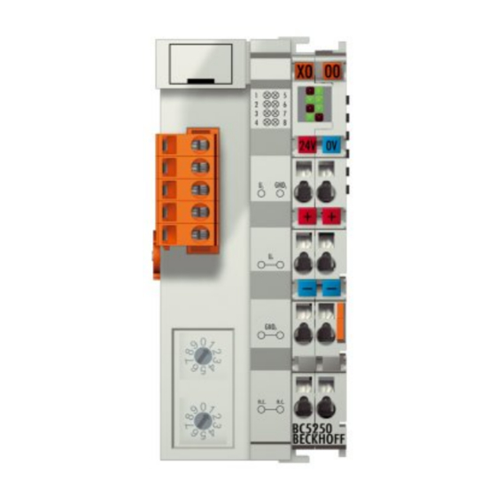
Product overview 2.4.2 Technical data - DeviceNet Fig. 2: BC5250 System data DeviceNet (BC5250) Number of nodes Number of I/O points depending on controller Data transfer medium shielded, twisted copper cable, 2 x signal, 1 x CAN ground (recommended) Cable length 500 m 250 m 100 m... -
Page 15: Technical Data - Plc
Product overview 2.4.3 Technical Data - PLC PLC data BCxx5x Programmability via serial programming interface or via the fieldbus Program memory 48 kbyte Source code memory 128 kbyte Data memory 32 kbyte Remanent flags 2 kbyte PLC cycle time Approx. 3.0 ms for 1000 IL commands (without I/O cycle) Programming languages IEC 6-1131-3 (IL, LD, FBD, ST, SFC) Runtime... -
Page 16: Mounting And Wiring
3.1.1 Dimensions The Beckhoff Bus Terminal system is characterized by low physical volume and high modularity. When planning a project it must be assumed that at least one Bus Coupler and a number of Bus Terminals will be used. The mechanical dimensions of the Bus Couplers are independent of the fieldbus system. -
Page 17: Installation
Mounting and wiring 3.1.2 Installation The Bus Coupler and all the Bus Terminals can be clipped, with a light press, onto a 35 mm mounting rail. A locking mechanism prevents the individual housings from being pulled off again. For removal from the mounting rail the orange colored tension strap releases the latching mechanism, allowing the housing to be pulled off the rail without any force. -
Page 18: Wiring
3.2.1 Potential groups, insulation testing and PE Potential groups A Beckhoff Bus Terminal block usually has three different potential groups: • The fieldbus interface is electrically isolated (except for individual Low Cost couplers) and forms the first potential group. • Bus Coupler / Bus Terminal Controller logic, K-bus and terminal logic form a second electrically isolated potential group. -
Page 19: Fig. 7 Power Contact On The Left
Mounting and wiring Fig. 7: Power contact on the left It should be noted that, for reasons of electromagnetic compatibility, the PE contacts are capacitively coupled to the mounting rail. This can both lead to misleading results and to damaging the terminal during insulation testing (e.g. -
Page 20: Power Supply
Mounting and wiring 3.2.2 Power supply Risk of injury through electric shock and damage to the device! Bring the Bus Terminals system into a safe, de-energized state before starting mounting, disassembly or wiring of the components! DANGER Supply of Bus Terminal Controller and Bus Terminals (Us) The Bus Terminal Controller requires a supply voltage of 24 V The connection is made by means of the upper spring-loaded terminals labelled 24 V and 0 V. -
Page 21: Programming Cable
Mounting and wiring No unlimited voltage sources! To comply with the UL requirements, Us must not be connected with unlimited voltage sources. DANGER Power contacts supply (Up) The bottom six connections with spring-loaded terminals can be used to feed the supply for the peripherals. The spring-loaded terminals are joined in pairs to a power contact. -
Page 22: Devicenet Cabling
Mounting and wiring 3.2.4 DeviceNet cabling 3.2.4.1 DeviceNet topology CAN is a 2-wire bus system, to which all participating devices are connected in parallel (i.e. using short drop lines). The bus must be terminated at each end with a 120 (or 121) Ohm termination resistor to prevent reflections. -
Page 23: Fig. 13 Sample Topology Of Drop Lines
Shorter drop line lengths must be maintained when passive distributors ("multiport taps"), such as the Beckhoff ZS5052-4500 Distributor Box. The following table indicates the maximum drop line lengths and the maximum length of the trunk line (without the drop lines):... -
Page 24: Fig. 14 Structure Of Can/Devicenet Cable Zb5200
Notes related to checking the CAN wiring can be found in the Trouble Shooting section. 3.2.4.7 Cable colors Suggestion for using the Beckhoff DeviceNet cables at the Bus Terminal and the Fieldbus Box: BK52x0 pin Fieldbus Box pin FC520x pin... -
Page 25: Fig. 15 Bk51X0/Bx5100 Connection Socket Assignment
Mounting and wiring 3.2.4.9 BK52x0/BX5200: 5-pin open style connector The BK52x0/BX5200 (X520) Bus Couplers have a recessed front surface on the left hand side with a five pin connector. The supplied DeviceNet connecting socket can be inserted here. Fig. 15: BK51x0/BX5100 connection socket assignment The left figure shows the socket in the BK52x0/BX5200 Bus Coupler. -
Page 26: Fig. 16 Pin Assignment: M12 Plug, Fieldbus Box
Fig. 16: Pin assignment: M12 plug, fieldbus box BECKHOFFoffer plugs for field assembly, passive distributor's, termination resistors and a wide range of preassembled cables for the Fieldbus Box system. Details be found in the catalog, or under www.beckhoff.de Version: 2.0.0 BC5250... -
Page 27: Parameterization And Commissioning
Parameterization and Commissioning Parameterization and Commissioning Start-up behavior of the Bus Terminal Controller When the Bus Terminal Controller is switched on it checks its state, configures the K-bus, creates a configuration list based on the connected Bus Terminals and starts its local PLC. The I/O LEDs flash when the Bus Terminal Controller starts up. - Page 28 Parameterization and Commissioning The complex Bus Terminals are mapped as follows: • Word Alignment • complex representation The process image depends on the connected terminals! The process image changes when a terminal is added or removed! CAUTION The data of the fieldbus slaves interface are referred to as PLC variables. The PLC variables have addresses from %QB1000 and %IB1000 The DEFAULT CONFIG (without PLC program) can also be used for writing and testing of the Connected Bus Terminals.
-
Page 29: Creating A Twincat Configuration
Parameterization and Commissioning The TwinCAT configuration can be used to link variables, I/Os and data. The following is possible: • PLC - K-BUS • PLC fieldbus (e.g. PROFIBUS slave interface to PLC) • K-bus fieldbus (only for BX controllers) • Support for TwinSAFE terminals (only BX controllers from firmware 1.17) In addition, the TwinCAT configuration can be used to parameterize special behavior, for example whether data are preserved or set to "0"... -
Page 30: Downloading A Twincat Configuration
Parameterization and Commissioning Fig. 19: Selecting the Bus Terminal Controller All Bus Terminal Controller components are now available: • Fieldbus interface • K-bus interface [} 45] • PLC Program [} 47] • SSB (only Bus Terminal Controllers of the BX series) Please refer to the relevant chapter for device configuration. 4.2.3 Downloading a TwinCAT configuration The TwinCAT configuration is loaded into the Bus Terminal Controller via ADS protocol. -
Page 31: Fig. 20 Downloading A Twincat Configuration
Parameterization and Commissioning Fig. 20: Downloading a TwinCAT configuration Select the corresponding Bus Terminal Controller. Fig. 21: Selecting the Bus Terminal Controller The state of the Bus Terminal Controller is shown at the bottom right of the System Manager. Fig. 22: State of the Bus Terminal Controller In Config mode / FreeRun the configuration can now be downloaded to Bus Terminal Controller. -
Page 32: Uploading A Twincat Configuration
Parameterization and Commissioning The current configuration is loaded onto the Bus Terminal Controller. The display will show Store Config, and the BUS and I/O LED will flash. Once the configuration is successfully loaded onto Bus Terminal Controller, TwinCAT Config should appear in the display of a BXxx00. The corresponding program can now be transferred to the Bus Terminal Controller (program-download via the fieldbus). -
Page 33: Resources In The Bus Terminal Controller
Parameterization and Commissioning Fig. 25: Selecting the Bus Terminal Controller The state of the Bus Terminal Controller is shown at the bottom right of the System Manager. Fig. 26: State of the Bus Terminal Controller Click on the red folder. The TwinCAT configuration will now be uploaded. Fig. 27: Uploading the TwinCAT configuration 4.2.5 Resources in the Bus Terminal Controller... -
Page 34: Fig. 28 Memory For Code Mapping
Parameterization and Commissioning Fig. 28: Memory for code mapping Data memory mapping Data memory for mapping. The values are to be considered individually, i.e. each value can be up to 100%. Fig. 29: Data memory mapping Used code and data memory Fig. Code and data memory (1) "Used PLC code" in %. Fig. -
Page 35: Fig. 30 Code And Data Memory
Parameterization and Commissioning Fig. 30: Code and data memory Other memory Fig. Other Memory (1) "Used Near Heap" is required for the COM interface and SSB. % values. Fig. Other Memory (2) "Used Huge Heap" is required for the ADS communication. % values. This value should be less than 30 %. -
Page 36: Ads Connection Via Serial Interface
Parameterization and Commissioning 4.2.6 ADS connection via serial interface (from firmware version 1.xx or 0.99x, Bus Terminal Controllers of the BX series and for all BCxx50) From TwinCAT 2.9 build 1020 (TwnCAT level PLC, NC or NCI) Use only a serial connection To ensure trouble-free operation of the ADS link via the serial interface, only a serial con- nection to the BX controller is allowed. -
Page 37: Devicenet Slave Interface
4.2.7 DeviceNet slave interface 4.2.7.1 DeviceNet slave interface EDS file BX5200 EDS file BX5200.eds (for controllers other than TwinCAT) (https://infosys.beckhoff.com/content/1033/ bc5250/Resources/eds/3602698891.eds) EDS file BX5200S.eds (https://infosys.beckhoff.com/content/1033/bc5250/Resources/ eds/3602698891.eds) For TwinCAT both EDS files must be copied into the directory TwinCAT\IO\DeviceNet . Image for BX5200.ico (https://infosys.beckhoff.com/content/1033/bc5250/Resources/ zip/3602701067.zip) - Page 38 Parameterization and Commissioning 4.2.7.2 DeviceNet slave interface There are two types of configuration. In the default configuration (delivery state) the DeviceNet data of the DeviceNet Slave interface map from the address 1000 of the BX5200/BC5250 and the first 8 bytes are activated.
-
Page 39: Fig. 33 Setting The Node Id
Parameterization and Commissioning 4.2.7.4 Address The address of the DeviceNet Slave interface is set via two rotary selection switches. The default setting is 11. All addresses from 0 to 63 are permitted. Each address may only occur once in the network. The address is edited when the BX Controller is switched off. -
Page 40: Fig. 34 Eds Wizard
Parameterization and Commissioning The EDS file and the icon file are always integrated in the RSNetworx with the EDS wizard: Fig. 34: EDS Wizard Finally the DeviceNet network is searched with the Network-Browse for the nodes within the network. If the BC/BX are correctly connected to the network with the correct baud rate, they are recognized and correspondingly displayed: Version: 2.0.0... -
Page 41: Fig. 35 Network Browse
Parameterization and Commissioning Fig. 35: Network Browse Double-clicking the icon opens the configuration dialog for the units. Below Parameter appear the I/O data lengths that are currently set at the BC/BX. Fig. 36: I/O data lengths set on the BC/BX BC5250 Version: 2.0.0... -
Page 42: Fig. 37 Adoption Of The Detected Modules Into The Scan List
Parameterization and Commissioning The produced and consumed data should always be considered from the point of view of the network, i.e. BC/BX produce data for DeviceNet and consume data from DeviceNet. • The data produced are thus the input data of the master, i.e. data that are sent from the BC/BX to the master: BC/BX Produced Size = Input Size Scanner •... -
Page 43: Fig. 38 Setting Of The I/O Data Lengths
Parameterization and Commissioning Fig. 38: Setting of the I/O data lengths • BC/BX Produced-Size = Input-Size • BC/BX Consumed-Size = Output-Size Furthermore, it must be ensured that the I/O operation mode selected here corresponds to the I/O mode selection. The Interscan Delay, that is the time between each I/O cycle, must be selected according to the requirements of the BC/BX with respect to the size of the PLC program and the I/O data lengths. -
Page 44: Fig. 39 Selection Of The Interscan Delay
Parameterization and Commissioning Fig. 39: Selection of the interscan delay If there are components in the network that require a fast I/O cycle, the I/O cycle can be set to Background under Poll Rate in the I/O parameter settings. More detailed information about this can be obtained from the scanner manual. -
Page 45: K-Bus
Parameterization and Commissioning 4.2.8 K-bus Bus Terminal and end terminal required To operate a Bus Terminal Controller of the BC or BX series, at least one Bus Terminal with process image and the end terminal must be connected to the K-bus. Note BX Settings tab Fig. 41: BX Settings tab... -
Page 46: Fig. 42 Bx Diag Tab
Parameterization and Commissioning K-Bus Re-Trigger If the processor is busy dealing with the PLC project or the SSB, the K-Bus cannot be processed for a certain amount of time. This leads to triggering of the Bus Terminal watchdog and dropping of the outputs. The Bus Terminal Controller is set such that the K-bus watchdog is re-triggered 3 times after 85 ms. -
Page 47: Plc
Parameterization and Commissioning K-Bus variables PLC interface: Not supported (only included for moving CX or BX projects) K-bus state: see Diagnostics 4.2.9 4.2.9.1 Inserting a PLC project For variable mapping, configuration has to be specified in the system manager. This is where the link between PLC and hardware is specified. -
Page 48: Fig. 44 Connecting Plc Variable And Hardware
Parameterization and Commissioning Fig. 44: Connecting PLC variable and hardware Once all links have been created, activate the configuration Actions/Activate Configuration (Ctrl+Shift+F4) and start TwinCAT Set/Reset TwinCAT to Run Mode. Ensure that you have selected the correct target system (bottom right in the System Manager window). Fig. 45: Target system display Version: 2.0.0 BC5250... -
Page 49: Fig. 46 Setting The Task Time
Parameterization and Commissioning 4.2.9.2 Measuring the PLC cycle time The task time is set in PLC Control. The default setting is 20 ms. Fig. 46: Setting the task time In the default setting, the PLC program is called every 20 ms, as long as the general cycle time is less than 20 ms. -
Page 50: Configuration Software Ks2000
Parameterization and Commissioning Fig. 47: Displaying the PLC cycle time 4.2.10 Configuration software KS2000 Bus Terminal controllers of the BCxx50, BXxx20 and BXxx00 series cannot be parameterized and configured with the KS2000 configuration software. These devices must be configured with the TwinCAT System Manager. -
Page 51: Programming
Limited by memory TwinCAT PLC The Beckhoff TwinCAT Software System turns any compatible PC into a real-time controller with a multi-PLC system, NC axis control, programming environment and operating station. The TwinCAT programming environment is also used for programming the BC/BX. If you have TwinCAT PLC (Windows NT4/2000/XP) installed, you can use the fieldbus connection or the serial port for downloading and debugging software. -
Page 52: Twincat Plc - Error Codes
Programming • Controller memory limit is almost reached (PLC program greater than 90%) TwinCAT PLC - Error codes Error type Description PLC compiler error Maximum number of POUs (...) exceeded PLC compiler error Out of global data memory ... Error POUs For each function block one POU (process object unit) is created. -
Page 53: Fig. 50 Controller Settings
Programming Fig. 50: Controller settings Changing these settings will deactivate online changes. Global memory error Fig. 51: Global memory insufficient 2 x 16 kbyte of data are available by default. If large data quantities are to be used, this range should be increased. A maximum of 14 data segments are possible for the BX. Fig. 52: Menu path Projects / Options / Build BC5250 Version: 2.0.0... -
Page 54: Remanent Data
Programming Fig. 53: Build Remanent data 2000 kbyte of remanent data are available for the BX controller. These data are declared as VAR RETAIN in PLC Control: Example VAR RETAIN Test :BOOL; Count :INT; END_VAR Retain data are located between VAR RETAIN and END_VAR. These data are stored in a NOVRAM and are consistent across the whole 2 kbyte range. -
Page 55: Allocated Flags
Programming END_VAR VAR_IN_OUT Counter :INT; END_VAR MAIN program PROGRAM MAIN fb_Test:Test; END_VAR VAR RETAIN iCounter1:INT; END_VAR fb_Test(Counter:=iCounter1); Allocated flags 4 kbyte of allocated flags are available. They can be used to assign different variable types to the same address, e.g. for converting strings to bytes. Data can also be placed here that can be read or written via ADS by the controller. -
Page 56: Local Process Image In Delivery State
Programming Local process image in delivery state The process image of the BX and BCxx50 series consists of input, output and flag areas. In addition, there are unallocated data without fixed address. They are created without specifying an address. For these variable types the memory allocation is as follows: •... -
Page 57: Mapping The Bus Terminals
Mapping the Bus Terminals The precise assignment of the byte-oriented Bus Terminals may be found in the configuration guide for the particular bus terminal. This documentation is available on the Beckhoff Products & Solutions CD or on the Internet under http://www.beckhoff.de. Byte oriented Bus Terminals... -
Page 58: Local Process Image In The Twincat Configuration
Programming • Creating a boot project (Online\Create boot project) The PLC LED lights up green once a valid boot project is available on the BX/BCxx50. In the Bus Terminal controllers of the BX series, the PLC LED flashes orange while boot project is created. The PLC LED lights up orange if no boot project is available on the BX. -
Page 59: Communication Between Twincat And Bx/Bcxx50
Programming Fig. 54: Changing variable links Fig. 55: Linking a variable with an input In the default configuration all Bus Terminals are assigned fixed addresses. If a Bus Terminal is inserted, the whole address range may be shifted. The TwinCAT configuration enables allocated variables to be linked to a Bus Terminal, as required. -
Page 60: Up- And Downloading Of Programs
Programming Example 1: A structure on the BX/BCxx50 and on the PC Variable BX/BCxx50 memory PC memory (TwinCAT) Byte %..B0 %..B0 INT (1) %..B2 %..B1 INT (2) %..B4 %..B3 Due to the fact that another variable type (INT) follows the first byte, in the BX/BCxx50 it was assigned the next free even address. -
Page 61: Fig. 56 Opening The Options Menu
Programming Fig. 56: Opening the options menu Select Source Download. Fig. 57: Selecting Source Download Here you can set which parts of the source code are to be downloaded to the Bus Terminal Controller, and when. Source code only: the prx file with information on the online change is transferred. Login via online change is possible (the PLC does not stop). -
Page 62: Fig. 58 Downloading The Program Code
Programming Fig. 58: Downloading the program code After a short delay, a window will open that indicates the download progress. Fig. 59: Download progress Uploading a program For uploading the program code again, open a new file in PLC Control. Then click on the PLC button. Version: 2.0.0 BC5250... -
Page 63: Fig. 60 Uploading A Program
Programming Fig. 60: Uploading a program Select the data transfer route: • BCxx50 or BX via AMS, if you are connected to the Bus Terminal Controller via the fieldbus, or • BCxx50 or BX via serial, if you are connected to the Bus Terminal Controller via the serial interface. Fig. 61: Selecting the data transfer route Then select the device and confirm with OK. -
Page 64: Libraries
Libraries overview The TwinCAT Automation Software offers various libraries for the BCxx50 series Bus Terminal Controllers (Bus Coupler with PLC functionality) (see BECKHOFF Information System). Download The libraries are also included in this documentation. To extract the libraries, left-click on the link and copy the libraries to directory TwinCAT\PLC\LIB. -
Page 65: Data Structure Strbx5200_Set
Programming Controller Version Firmware BC3150 BC5150 BC5250 BC8150 FB_BasicPID File Access Version Firmware BC3150 BC5150 BC5250 BC8150 FB_ReadFromFile FB_WriteToFile FB_ReadWriteFile Memory Functions Version Firmware BC3150 BC5150 BC5250 BC8150 MEMCMP MEMCYP MEMMOVE MEMSET NOVRAM Functions Version Firmware BX3100 BX5100 BX5200 BX8000 Version Firmware BC3150... -
Page 66: Fig. 63 Function Block Bxbc52X0_Settings
Programming (https://infosys.beckhoff.com/content/1033/bc5250/Resources/lbx/4007139723.lbx) • Example of BC5250 (https://infosys.beckhoff.com/content/1033/bc5250/Resources/prx/4007141899.prx) • Example of BX5200 (https://infosys.beckhoff.com/content/1033/bc5250/Resources/prx/4007144075.prx) BXBC52x0_Settings Fig. 63: Function block BXBC52x0_Settings Function block BXBC52x0_Settings VAR_INPUT bWriteSet :BOOL; bReadSet :BOOL; strDeviceNet_Set :DeviceNet_Set; bWriteSet: Rising edge starts the block and reads/writes the parameters if these have changed. The Bus Coupler must then be restarted. -
Page 67: Tcbasebx
Programming iERP :INT; (*100ms, ERP*4=Watchdog*) E_BaudRate :ENUM;(*0-125kBaud, 1-250kBaud, 2-500kBaud, 3-AutoBaud*) END_STRUCT END_TYPE )1 If the DN mode is only 8 Byte In and 8 Byte Output allowed. That is fix and you can´t change it. iInputData: Number of input data (from the point of view of the BX). Size in bytes [BX5200: 0..255 bytes, BC5250: 0..127 bytes] iOutputData: Number of output data (from the point of view of the BX). Size in bytes [BX5200: 0..255 bytes, BC5250: 0..127 bytes] E_Mode: DeviceNet Mode iERP: Expected Racket Rate. - Page 68 Programming lastExecTime: cycle time required for the last cycle in multiples of 100 ns. priority: set task priority. cycleCount: cycle counter. Development environment Target platform PLC libraries to be linked TwinCAT v2.9.0 BCxx50, BC9x20 Controller TcBaseBCxx50.lbx 5.12.3.3 System info VAR_GLOBAL SystemInfo : SYSTEMINFOTYPE; END_VAR System flags are implicitly declared variables.
- Page 69 Programming 5.12.3.5.2 ADS services Local process image task 1 port 800 or 801 Data can be read from and written to the local process image. If it is necessary for outputs to be written, it is important to ensure that they are not used by the local PLC, because the local controller will overwrite these values.
-
Page 70: Fig. 64 Function Block F_Startdebugtimer
Programming 5.12.3.6 BX debugging function These functions can be used for measuring command execution times in a PLC project. The unit is a tick. One tick corresponds to 5.12 µs. Start Debug Timer function Fig. 64: Function block F_STARTDEBUGTIMER Calling this function starts the timer. The return value is "0". Read Debug Timer function Fig. 65: Function block F_READDEBUGTIMER This function reads the timer value. -
Page 71: Program Transfer Via The Serial Interface
Programming 5.13 Program transfer via the serial interface Every Bus Terminal Controller can be programmed via the PC's RS232 interface. Select the serial interface in TwinCAT PLC Control. Fig. 66: Selecting the data transfer route - serial interface The settings for the serial interface, port number, baud rate etc. are found under Online/Communication parameters in PLC Control. -
Page 72: Fig. 68 Selecting The Data Transfer Route - Ams
Programming Fig. 68: Selecting the data transfer route - AMS PLC Control can be accessed via Online/Communication Parameters..Fig. 69: Selecting the device Version: 2.0.0 BC5250... -
Page 73: Devicenet Communication
The BECKHOFF DeviceNet devices have a powerful implementation of the protocol. Through active participation in the ODVA's technical committees, BECKHOFF are contributing to the further development of this bus system, and has in this way itself gathered profound DeviceNet expertise. -
Page 74: Network Management
Diagnostics The extensive diagnostic functions of the BECKHOFF DeviceNet devices allow rapid fault localisation. The diagnostic messages are transmitted over the bus and collated by the master. The status of the network connection, the device status, the status of the inputs and outputs and of the power supply are displayed by LEDs. -
Page 75: Ads-Communication
DeviceNet communication ADS-Communication 6.4.1 ADS services Local process image task 1 port 800 or 801 Data can be read from and written to the local process image. If it is necessary for outputs to be written, it is important to ensure that they are not used by the local PLC, because the local controller will overwrite these values. - Page 76 DeviceNet communication Setting the password When writing to the registers, the password has to be set (see the documentation for the particular Bus Terminal). Note Version: 2.0.0 BC5250...
-
Page 77: Error Handling And Diagnosis
Error handling and diagnosis Error handling and diagnosis Diagnostics DeviceNet state In many cases it is important to know whether the communication with the higher-level master is still OK. To this end, link the NodeState variable with your PLC program. A TwinCAT configuration is required for this purpose. -
Page 78: Fig. 73 State Of The K-Bus
Error handling and diagnosis Reading fieldbus state by ADS You can read the fieldbus state via ADSREAD in the default configuration or in the TwinCAT configuration. Parameter ADSREAD function block Description NetID local – empty string Port IndexGroup 16#0006 IndexOffset 16#000C_AE00 State of the K-bus An internal bus or Bus Terminal error is indicated in the K-bus state variable. -
Page 79: Diagnostic Leds
Error handling and diagnosis Diagnostic LEDs The Bus Terminal Controller has LEDs that indicate the status. The row of LEDs on the left describes the status of the fieldbus and of the PLC. The row of LEDs on the right indicates the supply voltage and the K- Bus state. - Page 80 Error handling and diagnosis Error codes for K-Bus diagnosis Error code Error code argument Description Remedy EMC problems • Check power supply for undervoltage or overvoltage peaks • Implement EMC measures • If a K-bus error is present, it can be localized by a restart of the coupler (by switching it off and then on again) EEPROM checksum er- Enter factory settings with the KS2000 configuration software...
- Page 81 Error handling and diagnosis LED bus - fieldbus diagnostics LED BUS LED CONNECT LED OVERFLOW Meaning No fieldbus connected, Bus Terminal Controller searches for the baud rate, 24 V DeviceNet voltage missing flashes Blink Stopped, no error, Bus Terminal Controller searches for the baud rate No error flashes Bus OFF, wrong baud rate...
-
Page 82: Appendix
Note for BX3100: Updates are not available with BX3100 firmware 0.64 (or lower). If these devices need updating, send the BX3100 to the manufacturer with a corresponding note. Beckhoff Automation GmbH & Co. KG Service Department Stahlstr. 31 33415 Verl, Germany Firmware update program 241 (https://infosys.beckhoff.com/content/1033/bc5250/Resources/... -
Page 83: Fig. 76 Selecting A Bc Series Bus Terminal Controller
Appendix Fig. 76: Selecting a BC series Bus Terminal Controller BX and BCxx50 series Then select the COM port. Fig. 77: Select the COM port Open the file you wish to download. Fig. 78: Open the firmware file Start the download via the green 'traffic light'. The download begins after about a minute, and is then also shown on the BX's display. -
Page 84: General Operating Conditions
Appendix Fig. 79: Status messages relating to the firmware update General operating conditions The following conditions must be met in order to ensure flawless operation of the fieldbus components. Environmental conditions Operation The components may not be used without additional protection in the following locations: •... -
Page 85: Approvals
(Use a 4 A fuse or a Class 2 power supply to meet UL requirements) Data transfer rate 2.5 Mbaud Manufacturer Beckhoff Automation GmbH & Co. KG CE mark Conformity mark UL mark Mark for UL approval. UL stands for the Underwriters Laboratories Inc., the leading certification organization for North America, based in the USA. -
Page 86: Test Standards For Device Testing
Appendix Test standards for device testing EMC immunity EN 61000-6-2 Electromagnetic emission EN 61000-6-4 Vibration / shock resistance Vibration resistance EN 60068-2-6 Shock resistance EN 60068-2-27 Bibliography German books General fieldbus technology • Gerhard Gruhler (Pub.): Feldbusse und Geräte-Kommunikationssysteme, Praktisches Know-How mit Vergleichsmöglichkeiten. (Fieldbus and Device Communication Systems, Practical Know-how with Comparative Resources) Franzis Verlag, 2001. - Page 87 Appendix Process Data Object. A CAN telegram for the transfer of process data (e.g. I/O data). RxPDO Receive PDO. PDOs are always identified from the point of view of the device under consideration. Thus a TxPDO with input data from an I/O module becomes an RxPDO from the controller's point of view. Service Data Object.
-
Page 88: Support And Service
Beckhoff's branch offices and representatives Please contact your Beckhoff branch office or representative for local support and service on Beckhoff products! The addresses of Beckhoff's branch offices and representatives round the world can be found on her internet pages: http://www.beckhoff.com You will also find further documentation for Beckhoff components there. - Page 89 List of illustrations List of illustrations Fig. 1 The principle of the Bus Terminal ....................Fig. 2 BC5250............................Fig. 3 BCxx50 ............................Fig. 4 Release the locking mechanism by pulling the orange tab............Fig. 5 Power contact on the left ......................Fig.
- Page 90 List of illustrations Fig. 45 Target system display........................Fig. 46 Setting the task time ........................Fig. 47 Displaying the PLC cycle time ..................... Fig. 48 Maximum number of POUs exceeded..................Fig. 49 Menu path Projects / Options / Controller Settings..............Fig.
Need help?
Do you have a question about the BC**50 Series and is the answer not in the manual?
Questions and answers