
Related Manuals for HEKA EPC 9


Summary of Contents for HEKA EPC 9
- Page 1 8.52 EPC 9 Manual HEKA Elektronik Dr. Schulze GmbH Wiesenstraße 71 • D-67466 Lambrecht • Germany Tel: +49 (0) 6325 9553 0 • Fax: +49 (0) 6325 9553 50 Web Site: http://www.heka.com E-mail: sales@heka.com • support@heka.com...
-
Page 2: Table Of Contents
EPC 9 Double and Triple _ _ _ _ _ _ _ _ _ _ _ _ _ _ _ _ _ _ _ _ _ _ _ _ _ _ _ _ _ _ _ _ _ _ _... - Page 3 5. E9SCREEN Software EPC9 Window _ _ _ _ _ _ _ _ _ _ _ _ _ _ _ _ _ _ _ _ _ _ _ _ _ _ _ _ _ _ _ _ _ _ _ _ _ _ _ _ _ _ _ _ _ _ _ _ _ 35 Main Controls ........................
- Page 4 Coating ..........................72 Heat Polishing ........................73 Use of Pipettes ........................73 10. Using the Patch Clamp Forming a Seal _ _ _ _ _ _ _ _ _ _ _ _ _ _ _ _ _ _ _ _ _ _ _ _ _ _ _ _ _ _ _ _ _ _ _ _ _ _ _ _ _ _ _ _ _ _ _ _ _ 75 Initial Setup ........................
-
Page 5: Introduction
(Hamill et al., 1981). Introducing the EPC 9 The EPC9 represents roughly the ninth in the series of patch-clamp designs in use in the Göttingen laboratories. -
Page 6: References
best be appreciated by the variety of experiments that can be carried out with it. Besides high-resolution recordings of single channels, it can be used in studies of whole-cell voltage and current clamp, exocytosis (by monitoring changes in cell membrane capacitance), and recordings from artificial membranes or loose-patch experiments. - Page 7 Rae, J. & Levis, R. (1984) Patch clamp recordings from the epithelium of the lens obtained using glasses selected for low noise and improved sealing properties. Biophys. J. 45, 144- 146. Barry, P. H. & Lynch, J. W. (1991) Liquid junction potentials and small cell effects in patch-clamp analysis.
-
Page 8: Naming Conventions
Naming Conventions EPC 9, EPC 9 Double, and EPC 9 Triple Throughout the present manual we will address all three amplifier types as “EPC9”. We will explicitly mention the particular amplifiers, where it is required. Windows versions The EPC9 is supported on Windows 3.1, Windows 95, Windows 98, Windows NT 3.51, Windows NT 4.0, and Windows 2000. -
Page 9: Support Hotline
Support Hotline If you have any question, suggestion, or improvement, please contact HEKA’s support team. The best way is to send us an e-mail or fax specifying: Your postal and e-mail address (or fax number) • The program name: •... -
Page 10: Description Of The Hardware
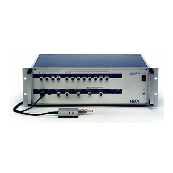
2. Description of the Hardware The hardware components of the EPC9 patch-clamp system consist of the head stage (or probe), the amplifier main unit with the integrated ITC-16 interface board, and the computer system. Specific information about the hardware installation is given below in Chapter 3. -
Page 11: Main Unit
“Scale.epc” and “CFast.epc”. Unlike conventional amplifiers, hardware calibration of the EPC9 can also be performed by the user if necessary (see section Calibrating the EPC 9 on page 16). Note: Calibration parameters are unique to each amplifier and head stage combination. - Page 12 Chassis Gnd: The chassis is connected to the ground line of the power cord, as is typical of most instruments. The Signal Ground is kept separate from the chassis to avoid ground loops, but is connected to it through a 10 Ω resistor. Test Input: This input is used for the Test mode.
- Page 13 Clipping: This LED lights whenever an amplifier saturates in the current monitor pathway. The indicator is important in voltage-clamp experiments where capacitive artifacts will be subtracted in a computer; the subtraction will work well only as long as no saturation occurs, and this indicator serves as a simple monitor of this condition.
- Page 14 Rear-panel connectors: Three 40-pin connectors and an analog trigger input allow connection of the EPC9 to other devices: • Computer-Interface: This is the connection to the Mac-23, AT-16, PCI-16, or PCI-18 board in the host computer, that allows the computer to communicate with the EPC9.
-
Page 15: Epc 9 Double And Triple
EPC 9 Double and Triple The EPC9 Double and Triple contain two and three independent EPC9-amplifiers in one case, respectively. All amplifiers share a single ITC-16 AD/DA-board. The ITC-16 board provides 4 DA-channels which are sufficient to allow simultaneous stimulation of every individual amplifier. The 8 available AD-channels can independently read all voltage- and current-outputs of the individual amplifiers. -
Page 16: Installation
HEKA. However, it is advisable to recalibrate the EPC9 twice a year or whenever the frequency response of the amplifier is not accurate or offset currents become noticeable. - Page 17 Then you are instructed to remove anything from the probe and shield its input: You can use the metallic cap that came with your EPC9 and put it on the BNC connector of the probe to shield it. Please make sure that really nothing except the metallic cap is connected to the probe (the red and the black pin jack should be free) and that no BNC cables are connected to the inputs and outputs of the EPC9 ! At the end of the calibration, E9SCREEN will let you know, whether the calibration...
-
Page 18: Creating The C-Fast Lookup Table
If you have an EPC9 Double or Triple, you should proceed to calibrate the second and Record 2. Amplifier Noise third amplifier as well. From the amplifier pop-up menu, choose 2. Amplifier or 3. SET-UP ON-CELL WHOLE-CELL Amplifier and repeat the steps listed above. After having calibrated the amplifier (all amplifiers in case of an EPC9 Double or Triple), you should also create a new C-fast lookup table for each amplifier as stated in the next section. -
Page 19: Verifying And Testing The Epc
4. Verifying and Testing the EPC 9 Testing the EPC9 with the Model Circuit The following tutorial will guide you through most of the basic and some of the unique and more sophisticated features of the EPC9 amplifier. At the same time it allows you to check, whether the amplifier is functioning properly. -
Page 20: Step 1: Applying The Test Pulse
If E9SCREEN is not running yet, start the program which is located in the E9SCREEN folder inside the HEKA folder. Windows users might alternatively use the button to launch E9SCREEN from Start . - Page 21 EPC9 Patch-Clamp Amplifier, v8.3 Record 1. Amplifier Noise 0.00 A empty empty empty empty Reset SET-UP ON-CELL WHOLE-CELL Hz/MΩ Rmem V-memb + / - Gain Clip Sound 100 % 0.0 mV 5.0 mV/pA Volume Imon2 Sound Help Last V-memb Auto Track 0.0 mV -2.8 mV...
- Page 22 following built in macro that resets the amplifier, creates a rectangular test pulse, sets the gain of the amplifier to 5 mV/pA and then performs an automatic compensation of the voltage offsets: 1 : SET-UP Reset: ; reset the amplifier PulseAmp: 5.0mV ;...
-
Page 23: Step 2: "On-Cell" Voltage-Clamp Recording
Step 2: ”On-Cell” Voltage-Clamp Recording Now move the switch of the model circuit to the center position which leaves only a capacitance of about 6 pF connected. This simulates a Giga-Ohm seal and the C-fast controls can be used to cancel the capacitive spikes resulting from the stimulus test pulse. -
Page 24: Step 3: "Whole-Cell" Voltage-Clamp Recording
C-fast – using the model circuit it is not very critical to misadjust -fast. Continue adjusting C-fast and -fast unless you see an almost flat line in the oscilloscope (red line). This should be the case at a around 6 pF (2). Instead of compensating C-fast ”by hand”... - Page 25 values – again by clicking and dragging the mouse upwards. Since there are two variables to adjust this is more difficult than the C-fast compensation. However, with some praxis you will get a better feeling for these parameters and how they effect the recording.
-
Page 26: Step 4: "Whole-Cell" Current-Clamp Recording
3 : WHOLE-CELL Invert: TRUE Gain: ; set gain to 20 mV/pA CSlow: 30.00pF ; set C-Slow value to 30 pF RSeries: 10.0MO ; set R-Series value to 10 MOhm AutoCSlow: ; automatic C-slow compensation AutoCSlow: ; repeat compensation SoundOn: TRUE ;... - Page 27 labeled CC Fast Speed and then open the oscilloscope again (6). Now, you will see a much slower signal (red line in the oscilloscope). Please note, that the fast current clamp mode is very sensitive to misadjustment of the C-fast setting. Especially overcompensation causes the signal to oscillate.
- Page 28 The following figure shows a recorded action potential (from H. Taschenberger & H. von Germsdorff): Presynaptic Action Potential of the Calyx of Held in the Rat Brainstem 0 mV 20 mV 250 µs -60 mV fast current clamp normal current clamp Testing the EPC9 EPC9 Manual...
-
Page 29: Step 5: Measuring The Noise Of The Amplifier
Step 5: Measuring the Noise of the Amplifier Now let us come to the final section of the tutorial and check the intrinsic noise of the amplifier. E9SCREEN has a built in feature that allows you to easily and quickly check the noise of your amplifier and to minimize your setup’s noise, e.g., by optimizing the grounding of the setup. - Page 30 The action of the internal filters on the background noise level and the temporal response can be observed by changing Filter 1 and Filter 2. An improved signal-to- noise ratio should be apparent when the Gain is increased to 50 mV/pA or greater (which selects the 50 GΩ...
-
Page 31: Making A "Full Test
If you ever encounter any hardware problems that can not be solved by simply re- calibrating the amplifier (see Calibrating the EPC 9 on page 16) you can run the Full Test in E9SCREEN. This feature is a diagnostic tool that allows us at HEKA Elektronik to make some conclusions about possible defects of the amplifier. - Page 32 VMON1 IMON1 VMON2 IMON2 VMON3 IMON3 STIM1 STIM2 STIM3 TEST CURRENT MONITOR EXTERNAL VOLTAGE TEST FILTER 1 FILTER 2 PROBE STIM.INPUT MONITOR INPUT The following table shows you the combinations for the different amplifiers: EPC9, EPC9 Double, and Triple. The EPC9 Triple has only one free AD input left (ADC-6), the remaing channels are internally connected with the corresponding channels of the amplifier.
- Page 33 - Fax: +49 (0) 6325 955 350 Important note: Please, remind: if you get a message like this, please, contact HEKA first and supply us the error protocol before sending the amplifier in. You might save yourself valuable time and effort!
-
Page 34: Measuring The Frequency Response
Measuring the Frequency Response The Test mode allows one to easily check the basic current-measuring circuitry of the EPC9. Select Test from the Mode list, connect a function generator or stimulator to Test Input, and connect the right-hand Current Monitor Output (Filter 2) to an oscilloscope. -
Page 35: E9Screen Software
5. E9SCREEN Software The E9Screen software provides the control and the graphical representation of the EPC9 amplifier by a “virtual panel” with “buttons”. Signal display is provided by an oscilloscope-like display. In addition, there is a Notebook window and drop-down menus with options for the calibration procedures. - Page 36 switching, E9Screen updates all parameters to show the state of the selected amplifier. The state of each amplifier is independent of the settings of the other amplifiers. Macros: Macro buttons allow to record and Record empty empty play back a sequence of actions, such as SET-UP ON-CELL WHOLE-CELL...
- Page 37 Note: There is a limit of 50 actions per macro. To abort recording of a macro, click again on “Record” and the just recorded sequence will be lost. Noise: The rms noise is continuously measured and updated when the noise mode is selected with the button Noise.
- Page 38 Medium High Feedback Resistor 5 MΩ 500 MΩ 50 GΩ Gain 0.005-0.002 0.5-20 50-2000 ± 2 µA ± 20 nA ± 200 pA Bandwidth 100 kHz 100 kHz 60 kHz C-slow Ranges 30 • 100 • 1000 30 • 100 • 1000 30 •...
- Page 39 AD-Channel: The oscilloscope can display the following: • F2-Ext - External Stim. Input filtered by Filter 2 • Imon-1 - Current monitor 1 • Imon-2 - Current monitor 2 • Vmon - Voltage monitor output • AD 0…5 - Any of the other AD channels. The F2-Ext setting allows you to use Filter 2 as a general-purpose variable filter.
- Page 40 Out Out Recording Modes), before the actual zeroing operation is performed. Auto-V does this automatically and leaves V-membrane at that value. Note: is not changed by the Reset function. Track: This option implements a Search Mode (see Chapter 6. Operating Modes on page 58), which is essentially a repetitive Auto-V procedure at a holding potential of 0 mV.
- Page 41 Mode: Sets the Recording Mode (in the above example it is Voltage Clamp). For details on the various recording modes see Chapter 6. Operating Modes on page 54. • Test - Sets the Test mode. • VC - Sets the Voltage Clamp mode. •...
- Page 42 kHz in 0.1 kHz steps (guaranteed accuracy 0.5-15 kHz). Two filter characteristics can be selected from the pop-up menu: • Bessel • Butterworth The -3 dB point is given in both cases. Bessel is the best characteristic for general use; the Butterworth response rolls off more rapidly with frequency and is mainly useful for power spectral analysis.
- Page 43 <>: This will select both amplitude and time constant of C-fast. Values for each may be changed manually depending on whether the mouse is moved horizontally or vertically. Auto C-fast: Selection of this button performs an automatic compensation of C-fast τ...
- Page 44 to make the time constant R-series * C-slow greater than 5 µs to prevent oscillations. The C-slow value may be adjusted manually by dragging the mouse, or typing, or automatically by selecting the Auto function. Auto-compensation will adjust C-slow as well as R-series. R-series: Adjusts the resistance in series with the slow capacitance (range: 0.1 MΩ...
- Page 45 Delay: This determines how many seconds to wait before the next auto- compensation is started. With short delays (e.g., 1 ms), membrane capacitance will be tracked at rates of >10 Hz (depending on the Macintosh model). Note: You can increase the rate of Cap. Track (about two-fold) when closing the Oscilloscope.
-
Page 46: Hidden Controls
Usually a setting of 20 µs is sufficient, unless very fast currents such as Na currents are studied. External: The external Stim. Input is scaled by an editable factor (range: ±0-10x), to allow for different external stimulators. It is strongly recommended to set External to Off (i.e., equal to zero), if no external stimulator is connected to the Stim. - Page 47 Sound Settings: Sensitivity (Hz/MΩ) and volume Hz/MΩ Rmem (in %) of the sound encoding of R-membrane can be Sound 100 % specified here. To enable the sound option press the Volume Sound button. CC Fast Speed : Clicking on this button enables the fast current- clamp mode (only version “C”...
-
Page 48: Notebook Window
Notebook Window The Notebook window is used to display printed output of the program, such as error messages or information about calibration and diagnostic data, for example. The content of the Notebook can be stored in a memory file; its maximal size can be to be specified in the drop-down menu Notebook. -
Page 49: Edit Menu
Edit Menu The Edit menu is not used by E9Screen except for text manipulation of the Notebook content. All entries are normally disabled unless the Notebook is selected. The menu entries conform to the standard Macintosh functions. The Cut, Copy, and Paste commands copy the text selection to and from the clipboard. -
Page 50: Epc9 Menu
EPC9 Menu Iconize: Collapses the window and leaves the title bar of the window on the desktop. Dialog: Selects a submenu for the Amplifier dialog window. The following functions are available: • Load…: Loads a saved dialog window. • Save…: Saves a modified dialog window. •... - Page 51 Log Tracking: Writes the updated values of C-slow, G-series, and G-leak to the Notebook when capacitance tracking is on. Output Cap. Track: Outputs the values of C-slow and G-series as analog voltages to DA 0 and DA 1, respectively. Quick C-slow: Selects an alternate procedure for Auto C-slow compensation. It speeds up repetitive compensations, as it does not switch the gain, filter settings, etc.
-
Page 52: Notebook Menu
Notebook Menu Save: Saves the Notebook under its default name: “Notebook_Date”. Save as…: Asks for a filename before saving. Merge...: Appends the present Notebook to an existing one. Print…: Output content of Notebook to a printer. some text selected (i.e. highlighted), only that text selection is printed. -
Page 53: Calibrate Menu
Full Test: Performs a hardware test. This generates a list of diagnostic values. This may be used to inform the manufacturer (HEKA) about the condition of the EPC9. If you have any doubts about your EPC9 test, please contact HEKA to find out whether or not it needs to be serviced. -
Page 54: Operating Modes
6. Operating Modes The EPC9 is fundamentally an instrument for measuring small electrical currents. It uses a current-to-voltage (I-V) converter circuit to convert the currents to an analog voltage, which is then made available at the current monitor outputs for display or recording. - Page 55 viewport now becomes an I-membrane display and may be used to inject a steady command current through the action of the feedback amplifier. In E9Screen, the membrane potential is shown in the I-mon display; in Pulse, the I-mon display is converted to V-mon).
- Page 56 The main problem with current-clamp settings is stability, as the feedback loop will oscillate when C-fast is set to its true value; the loop expects at least a small amount of uncompensated C-fast for a phase lead at high frequencies. The EPC9 software will assume that the user has compensated C-fast correctly, and in the process of switching to current-clamp mode, it will set its value slightly lower (0.5 pF) to optimize the speed of recording.
-
Page 57: Test Mode
stable with pipette and series resistance down to 1 MΩ. The large capacitance will however produce an extra load on small cells, slowing the time course of membrane potential changes. Test Mode This mode is only available in E9Sreen. It is very much like the voltage-clamp mode (see figure below) except that the Test Integrator signal is used to inject small test currents into the I-V converter input. -
Page 58: Search Mode
Search Mode In the EPC9, this mode has no special analog circuitry. Rather, it is a software emulation of the traditional search mode found in the EPC7 amplifier. The EPC7 accomplished the search mode by analog circuitry in order to ease the adjustment of the zero-current potential V . -
Page 59: Compensation Procedures
7. Compensation Procedures Series Resistance Compensation In whole-cell voltage-clamp recording, the membrane potential of the cell is controlled by the potential applied to the pipette electrode. This control of potential is not complete, but depends on the size of the access resistance between the pipette and the cell interior, and on the size of the currents that must flow through this resistance. - Page 60 The EPC9 incorporates additional circuitry to allow capacitance transient cancellation to occur while R -compensation is in use (see Sigworth, Chapter 4 in Single Channel Recording). This is shown as the prediction pathway in the figure below, and it accelerates the charging of the membrane capacitance by imposing large, transient voltages on the pipette when step changes are commanded (this is sometimes called “supercharging”).
- Page 61 consists of adjusting C-slow and R-series to cancel the transient currents due to the cell membrane capacitance. Once this has been done, the relative amount of R compensation can then be selected with the %-comp control. Theoretically, it is desirable to compensate as much of the series resistance as possible.
-
Page 62: Capacitance Compensation
The table gives maximum α values (i.e., %-comp u (µs) c (µs) τ c settings) and the resulting values in the 2 µs 0.85 setting for some values of the uncompensated time constant τ u . At the 10 µs setting, full 90% com- 0.80 pensation may be used without overshoot for time 0.75... -
Page 63: Offset Compensation
alternatingly to arrive at settings for which the remaining transient is minimal. Settings for C-fast are left at their respective values whenever an Auto C-slow is performed and vice versa. This way, a combined fit can be obtained by alternatingly executing Auto C-slow and Auto C-fast. - Page 64 It is standard practice to take care of the fixed offsets by performing a reference measurement at the beginning of an experiment. Thereby an adjustable amplifier offset is set for zero pipette current. Thereafter the command potential of the amplifier (displayed as V-membrane) will be equal in magnitude to the membrane potential if no changes in offset potentials occur.
- Page 65 An analysis of the underlying offset problem and justification for the procedures can be found in Neher (1995). The rule for calculating the Offset Sum (LJ) is to form the sum of all changes in offsets which occur between the reference measurement and the test measurement. The polarity of a given offset voltage should be taken as viewed from the amplifier input (positive, if positive side of the voltage source is closer to the input).
- Page 66 Example 2: An outside-out or whole-cell measurement with KCl-based internal solution in the pipette. LJ should be set to 3 mV (see table) in order to correct for the disappearance of a liquid junction potential between the KCl containing pipette and the NaCl-based bath solution.
-
Page 67: Patch-Clamp Setup
8. Patch-Clamp Setup Mounting the Probe For low-noise recording, the pipette holder must be attached directly to the EPC9 probe. Although the probe amplifier can tolerate the additional capacitance of a short connecting cable without instability or oscillations, we find that the dielectric and electrostrictive properties of coaxial cables introduce excessive noise. -
Page 68: External Shielding
well-grounded setup, the microscope can provide most of the shielding. Make sure there is electrical continuity between the various parts of the microscope, especially between the microscope frame and the stage and condenser, which are usually the large parts nearest the pipette. Electrically floating surfaces can act as “antennas”, picking up line-frequency signals and coupling them to the pipette. -
Page 69: Bath Electrode
recordings, the unshielded holder is strongly recommended. The difference in background noise level between the two holder types is roughly a factor of two. The unshielded holder is made from polycarbonate, having low dielectric loss. If you make your own holder, you should give some thought to the choice of materials. The insulating parts of the holder should be of a low-loss material, and should have a hydrophobic surface to prevent the formation of conducting water films. - Page 70 Ag-AgCl wire agar to probe GND The body of the electrode is a 1 ml plastic syringe body that has been heated and pulled to form a small, bent tip. The electrode proper is a chlorided Ag wire that is first inserted with the plunger into the fluid-filled body;...
-
Page 71: Patch-Pipettes
9. Patch-Pipettes Glass Capillaries Procedures for fabricating pipettes are presented in some detail in the paper by Hamill et al. We will summarize the procedure and present some tips that we have found helpful. The main steps in pipette fabrication are to form a smooth tip on the pipette (to allow seals to be formed without damaging the cell membrane) and to coat the pipette with a suitable insulating coating to reduce the background noise. -
Page 72: Pulling
Hard-glass pipettes often have a narrow shank after pulling and consequently a higher resistance. Hard glasses tend to have better noise and relaxation properties, however: the important parameter here is the dielectric loss parameter, which describes the AC conductivity of the glass. Although the DC conductivity of most glasses is very low, soft glasses in particular have a conductivity around 1 kHz;... -
Page 73: Heat Polishing
Heat Polishing Heat polishing is used to smooth the edges of the pipette tip and remove any contaminants left on the tip from coating. It is done in a microforge or similar setup in which the pipette tip can be observed at a magnification of 400-800x. The heat source is typically a platinum or platinum-iridium wire;... - Page 74 check the noise level of the empty holder using the Noise Test function; if it increases, solution has probably spilled inside the holder; in this case the holder should be cleaned again and dried thoroughly. Patch-Pipettes EPC9 Manual...
-
Page 75: Using The Patch Clamp
10. Using the Patch Clamp We give here a brief description of the techniques for establishing a seal and recording from a membrane patch or from an entire small cell. Forming a Seal Initial Setup The object is to apply voltage pulses to the pipette and observe the Current Monitor signal on an oscilloscope to monitor the pipette resistance. -
Page 76: Forming A Gigaseal
example: 1. a bubble in the pipette; 2. faulty connection to the probe input; 3. bath electrode not connected. There is invariably a small offset potential between the pipette and bath electrodes. The V control is designed to provide a bucking potential to cancel this offset. With the pipette in the bath, select the Auto-V button. -
Page 77: Whole-Cell Recording
If you are applying voltage pulses to the patch membrane, you probably will want to subtract control traces from the traces containing the channels of interest in order to remove the capacitive transients. Nevertheless, it is important to try to cancel the capacitive transients as well as you can in order to avoid saturating any amplifiers, the recording medium or the AD converter. -
Page 78: Capacitive Transient Cancellation
the current level. Additional suction sometimes lowers the access resistance, causing the capacitive transients to become larger in amplitude but shorter. Low values of the access (series) resistance are desirable and, when R -compensation is in use, it is important that the resistance be stable as well. A high level of Ca buffering capacity in the pipette solution (e.g., with 10 mM EGTA) helps prevent spontaneous increases in the access resistance due to partial resealing of the patch membrane. -
Page 79: Current-Clamp Recording
provide the necessary rapid compensation; however, the slower settings will provide compensation that is less prone to high-frequency oscillations from misadjustment of τ u the controls. How much compensation you can apply is also determined by tu. If is larger than about 100 µs, you can use any degree up to the maximum of 90% compensation without serious overshoot or ringing in the voltage-clamp response. -
Page 80: Low-Noise Recording
11. Low-Noise Recording The EPC9 amplifier has a particularly low background noise level. The noise level is in fact low enough that in most experimental situations it can be neglected in view of other background noise sources that make larger contributions to the total. As we consider these other sources, first let us make it clear that in this section we are concerned with random noise, which is fundamentally due to the thermal motion of electrons and ions;... - Page 81 holder, and the combination of pipette immersion and patch noise. The table below shows the relative contributions calculated in this way for the “optimum” situation just described. Noise Source Contribution rms Current The contributions to the variance from the three sources are seen to Amplifier 35 % 95 fA...
- Page 82 the pipette to remove any spilled solution, fingerprints, etc. before inserting it into the holder. It might also help to treat the inside of the pipette to prevent the formation of a film, for example, by shooting some dimethyl-dichlorosilane vapor (caution: nasty stuff!) into the back of the pipette before or after filling it.
-
Page 83: Appendix I: Controlling E9Screen
Appendix I: Controlling E9SCREEN Communication between E9Screen and other Programs E9Screen has two functions which enable a second acquisition program to share the AD/DA-board. This allows the E9Screen to control the EPC9, while the second program can use the AD/DA-board for acquisition: 1. - Page 84 • In voltage clamp mode (VC-mode): VHOLD: -0.080; IGAIN: 1.0000E+09 0 [V] 1.0000E+01 1 [-] 1.0000E+00 2 [-] 1.0000E+00 3 [-] 1.0000E+00 4 [-] 1.0000E+00 5 [-] 1.0000E+00 6 [A] 1.0000E+09 7 [A] 1.0000E+09 • In current clamp mode (CC-mode): IHOLD: 1.0000E-10;...
-
Page 85: Controlling The Epc9 From Another Program
• AD-7 is the I-mon 1 input, i.e., the current input after filter 1. To read V-mon, one has to connect the corresponding V-mon output of the EPC9 to any suitable AD-input channel (but not 6 or 7). The user can now switch between two programs. - Page 86 • Every command plus the required parameters must be in one text line, i.e., terminated by a “CR” character code (any following linefeed character will be ignored). • E9Screen writes the responses to the “response” file. In the first line of that file, E9Screen writes the “command index”.
-
Page 87: Error Messages
When the user program wants to issue new commands, it writes a new “command index” and the new commands to the “command” file, then continues with step 5. Here is an example of such a command file: 1. line: "1234" 2. - Page 88 GetCFastError GetCFastTau GetClipping GetCSlow GetCSlowError GetCSlowRange GetCurrentGain get gain in Ohms (i.e., V/A) GetE9SBoard GetE9SerialNo GetF2Butterworth GetF2Frequency GetFilter1 GetGLeak GetGSeries GetIpipette GetLastVHold GetMode GetRmembrane GetRsFraction GetRsMode GetRsValue GetStimFilterOn GetVCStimScale GetVersion GetVHold GetVLiquidJunction GetVmonitor GetVpOffset “Set” operations: They have no or one parameter and do not return a response. SetAdcChannel integer: 0 to 12 ->...
- Page 89 acknowledged (re-synchronize command index) syntax: "acknowledged" no parameters no response ADRead syntax: "ADRead AD-channel" AD-channel: integer 0 to 7 returns a real (read AD-value in Volts) ADRelease syntax: "ADRelease" no parameters returns string "ADReleased" ADReserve syntax: "ADReserve" no parameters returns: if it could reserve the AD-board: string "ADReserved"...
- Page 90 cursor keys: 3 -> KeyCursorUp 4 -> KeyCursorDown 5 -> KeyCursorLeft 6 -> KeyCursorRight numeric keypad: 7 -> 0 (zero) on numeric keypad 8 -> 1 on numeric keypad 9 -> 2 on numeric keypad 10 -> 3 on numeric keypad 11 ->...
-
Page 91: Notes To Programmers
Notes to Programmers If one uses the EPC9 acquisition board to acquire data in a user program, one has to be very aware that the EPC9 is controlled through its AD/DA-board as well. Thus, every time E9Screen has to talk to the EPC9, it will unconditionally make use of the AD/DA- board. - Page 92 6. E9Screen writes responses to the message files in the following situations: - On starting "batch" processing, it messages "Started". - Responding to a "Get", "Query", or "Terminate" instruction. - When an error occurred while scanning the message file. Controlling E9Screen EPC9 Installation...
-
Page 93: Sample Program
Sample program The listing below is an excerpt from the program used to test the E9Screen communication protocol. It demonstrates the functions needed to write an own program to control the EPC9 through the E9Screen program. The code is written in Modula-2. The code can be easily understood also by readers familiar with BASIC, PASCAL, C, C++, or FORTRAN. - Page 94 ( NOT IOBytes.SetLength( CommandFile, 0 ) ) OR ( NOT IOText.Write( CommandFile, Count, ADR( Work ) ) ) THEN WriteError( 'Writing negative signature' ); RETURN FALSE; END; (* IF *) Count := Strings.Length( Text ); (* Second, we write the command text to the second (and following) line.
- Page 95 END; (* IF *) IF NOT IOText.Open( MessageName, IOFiles.Read + IOFiles.Shared, MessageFile ) THEN IF IOFiles.GetError() <> IOFiles.FileNotFound THEN WriteError( 'Opening message file' ); END; (* IF *) RETURN FALSE; END; (* IF *) LastSignature := -1; RETURN TRUE; END OpenMessageFile; PROCEDURE PollForCommands;...
- Page 96 RETURN; END; (* IF *) TermIO.WriteString( 'response: [' ); TermIO.WriteInt( NewSignature, 0 ); TermIO.WriteString( '] ' ); Count := HIGH( InputString ); IF IOText.Read( MessageFile, Count, ADR( InputString ) ) THEN TermIO.WriteLine( InputString ); ELSE If the "response" text is empty, then the command has been sucessfully processed! TermIO.WriteLine( 'done.' );...
- Page 97 IF NOT IOText.Open( CommandName, IOFiles.Create + IOFiles.Write + IOFiles.Shared, CommandFile ) THEN WriteError( 'Opening command file' ); RETURN FALSE; END; (* IF *) Signature := 1; RETURN TRUE; END Startup; PROCEDURE InitModule; BEGIN CommandFile.IsOpen := FALSE; MessageFile.IsOpen := FALSE; Signature := 1;...
-
Page 98: Appendix Ii: Technical Data
Appendix II: Technical Data Digital I/O Connector EPC9 The pin assignment of the 40-pin connector on the EPC9 is: Pin number EPC9 Pin number EPC9 IN-0 OUT-14 Not connected OUT-15 IN-2 IN-10 IN-3 IN-11 IN-4 IN-12 IN-5 IN-13 IN-6 IN-14 IN-7 IN-9 IN-1... -
Page 99: Epc9 Double And Triple
PIN 1 of the 40-pin connector is labled with a small arrow: PIN 39 PIN 1 PIN 40 PIN 2 EPC9 Double and Triple The pin assignment of the 40-pin connector on the EPC9 Double and Triple is: Pin number EPC9 Pin number EPC9... - Page 100 The current drivers can sink up to 1 A current. The maximal power supply voltage should not exceed 24V. EPC 9 Double External Power IN +5 .. 24V TRIGGER Valve Power supply OPTO Ground IN Ground Arrangement for current driven devices...
-
Page 101: Index
Index Auto CFast Hotline Auto CSlow I-mon display Auto-V0 Macros Calibrate ON-CELL Calibrate Menu SET-UP Calibration WHOLE-CELL Cap Track Make CFast 16, 18 CC Fast Speed Model Circuit CC mode Noise CFast Compensation Noise Button C-Fast Lookup Table On-Cell Recording Rmem display Creating CSlow...
Need help?
Do you have a question about the EPC 9 and is the answer not in the manual?
Questions and answers