
Related Manuals for INOXPA ASPIR A-50


Summary of Contents for INOXPA ASPIR A-50
- Page 1 INSTALLATION, SERVICE AND, MAINTENANCE INSTRUCTIONS ASPIR INOXPA, S.A. c/Telers, 54 Aptdo. 174 E-17820 Banyoles Girona (Spain) Tel. : (34) 972 - 57 52 00 Fax. : (34) 972 - 57 55 02 Email: inoxpa@inoxpa.com www.inoxpa.com...
- Page 2 Denomination Type Manufacturing year Comply with the pertinent disposition, in the execution supplied by INOXPA, S.A. for the incorporation in a machine or installation, or for the assembly with other machines as a subunit of other higher order machine. Harmonized norms used, particularly:...
-
Page 3: Instructions Manual
The first thing to do when the pump is received is to check it and ensure that the contents conform to the shipping voucher. INOXPA inspects all equipment prior to shipment, but it cannot guarantee that the merchandise reaches the user intact. - Page 4 B. Technical principles. Quantity Symbol Unit µ Dinamic viscosity mPa.s (=cP=Centipoise) with ρ=specific weight V=µ/ρ [Kg/dm and V = kinematic viscosity Kinematic viscosity /s] = cSt = Centistoke Only the dynamic viscosity is used in this manual. [bar] ∆p Pressure [bar] - differential pressure [bar] - maximum pressure at discharge mouth (design pressure) Unless otherwise indicated, in this manual pressure is understood to be relative pressure.
-
Page 5: Warranty
The machine's safety is only ensured if it is used properly in accordance with the instructions given in this manual. The limits for values specified in the data sheet cannot be exceeded under any circumstances. Any change in operating conditions can only be done with the prior written consent of INOXPA. WARRANTY. -
Page 6: Table Of Contents
1. Introduction Check the shipment ......................1.1 Instructions manual ......................1.1 Start-up instructions ......................1.1 Maintenance ........................1.1 Operating principles ......................1.1 Warranty ..........................1.3 INOXPA Service .......................1.3 2. Table of Contents 3. General Information Description ........................3.1 Principle of operation ......................3.1 Noise ..........................3.1 Application ........................3.1 Hygiene ..........................3.1 Materials used in construction ...................3.1... - Page 7 9. Technical Specifications Technical specifications .....................9.1 Materials ..........................9.1 ASPIR MR pump dimensions ....................9.2 ASPIR MB pump dimensions.....................9.3 ASPIR pump motor coupling dimensions .................9.4 ASPIR pump with flameproof motor dimensions .............9.5 ASPIR MR pump .......................9.6 Parts list ASPIR MR pump ....................9.7 10.
-
Page 8: General Information
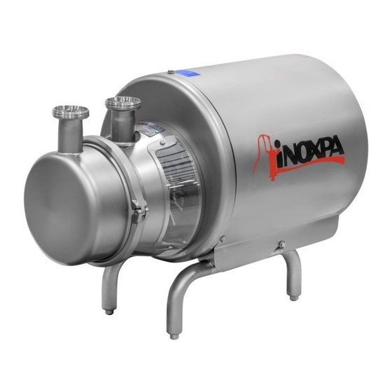
3. General Information DESCRIPTION. The salf-priming pumps in the ASPIR series are manufactured using AISI-316 stainless steel die-pressed steel plate and steel casting with an electro-polished finish. The ASPIR pump has a compact construction, monoblock, vertical intake and discharge, and sanitary-type connections. The impeller is of open design and made of one single piece. -
Page 9: Fields Of Application
When the pump is used in a pumping unit or in an environment for which the pump has not been designed, the operator and the material may be exposed to hazard. Consult with INOXPA in case of doubt prior to use. -
Page 10: Shaft Sealing
Table 3.3: field of application ASPIR 50 Hz 60 Hz Maximum flow rate 56 m 50 m Maximum differential pressure 6 bars 5,5 bars Maximum suction pressure 4 bars 4 bars Maximum temperature 120 °C 120 °C Maximum recommended viscosity 250 mPa.s. -
Page 11: Installation
4. Installation GENERAL CONSIDERATIONS. This manual provides basic instructions which should be taken into account when proceeding to install the pump. It is of utmost importance that the shop foreman read this manual before assembly. The instructions include pertinent information which will enable you to install your pump correctly. The manual also contains important instructions for preventing possible accidents and serious damage which could occur prior to start up and during the installation : •... -
Page 12: Location
It is very important to be able to gain access to the pump connecting device (including when it is operating). Outdoor installation. The ASPIR pump can only be installed out of doors if there is a roof covering or the pump is shrouded. Consult with INOXPA prior to installation. -
Page 13: Direction Of Rotation
Protection of the motor against overloads. In order to protect the motor from overloads and short circuits, the use of thermal or magnetic relays is recommended. Adjust these relays to maximum rated current values as indicated on the data plate of the motor. Connection. - Page 14 Figure 4.3: Suction and discharge pipe Pipes. Use pipes with a diameter which is equal to or greater than that of the pump's connections. If the liquid to be pumped is viscous, the loss of head from the suction and discharge pipes can increase considerably. Other pipe components such as valves, elbows, filters and foot valves, can also cause a loss of head.
- Page 15 Filters. Foreign particles can seriously damage the pump. Avoid the entry of these particles by installing a filter. When selecting a filter, bear in mind the diameter of the screen openings so that loss of head will be minimal. The filter diameter should be three times greater than that of the suction pipe.
-
Page 16: Start-Up
5. Start-up GENERAL CONSIDERATIONS. The pump can be started up so long as the instructions given in chapter 4 ("Installation") have been followed. Prior to start-up, the persons responsible for the operation must be duly informed of the pump’s operation and the safety instructions. -
Page 17: Maintenance
INOXPA does not assume responsibility for accidents and damage which might occur as a result of any failure to comply with the instructions indicated herein. -
Page 18: Maintenance
Maintenance work on electrical installations can only be done by qualified personnel and only when the power supply has been cut off. Carefully follow national safety regulations. Also abide by the regulations referred to above if you are working while the power supply is still connected. Also abide by the regulations referred to above if you are working while the power supply is still connected. -
Page 19: Operating Problems
7. Operating Problems Problems Probable Causes Overloading of motor. 7, 8, 12 Insufficient flow rate or pressure in pump. 1, 2, 4, 5, 6, 7, 8 No pressure on the discharge side. 2, 3, 6, 16 Irregular discharge flow rate / pressure. 1, 2, 4, 5, 6, 8 Noise and vibrations. -
Page 20: Disassembly And Assembly
Incorrect assembly or disassembly may cause damage in the pump's operation and lead to high repair costs and a long period of down-time. INOXPA is not responsible for accidents or damages caused by a failure to comply with the instructions in this manual. -
Page 21: Impeller
IMPULSION COVER. • Close the suction and discharge valve. ATTENTION! The liquid can spill out when the impulsion cover and the venturi fox is removed. • Remove the clamp (15). • Check to see that the O-ring (80A) is still in good condition. •... - Page 22 In order to replace the motor (93), follow the indications as given in the foregoing sections disassemblies. • Remove the splash ring (82). • Loosen the studs (55) and take the shaft (05) out. • Remove the screws (50) and take out the shroud (14); only on the MR version. •...
-
Page 23: Technical Specifications
9. Technical Specifications. TECHNICAL SPECIFICATIONS. Motor acr. IEC shaft sealing impeller TYPE 50 Hz [kW] diameter 1450 min Frame seal diameter A-50 0.75 A-80 A-150 A-200 MATERIALS. Parts in contact with the liquid Part Item Material Material n. Aspiration casing CF - 8M (1.4408) Impulsion cover... -
Page 24: Aspir Mr Pump Dimensions
ASPIR MR pump dimensions. Motor ∅ TYPE DNa DNi A-50 0.75 1½” 1½” A-80 1½” 1½” A-150 2” 2” A-200 3” 3” Dimensions with connections DIN 11851 9. Aspir Technical Specifications 9.2 Ed. 5.5/05... -
Page 25: Aspir Mb Pump Dimensions
ASPIR MB pump dimensions. Motor TYPE DNa DNi A-50 0.75 1½” 1½” A-80 1½” 1½” A-150 2” 2” A-200 3” 3” Dimensions with connections DIN 11851 Ed. 5.5/05 9. Aspir Technical Specifications 9.3... -
Page 26: Aspir Pump Motor Coupling Dimensions
ASPIR pump motor coupling dimensions. Motor TYPE frame A-50 A-80 100/112 A-150 100/112 A-200 9. Aspir Technical Specifications 9.4 Ed. 5.5/05... -
Page 27: Aspir Pump With Flameproof Motor Dimensions
ASPIR pump with flameproof motor dimensions. Motor TYPE DNa DNi A-50 1½” 1½” A-80 1½” 1½” A-150 2” 2” A-200 3” 3” Dimensions according to flameproof motor CEMP. Ed. 5.5/05 9. Aspir Technical Specifications 9.5... -
Page 28: Aspir Mr Pump
ASPIR MR pump. 9. Aspir Technical Specifications 9.6 Ed. 5.5/05... - Page 29 Parts list ASPIR MR. Position Quantity Description Material Aspiration casing CF - 8M Impulsion cover AISI - 316 Impeller CF - 8M Lantern CF - 8 Shaft AISI - 316 Legs AISI - 304 Adjustable leg AISI - 304 Mechanical seal –rotating part- Mechanical seal –stationary part- Shroud AISI - 304...
-
Page 30: Cleaning And Disinfection
10. Cleaning and Disinfection GENERAL CONSIDERATIONS. Cleaning and disinfection of the installations is necessary and mandatory on completing any manufacturing process in the food industry. The use of an installation which is NOT cleaned or disinfected can cause contamination of the products. The cleaning cycles as well as the chemical products and procedures used will vary depending on the product and the manufacturing process. -
Page 31: Safety In Cleaning And Disinfection
SAFETY IN CLEANING AND DISINFECTION. Manual cleaning. • Disconnect the motor starting system before cleaning the pump. • Provide cleaning personnel with the most appropriate protective equipment -clothing, footwear, safety glasses. • Do not use toxic or inflammable solvents for cleaning the pump. •...
Need help?
Do you have a question about the ASPIR A-50 and is the answer not in the manual?
Questions and answers