
Related Manuals for Danfoss OPTYMA Control AK-RC 101


Summary of Contents for Danfoss OPTYMA Control AK-RC 101
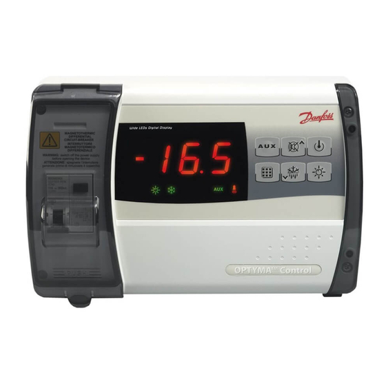
- Page 1 MAKING MODERN LIVING POSSIBLE OPTYMA Control Single-phase AK-RC 101 Operation and Maintenance Guide...
-
Page 2: Table Of Contents
Pump-down function .................................. 13 Password function ..................................13 Alarm relay ......................................14 Trouble shooting / Alarm list ..............................15 Connection diagrams ..................................16 Parts list ........................................ 18 Ordering ....................................... 19 RS8FD402 © Danfoss A/S 2014/11 OPTYMA Control single-phase AK-RC 101... -
Page 3: General
ADAP-KOOL® system unit. access to the automatic fuse, all with an IP65 protection rating so that panel can be used outside the room. Overall dimensions Dimensions in mm. RS8FD402 © Danfoss A/S 2014/11 OPTYMA Control single-phase AK-RC 101... -
Page 4: Identification Data
OPTYMA Control single-phase unit comes with: • Three rubber washers, to be fitted between the fixing screws and the housing back panel • One user’s manual. • Two temperature sensors RS8FD402 © Danfoss A/S 2014/11 OPTYMA Control single-phase AK-RC 101... -
Page 5: Installing The Unit
Press on the sides of the hinges to remove them from their seats and then remove the front panel completely. RS8FD402 © Danfoss A/S 2014/11 OPTYMA Control single-phase AK-RC 101... - Page 6 Control so as to prevent damage to the device. Work and/or maintenance must be carried out on the unit ONLY after disconnecting the panel from the power supply and from any inductive/power loads: doing so allows the worker to do his job safely. RS8FD402 © Danfoss A/S 2014/11 OPTYMA Control single-phase AK-RC 101...
-
Page 7: Functions
Disconnecting power 4.5 kA Dimensions Dimensions 168 mm x 97 mm x 262 mm (HxPxL) Insulation / mechanical characteristics Housing protection rating IP65 Housing material Self-extinguishing ABS Type of insulation Class II RS8FD402 © Danfoss A/S 2014/11 OPTYMA Control single-phase AK-RC 101... -
Page 8: Control Panel
AU=1) UP / MUTE WARNING BUZZER STAND BY (The LED flashes if the system shuts down) Room temperature SETTING / SET key DOWN / MANUAL DEFROST ROOM LIGHT RS8FD402 © Danfoss A/S 2014/11 OPTYMA Control single-phase AK-RC 101... -
Page 9: Led Display
2. Hold down the SET key and press the (▲) or (▼) keys to modify the SETPOINT. Release the SET key to return to cold room temperature display: the new setting will be saved automatically. RS8FD402 © Danfoss A/S 2014/11 OPTYMA Control single-phase AK-RC 101... -
Page 10: Level 1 - Programming (User Level)
Above value A2 an alarm trips: the alarm LED flashes, the displayed temperature flashes and the buzzer sounds to indicate the problem. Evaporator sensor temperature display Displays read evaporator only temperature (displays nothing if dE =1) RS8FD402 © Danfoss A/S 2014/11 OPTYMA Control single-phase AK-RC 101... -
Page 11: Level 2 - Programming (Installer Level)
Defrost type, cycle inversion (hot gas) or with 1 = hot gas heater elements 0 = electric Modbus baudrate 0=300. 1=600. 2=1200. 3=2400. (Danfoss System unit =19200 baud) 4=4800. 5=9600. 6=14400. 7=19200. 8=38400 baud. Modbus address 1 ... 247 (+ setting: AU must be set to 7) -
Page 12: Switching On The Optyma
When using data communication, the defrost cycle take place if the end-of-defrost temperature setting can be started from the system unit. (d2) is lower than the temperature detected by the RS8FD402 © Danfoss A/S 2014/11 OPTYMA Control single-phase AK-RC 101... -
Page 13: Hot-Gas Defrosting
See parameter P1 for the different protection types. the set key to confirm it. If you have forgotten your When PA is set, protection starts after two password, use the universal number 100. RS8FD402 © Danfoss A/S 2014/11 OPTYMA Control single-phase AK-RC 101... -
Page 14: Alarm Relay
ABS. 3. Remove the jumper from JUMPER JP2. 4. Insert the jumper in JUMPER JP2 in position: 3-2: to select data communication (2-1: is the alarm relay position). RS8FD402 © Danfoss A/S 2014/11 OPTYMA Control single-phase AK-RC 101... -
Page 15: Trouble Shooting / Alarm List
• Sensor not reading temperature properly or flashing alarm setting (see variables A1 and A2, user compressor start/stop control not working. programming level) RS8FD402 © Danfoss A/S 2014/11 OPTYMA Control single-phase AK-RC 101... -
Page 16: Connection Diagrams
Connection diagram Common Modbus Defrost probe Ambient probe Common probe Common dig. input Door Limit Switch Comp. Protection RS8FD402 © Danfoss A/S 2014/11 OPTYMA Control single-phase AK-RC 101... - Page 17 Term. 3-4 Optyma SlimPack Term. 4-5 OptymaPlus Evo.2 H1 - H3 Term. 5-6 OptymaPlus Evo.2 H4 Term. 6-7 OptymaPlus Evo.2 230V-3Phase Term. 24-25 OptymaPlus new Generation (DI1 of OptymaPlus Controller) RS8FD402 © Danfoss A/S 2014/11 OPTYMA Control single-phase AK-RC 101...
-
Page 18: Parts List
Front cover in transparent polycabonate Front panel opening hinge Front panel closure screws Board fixing screws Automatic fuse/ Cut out switch CPU board Polycarbonate screw cover Terminal for earth connections RS8FD402 © Danfoss A/S 2014/11 OPTYMA Control single-phase AK-RC 101... -
Page 19: Ordering
Ordering Type Code no. OPTYMA Control single-phase (2 HP) 080Z3200 including two sensors Sensor EKS 221 (spare part) 084N3210 RS8FD402 © Danfoss A/S 2014/11 OPTYMA Control single-phase AK-RC 101... - Page 20 Notes RS8FD402 © Danfoss A/S 2014/11 OPTYMA Control single-phase AK-RC 101...
Need help?
Do you have a question about the OPTYMA Control AK-RC 101 and is the answer not in the manual?
Questions and answers