Table of Contents
Advertisement
Register at www.Toro.com.
Original Instructions (EN)
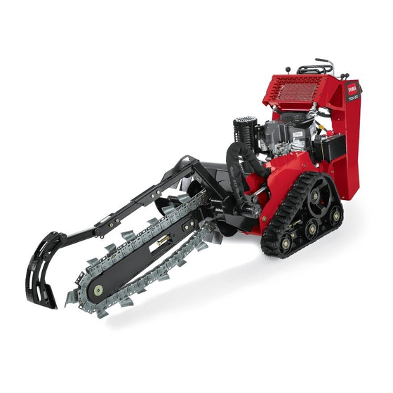
TRX-16, TRX-20, and TRX-26
Trencher
Model No. 22972—Serial No. 315000001 and Up
Model No. 22972G—Serial No. 315000001 and Up
Model No. 22973—Serial No. 315000001 and Up
Model No. 22973G—Serial No. 315000001 and Up
Model No. 22974—Serial No. 315000001 and Up
Form No. 3390-434 Rev A
*3390-434* A
Advertisement
Table of Contents

Related Manuals for Toro TRX-16


Summary of Contents for Toro TRX-16
- Page 1 Form No. 3390-434 Rev A TRX-16, TRX-20, and TRX-26 Trencher Model No. 22972—Serial No. 315000001 and Up Model No. 22972G—Serial No. 315000001 and Up Model No. 22973—Serial No. 315000001 and Up Model No. 22973G—Serial No. 315000001 and Up Model No. 22974—Serial No. 315000001 and Up *3390-434* A Register at www.Toro.com.
- Page 2 CALIFORNIA Proposition 65 Warning You may contact Toro directly at www.Toro.com for product This product contains a chemical or chemicals and accessory information, help finding a dealer, or to register known to the State of California to cause cancer, your product.
-
Page 3: Table Of Contents
Contents Adjusting the Traction Control Alignment ....36 Adjusting the Traction Control Neutral Position .............37 Safety ................4 Adjusting the Tracking of the Traction Control, Safe Operating Practices........... 4 Full Forward Position ..........37 Sound Pressure ............6 Hydraulic System Maintenance ........38 Sound Power ............ -
Page 4: Safety
Safety – Never refuel or drain the machine indoors. • Check that the operator presence controls, safety switches, and shields are attached and functioning properly. Do not Improper use or maintenance by the operator or owner operate unless they are functioning properly. can result in injury. - Page 5 Do not operate on wet grass. Reduced traction could Make any necessary repairs before restarting. cause sliding. • Use only genuine Toro replacement parts to ensure that • Do not park the machine on a hillside or slope without original standards are maintained.
-
Page 6: Sound Pressure
– Charge batteries in an open, well ventilated area, away Sound power level was determined according to the from spark and flames. Unplug the charger before procedures outlined in EN ISO 3744. connecting or disconnecting it from the battery. Wear protective clothing and use insulated tools. -
Page 7: Slope Indicator
Slope Indicator G011841 Figure 3 This page may be copied for personal use. 1. To determine the maximum slope you can safely operate the machine on, refer to the Slope Operation section. Use the slope indicator to determine the degree of slope of hills before operating. Do not operate this machine on a slope greater than that specified in the Slope Operation section. -
Page 8: Safety And Instructional Decals
Safety and Instructional Decals Safety decals and instructions are easily visible to the operator and are located near any area of potential danger. Replace any decal that is damaged or lost. 115-1230 1. Warning—do not operate this machine unless you are trained. 2. - Page 9 115-1231 1. Cutting/dismemberment hazard of bystanders, 6. Explosion hazard; shock hazard—do not use machine near trencher—keep bystanders a safe distance from the machine; buried utility lines; contact the proper agencies before digging. do not operate the trencher chain while transporting the machine.
- Page 10 115-4020 1. Turn right 3. Reverse 2. Forward 4. Turn left 93-7814 1. Entanglement hazard, belt—stay away from moving parts. 100-4650 1. Crushing hazard of hand—keep bystanders a safe distance from the machine. 2. Crushing hazard of foot—keep bystanders a safe distance 93-6686 from the machine.
- Page 11 Battery Symbols Some or all of these symbols are on your battery 1. Explosion hazard 6. Keep bystanders a safe distance from the battery. 2. No fire, open flame, or 7. Wear eye protection; smoking. explosive gases can cause blindness and other injuries 8.
-
Page 12: Setup
Setup Loose Parts Use the chart below to verify that all parts have been shipped. Procedure Description Qty. Boom (sold separately) Install the boom and chain. Chain (sold separately) – No parts required Check the fluid levels. – No parts required Charge the battery. -
Page 13: Checking Fluid Levels
Product Overview 9. Loop the digging chain over the auger drive shaft and onto the drive sprocket, ensuring that the digging teeth point forward on the upper span. 10. Set the upper span of the chain into place on the trencher boom, then wrap the chain around the roller at the end of the boom. - Page 14 Key Switch, Electric Start Models The key switch has three positions: Off, Run, and Start. To start the engine, rotate the key to the Start position. Release the key when engine starts and it will move automatically to the Run position. To stop the engine, rotate the key to the Off position.
- Page 15 Boom Elevation Lever Trencher Control Lever To lower the boom, slowly move the lever forward (Figure To dig with the trencher, rotate the lever rearward and pull it 12). down to the reference bar (Figure 14, number 1). To raise the boom, slowly move the lever rearward (Figure 12).
-
Page 16: Specifications
Contact your Authorized Service Dealer or • Do not store fuel either in the fuel tank or fuel containers Distributor or go to www.Toro.com for a list of all approved over the winter unless a fuel stabilizer is used. attachments and accessories. -
Page 17: Checking The Engine-Oil Level
7. If the oil is below the Add mark, add 10w30 engine oil DANGER to the filler hole, checking the level frequently with the In certain conditions during fueling, static dipstick, until the oil level reaches the Full mark. electricity can be released causing a spark which 8. - Page 18 Figure 18 1. Filler neck cap 2. Hydraulic fluid filter 6. If the level is low, add fluid until it is visible in the glass bubble. 7. Install the cap and filter on the filler neck and torque bolt on top to 13 to 15.5 N-m (110 to 140 inch-lb).
-
Page 19: Starting And Stopping The Engine
Starting and Stopping the Stopping the Engine Engine 1. Move the throttle lever to the Slow position (Figure 19). 2. Lower the boom (Figure 20). Starting the Engine 1. Move the throttle lever midway between Slow and Fast positions (Figure 19). -
Page 20: Digging A Trench
3. Secure the machine to the trailer with chains or straps using the tie-down/lift loops at the front and rear of the machine (Figure 22 Figure 23). Refer to your local ordinances for trailer and tie-down requirements. G007816 Figure 21 1. -
Page 21: Operating Tips
Operating Tips Soil Type Recommended Chain Type Sandy Soil chain (re-configure with • Clean the area of trash, branches and rocks before extra teeth for added digging trenching to prevent equipment damage. speed; refer to your Authorized Service Dealer) • Always begin trenching with the slowest ground speed possible. -
Page 22: Maintenance
Maintenance Note: Determine the left and right sides of the machine from the normal operating position. Recommended Maintenance Schedule(s) Maintenance Service Maintenance Procedure Interval • Change the engine oil. After the first 8 hours • Check and adjust the track tension. After the first 50 hours •... -
Page 23: Premaintenance Procedures
Premaintenance Installing the Cover Plate Procedures 1. Lower the boom, stop the engine, and remove the key. 2. Slide the cover plate into place and secure it with the 3 Before opening any of the covers, stop the engine, remove the bolts you loosened previously (Figure 25). -
Page 24: Lubrication
Lubrication Greasing the Machine Service Interval: Before each use or daily (Grease immediately after every washing.) Grease Type: General-purpose grease. 1. Lower the boom and stop the engine. Remove the key. 2. Clean the grease fittings with a rag. Figure 29 3. -
Page 25: Engine Maintenance
Engine Maintenance 3. Pump grease into the fitting until grease comes out of the grease valve located next to the fitting. 4. Wipe up any excess grease. Servicing the Air Cleaner (Models 22972 and 22973) Service Interval: Every 25 hours—Clean the foam air cleaner element. -
Page 26: Servicing The Air Cleaner (Model 22974)
Cleaning the Foam Air Cleaner Element 1. Wash the foam element in liquid soap and warm water. When the element is clean, rinse it thoroughly. 2. Dry the element by squeezing it in a clean cloth. Important: Replace the foam element if it is torn or worn. -
Page 27: Servicing The Engine Oil
Servicing the Engine Oil 5. Unscrew the oil dipstick and wipe the end clean (Figure 35). Service Interval: After the first 8 hours—Change the engine 6. Slide the oil dipstick fully into the filler tube, but do not oil. thread onto tube (Figure 35). -
Page 28: Servicing The Spark Plug
2. Remove the old filter (Figure 37). Figure 37 Figure 38 1. Oil filter 2. Adapter 1. Spark-plug wire/spark plug 3. Apply a thin coat of new oil to the rubber gasket on 4. Clean around the spark plug to prevent dirt from falling the replacement filter (Figure 37). -
Page 29: Fuel System Maintenance
Installing the Spark Plug Fuel System 1. Install the spark plug and the metal washer. Ensure Maintenance that the air gap is set correctly. 2. Tighten the spark plug to 22 N-m (16 ft-lb). Draining the Fuel Tank 3. Connect the wire to the spark plug (Figure 39). -
Page 30: Replacing The Fuel Filter
Electrical System 9. Wipe up any spilled fuel. Maintenance Replacing the Fuel Filter Service Interval: Every 200 hours Servicing the Battery (Models Never install a dirty filter if it is removed from the fuel line. 22973 and 22974) Note: Note how the fuel filter is installed in order to install Service Interval: Every 25 hours—Check the battery the new filter correctly. - Page 31 5. Remove the hold down plate, j-bolts, and locknuts WARNING securing the battery (Figure 42) and remove the battery. Incorrect battery cable routing could damage the machine and cables causing sparks. Sparks can Installing the Battery cause the battery gasses to explode, resulting in personal injury.
-
Page 32: Replacing The Fuses (Models 22973 And 22974)
1. Remove the battery from the machine; refer to Removing the Battery (page 30). Important: Never fill the battery with distilled water while the battery is installed in the machine. Electrolyte could be spilled on other parts and cause corrosion. 2. -
Page 33: Drive System Maintenance
Drive System Maintenance Servicing the Tracks Cleaning the Tracks Service Interval: Before each use or daily Check the tracks for excessive wear and clean them periodically. If the tracks are worn, replace them. Figure 47 1. Lower the boom and set the parking brake. 2. - Page 34 3. Lift/support the side of the unit to be worked on so 9. Beginning at the drive sprocket, coil the new track that the track is 7.6 to 10 cm (3 to 4 inches) off of the around the sprocket, ensuring that the lugs on the track ground.
-
Page 35: Belt Maintenance
Belt Maintenance 4. Ensure that the road wheel turns smoothly on the bearing. If it is frozen, contact your Authorized Service Dealer to replace the road wheel. Replacing the Pump Drive Belt 5. Place the greased road wheel cap over the bolt head (Figure 51). -
Page 36: Controls System Maintenance
Controls System 5. Adjust the traction control so that it rests flush against the reference bar when it is pulled straight back (Figure Maintenance Figure 55). The factory adjusts the controls before shipping the machine. However, after many hours of use, you may need to adjust the traction control alignment, the Neutral position of the traction control, and the tracking of the traction control in the full forward position. -
Page 37: Adjusting The Traction Control Neutral Position
4. If the machine veers to the right, loosen the left jam WARNING nut and adjust the tracking set screw on the front of the When the machine is running, you could traction control (Figure 57). be caught and injured in moving parts or burned on hot surfaces. -
Page 38: Hydraulic System Maintenance
Fluid (refer to your Authorized Toro Dealer for more information) • Toro Premium All Season Hydraulic Fluid (refer to your Authorized Toro Dealer for more information) • If either of the above Toro fluids are not available, you may use another Universal Tractor Hydraulic... -
Page 39: Checking The Hydraulic Lines
Checking the Hydraulic Lines Service Interval: Every 100 hours—Check the hydraulic lines for leaks, loose fittings, kinked lines, loose mounting supports, wear, weather, and chemical deterioration and repair if necessary. Every 1,500 hours/Every 2 years (whichever comes first)—Replace all moving hydraulic hoses. WARNING Hydraulic fluid escaping under pressure can penetrate skin and cause injury. -
Page 40: Trencher Maintenance
Trencher Maintenance B. Loosen the jam nut on the adjusting bolt in the boom. C. Loosen the adjusting bolt until you can remove Replacing the Digging Teeth the chain from the boom D. Remove the chain from the drive sprocket. Service Interval: Before each use or daily—Check the condition of the digging teeth and E. - Page 41 17. Thread the jam nut down the adjusting bolt and tighten it securely against the boom. 18. Torque the 2 bolts and nuts securing the boom to 183 to 223 N-m (135 to 165 ft-lb). 19. Install the spoils auger using the bolt and nut you removed previously.
-
Page 42: Cleaning
Cleaning Storage 1. Lower the boom and set the parking brake. Removing Debris from the 2. Stop the engine, remove the key, and wait for all moving Machine parts to stop before leaving the operating position. 3. Remove dirt and grime from the external parts of the Important: Operating the engine with blocked screens, entire machine, especially the engine. - Page 43 12. Charge the battery (model 22973 and 22974); refer to Servicing the Battery (Models 22973 and 22974) (page 30). 13. Check and adjust the track tension; refer to Checking and Adjusting the Track Tension (page 33). 14. Check and adjust the digging chain tension; refer to Checking and Adjusting the Digging Chain and Boom (page 40).
-
Page 44: Troubleshooting
Troubleshooting Problem Possible Cause Corrective Action The starter does not crank (models 22973 1. The battery is discharged. 1. Charge the battery or replace it. and 22974). 2. The electrical connections are 2. Check the electrical connections for corroded or loose. good contact. - Page 45 Problem Possible Cause Corrective Action The trencher does not dig fast enough. 1. The digging teeth are worn. 1. Replace the digging teeth. 2. The chain you are using is not 2. Evaluate the ground type and change appropriate for the type of ground. chains if necessary.
-
Page 46: Schematics
Schematics Electrical Schematic—Model 22972 (Rev. A) - Page 47 Electrical Schematic—Model 22973 (Rev. A)
- Page 48 Electrical Schematic—Model 22974 (Rev. A)
- Page 49 Hydraulic Schematic (Rev. C)
- Page 50 Notes:...
- Page 51 The Way Toro Uses Information Toro may use your personal information to process warranty claims, to contact you in the event of a product recall and for any other purpose which we tell you about. Toro may share your information with Toro's affiliates, dealers or other business partners in connection with any of these activities. We will not sell your personal information to any other company.
- Page 52 Toro importer. If all other remedies fail, you may contact us at Toro Warranty Company. Australian Consumer Law: Australian customers will find details relating to the Australian Consumer Law either inside the box or at your local Toro Dealer.