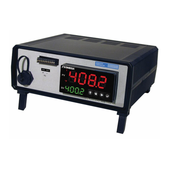
Omega Platinum Series User Manual
Universal benchtop digital controller
Hide thumbs
Also See for Platinum Series:
- Quick start manual ,
- User manual (61 pages) ,
- User manual (79 pages)
Table of Contents
Advertisement
U.S.A.:
Omega Engineering, Inc.
Toll-Free: 1-800-826-6342 (USA & Canada only)
Customer Service: 1-800-622-2378 (USA & Canada only)
Engineering Service: 1-800-872-9436 (USA & Canada only)
Tel: (203) 359-1660 Fax: (203) 359-7700
e-mail: info@omega.com
For Other Locations Visit omega.com/worldwide
The information contained in this document is believed to be correct, but OMEGA accepts no liability for any errors it
contains, and reserves the right to alter specifications without notice.
CS8DPT/CS8EPT
Universal Benchtop
Omega.com info@omega.com
Servicing North America:
Digital Controller
Advertisement
Table of Contents

Related Manuals for Omega Platinum Series


Summary of Contents for Omega Platinum Series
- Page 1 Tel: (203) 359-1660 Fax: (203) 359-7700 e-mail: info@omega.com For Other Locations Visit omega.com/worldwide The information contained in this document is believed to be correct, but OMEGA accepts no liability for any errors it contains, and reserves the right to alter specifications without notice.
-
Page 2: Table Of Contents
3.4 Rear Panel ............................. 8 3.5 Isolated Analog Output ......................... 8 4 CONFIGURATION AND PROGRAMMING ................9 4.1 PLATINUM Series Navigation ......................9 4.2 Selecting an Input (INIt>INPt) ..................... 10 4.3 Set the Setpoint 1 Value (PRoG > SP1) ..................10 4.4 Set up the Control Output ...................... -
Page 3: Introduction
CAUTION, refer to accompanying documents 1.3 Statement on CE Marking OMEGA’s policy is to comply with all worldwide safety and EMI/EMC regulations that apply to CE Certification standards, including EMC Directive 2014/30/EU Low Voltage Directive (Safety) Directive 2014/35/EU, and EEE RoHS II Directive 2011/65/EU. OMEGA is constantly pursuing certification of its products to the European New Approach Directives. -
Page 4: Communication Options
Unpacking 1.5 Communication Options The Platinum Series Benchtop Digital Controller comes with a USB port standard. Optional Serial and Ethernet connectivity is also available. All communication channels can be used with the Omega Platinum Configurator software and support both the Omega ASCII protocol and the Modbus Protocol. -
Page 5: Power Cords
Hardware Setup 2.2 Power Cords Electrical power is delivered to the Benchtop Digital Controller by an AC power cord which plugs into the IEC 60320 C-13 power socket located on the rear panel of the unit. Refer to Figure 7 for detailed connections. The input power is fused on the Line terminal. -
Page 6: 10-Pin Connector Wiring Diagrams
Hardware Setup 3.2 10-PIN Connector Wiring Diagrams The 10-pin universal input connector pin assignments are summarized in Table 4. Table 4. 10-Pin Input Connector Wiring Code Description ARTN Analog return signal (analog ground) for sensors and remote Setpoint AIN+ Analog positive input AIN- Analog negative input APWR... -
Page 7: Universal Thermocouple Connector
Figure 4 shows the wiring diagram for the process current input using either internal or external excitation. The benchtop unit provides 5V excitation by default and can also output 10V, 12V or 24V excitation voltages. Refer to the Platinum Series User’s Manual (M5451) for more information on selecting the excitation voltage. -
Page 8: Rear Panel
Hardware Setup 3.4 Rear Panel The power, fuses and outputs are located on the rear panel of the Benchtop Digital Controller. The optional Ethernet port is also located at the rear of the unit. Figure 7. Rear Panel. (Not to scale) Table 6. -
Page 9: Configuration And Programming
This section outlines the initial programming and configuration of the Benchtop Digital Controller. It gives a brief outline on how to setup the inputs and outputs, and how to configure the setpoint and control modes. Refer to the Platinum Series User’s Manual (M5451) for more detailed information on all the controller’s functions. -
Page 10: Selecting An Input (Init>Inpt)
Configuration and Programming 4.2 Selecting an Input (INIt>INPt) The Benchtop Digital Controller features a Universal Input. The input type is selected in the Initialization Menu. Select the input type by navigating to the Input sub-menu (INIt>INPt). Available Input types are shown in Table 8. Table 8. -
Page 11: Set Up The Control Output
Configuration and Programming 4.4 Set up the Control Output The outputs and control parameters of the unit are set up in the Programming (PRoG) Menu. The unit is configured with a 3A Mechanical Relay and a 5A Solid State Relay. An optional Isolated Analog Output is also available. -
Page 12: Pid Control
Configuration and Programming 4.6 PID Control PID control mode is required for Ramp and Soak applications or for finer process control. For Mechanical Relay and SSR outputs, the output will be on a percentage of time based on the PID control values. The frequency of switching is determined by the (CyCL) parameter for each output. -
Page 13: Retransmission Using The Analog Output
Configuration and Programming 4.7 Retransmission Using the Analog Output The optional Analog Output can be configured to transmit a Voltage or current signal proportional to the Input. Select the output type in the PRoG > IAN.1 > RNGE menu. For a more detailed discussion of setting up and configuring the Analog Output refer to the Platinum Series User’s Manual (M5451). -
Page 14: Specifications
5 SPECIFICATIONS Table 9 is a summary of the specifications unique to the Benchtop Digital Controller. It take precedence where applicable. For detailed specifications refer to the Platinum Series User’s Manual (M5451). Table 9. Benchtop Digital Controller Specifications Summary. Model CS8DPT/CS8EPT... -
Page 15: Maintenance
Refer to the Platinum Series User’s Manual (M5451) for additional information on user calibration options. Optional NIST traceable calibration is available. Please contact Customer Service to enquire. - Page 16 Department will issue an Authorized Return (AR) number immediately upon phone or written request. Upon examination by OMEGA, if the unit is found to be defective, it will be repaired or replaced at no charge. OMEGA’s WARRANTY does not apply to defects resulting from any action of the purchaser, including but not limited to mishandling, improper interfacing, operation outside of design limits, improper repair, or unauthorized modification.
Need help?
Do you have a question about the Platinum Series and is the answer not in the manual?
Questions and answers