
Related Manuals for Saeco D.A. COMBISNACK


Summary of Contents for Saeco D.A. COMBISNACK
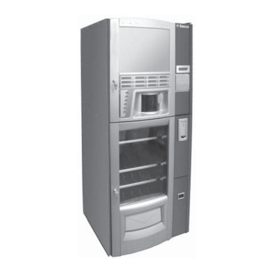
- Page 1 Vending Machine COMBISNACK D.A. WARNING: This instruction manual is intended exclusively for specialized personnel.
-
Page 2: Main Parts
English MAIN PARTS Display 23 Coffee bean hopper 45 Mobile drip tray Instruction plate 24 Coffee grinder 46 Anti-overflow valve drain hose Dispensing outlet door (Beverage/ 25 CPU card 47 Air break device drain hose Cup dispensing) 26 Cup dispenser 48 Drip Tray Coin slot 27 Dispensing outlet... - Page 3 English 17 19 46 47 Fig. 1...
-
Page 4: Table Of Contents
English CONTENTS MAIN PARTS ............2 CONTENTS ............4 PROGRAMMING AND MAINTENANCE MENU ............32 INTRODUCTION TO THE MANUAL ..5 8.1 Description of programming and maintenance 1.1 Foreword ........... 5 phase keys ..........32 1.2 Symbols used ..........5 8.2 Programming menu ........ -
Page 5: Introduction To The Manual
Manufacturer: SAECO International Group Via Panigali, 39 - 40041 Gaggio Montano (BO) – ITALIA. Maintenance technician It is used to indicate operations to be performed only by This manual must be preserved with care and must be skilled maintenance technicians. -
Page 6: Description And Intended Use
English The Maintenance Technician must read carefully and any alteration to components and/or safety devices respect the warnings on safety contained in this manual not previously authorized by the Manufacturer and so that every intervention concerning installation, carried out by staff not authorized for such operations. activation, operation and maintenance will be carried out under safe conditions. -
Page 7: Technical Specifications
English Technical specifications Capacity of containers (HOT DRINKS) Coffee beans: ............ 2,7 kg Weight: ............240 kg Decaffeinated coffee: ........0,6 kg Overall dimensions: ........see figure 3 Chocolate: ............2,9 kg Milk: ..............1,6 kg Lemon tea: ............2,2 kg Sugar: .............. -
Page 8: Safety
Tension Directive 73/23/EEC and CE Marking Directive 93/68/EEC, the SAECO International Group has Precautions to prevent errors: drawn up a technical file on D.A. COMBISNACK make the operators conscious of the problems of safety; vending machine at its plants, acknowledging the following... -
Page 9: Safety Devices
English Warning The Supply Operator is not authorized to carry out operations that are indicated as competency of the Maintenance technician in this publication. Maintenance technician The only person authorized to intervene and start the programming procedures, adjust, set up and upkeep the machine. -
Page 10: Residual Risks
English Residual risks HANDLING AND STORAGE The dispensing outlet is protected by the door interlocked by the safety switch. If it is opened during the brewing cycle, the mechanical Unloading and handling movement is blocked, but if brewing has already started, it continues to the end of the cycle. -
Page 11: Storage
English Warning The machine must always be kept in the upright position. Avoid (Fig. 11): dragging the vending machine; tipping over or laying down the vending machine during transport and handlingt; shaking the vending machine; raising the vending machine with ropes or cranes; leaving the vending machine exposed to bad weather or humid areas or near sources of heat. -
Page 12: Unpacking And Positioning
English Where the vending machine needs to be positioned near Instruction booklet. a wall, it is necessary to leave a space of at least 15cm between the back and the wall to leave the air outlet grill Power cord. free (Fig. 13). Disabling keys of doors safety microswitches ( Maintenance Technician). - Page 13 English Use a forklift truck (Fig.16) to lift the pallet. In this way the four fixing bolts A can be removed. Fig. 17 Raise the vending machine to be able to bolt on the four feet B (Fig. 18). During this operation an operator will hold the lower door.
- Page 14 English Lean the vending machine slightly and remove the first spacer (Fig. 21). Important If the area can only be reached through a transpallet, follow this procedure: Place two spacers (more than 10 cm in height) under the vending machine feet. Rest the vending machine on the spacers very carefully (Fig.19).
- Page 15 English Rest the vending machine gently on the floor (Fig. 23). Take out the keys from the change outlet ( Fig. 25). Fig. 25 Fit the key into the HOT DRINKS lock, turn clockwise and open the door (Fig. 26). Fig.
-
Page 16: Setting The Tray
English Fit the key into the SNACKS lock, turn clockwise and Setting the tray open the door (Fig. 28) Figure 31 shows one of the possible tray configurations foreseen by the Manufacturer. Bottles tray Bottles tray Snacks tray Tray Fig. 28 Snack/cans tray Remove the adhesive tape that fixes the spirals and the dispensing channels (Fig. -
Page 17: Connection Of Trays And Spiral Motors
English The snacks trays can be composed of single and/or double spirals powered by a single motor (Fig. 33). Important In case one motor drives two spirals, these must have the same pitch (one right and one left). To ease product dispensing, a guide channel shall be inserted under each spiral (Fig. -
Page 18: Plates And Stickers Fitting
English Plates and stickers fitting. Important When a tray is connected to a different connector, the Plates and stickers are contained in the CUSTOMER KIT. products will be identified by a new selection number. The vending machine self-configures whenever the vending Plates with codes and prices of snacks machine is switched on. - Page 19 English Remove the transparent protection cover (Fig. 41). Instruction plate Remove both lower fastening screws of panel (Fig. 38). Fig. 41 Insert the plate into the internal part of the transparent protection cover (Fig. 42). Fig. 38 Remove both front fastening screws of panel (Fig. 39). Fig.
- Page 20 English Apply the adhesive labels of the prices on the appropriate Remove the strip second fastening screw (Fig. 47). space, next to the corresponding description (Fig. 44). Fig. 47 Fig. 44 Remove the strip (Fig. 48). After applying the labels, put the adhesive protection (Fig. 45).
-
Page 21: Coffee Grounds Bag Fitting
SERVICE CENTERS to carry out programming and/or data collection operations. Assembly of the payment systems On the D.A. COMBISNACK vending machine different payment systems can be preset, namely: parallel banknote reader 24V DC; parallel coiner 24V DC; executive systems (also PRICE HOLDING);... -
Page 22: Water System Connection
English 5.10 Electric connection Warning The Manufacturer declines any responsibility for damages Warning to the vending machine and other objects and for personal injuries caused by an incorrect installation of the payment The Maintenance Technician, who is responsible for the system. -
Page 23: Controls Description
English Display CONTROLS DESCRIPTION The display (1 - Fig. 1) shows the messages during the standard functioning, programming and maintenance phases. Main switch It is located in the rear side of vending machine, bottom right (Fig.1 – 58). “I” position: the machine is on. -
Page 24: Description Of Keys In Ordinary Dispensing Mode
English Description of keys in CPU card keys ordinary dispensing mode The CPU electronic card has three keys that allow the HOT DRINKS SECTION Maintenance Technician to program or upkeep the system (Fig. 60). Decaffeinated Key (7 – Fig. 59) This preselection key will be active only if the “DECA PRESELECTION”... -
Page 25: Supply And Operation
English Move the container to the supporting bracket (Fig. 63). SUPPLY AND OPERATION HOT DRINKS container supply Important It is necessary to use soluble products considered suitable for automatic distribution . During the programming phase, when the display shows: “BEVERAGE PREPARATION” (see 8.2.3), pour lyophilized products into the relevant containers. -
Page 26: Sugar Supply
English Move the container to the supporting bracket (Fig. 67). 7.1.2 Sugar supply Remove the sugar elbow (Fig. 65). Fig. 67 Pour the sugar inside the container (Fig. 68) without exceeding 2/3 of the maximum capacity. Fig. 65 Remove the container (Fig. 66). Fig. -
Page 27: Coffee Bean Supply
English 7.1.3 Coffee bean supply Grinding adjustment Remove the lid of the container (Fig. 69). Turn the knob until reaching the desired index number (Fig. 71). The values of reference for correct grinding are: Italy:………………………..…………….. 4 - 7 Spain:…………………………………….. 5 - 8 France - Switzerland: ……………………... -
Page 28: Stirrer Supply
English Insert the packet of stirrers (Fig. 74). Stirrer supply Important Use stirrers suited to automatic distribution, without imperfections and conforming to the dimensions indicated in sect. 2.4 Technical Data. Press the locking clip and rotate the stirrer dispenser towards the outside (Fig. 72). Fig. -
Page 29: Cups Supply
English Insert the counterbalance bar (Fig. 76). Cups supply Important This is a very delicate operation. Lack of respect for the instructions provided at this point could cause serious damage to the cup distributor. The rotation of the cup column must be carried out with the door open to be able to see the operation as it happens. -
Page 30: Snacks Supply
English Widen the lateral sides (Fig. 80). SNACKS supply Important It is essential to use cold snack/drinks products that do not require specific temperatures for their preservation. Open the door and slide the trays towards the outside until they block (see at sect. 5.3 the composition of the trays and the spirals). -
Page 31: First Switching On
Set the main switch (5 - Fig. 1) to the “I” (ON) position. The washing operation must be repeated until no water flows out of the dispensing nozzles. At this point the message “SAECO combi SAECO” will be displayed and the self-configuration that controls all of the settings previously defined begins, i.e.: presence and condition of the motors;... -
Page 32: Programming And Maintenance Menu
English Programming menu PROGRAMMING AND MAINTENANCE MENU The structure of the programming menu is shown in 8.2.2. At 8.2.3 all of the entries present in the programming menu are described. Important This section illustrates how to set up or modify the machine 8.2.1 Entering the programming and maintenance parameters. -
Page 33: Structure Of The Programming Menu
Entries selectable only with complete menus FLOW METER FLOW METER COFFEE COFFEE FLOW METER BEVERAGES TEXT STAND-BY TEXT STAND-BY SAECO COMBI SNACK COMBI SNACK TEXT DISPENSING TEXT DISPENSING WAIT FOR PRODUCT WAIT FOR PRODUCT TEXT OUT OF SERVICE TEXT OUT OF SERVICE... - Page 34 English INSTANT CYCLE INSTANT CYCLE >Y< MULTIPLE BEVERAGE MULTIPLE BEVERAGE MULTIPLE BEVERAGE > < ON/off:ABCDEFGHI BEVERAGES BEVANDE BEVARAGES ACTIVATED YES: ABCDefGHI FREE VEND BUTTON FREE VEND BUTTON >Y< CUP BUTTON CUP BUTTON ENABLE DISABLE Entries selectable only with complete menus ENABLE RESET ENABLE RESET >Y<...
- Page 35 English MULTIVEND MULTIVEND >Y< OVERPAY TIME OVERPAY TIME Entries selectable only SCALING FACTOR SCALING FACTOR with complete menus NATION CODE NATION CODE 0039 0042 DECIMAL POINT POSIT. DECIMAL POINT POSIT. 0000 00.00 PREPAR. BEVERAGE PREPAR. BEVERAGE BEVERAGE BEVERAGE SEQUENCE 003C BEVERAGE BEVERAGE PREPAR.
- Page 36 English SNACK PRICES SNACK PRICES SET GLOBAL GLOBAL NORMAL 001: 200 GLOBAL nnn: 500 SET SINGLE SINGLE 001:200 SINGLE nnn:1200 CUP PRICES CUP PRICES 001: 200 PRICE DISCOUNT PRICE DISCOUNT > < TIME MANAGEMENT FREE FREE NEVER NEVER SYSTEM MANAGEMENT FREE ALWAYS To set the 3 PRICE level at 550 ITL:...
-
Page 37: Description Of Messages In The Programming Menu
English 8.2.3 Description of messages in Cold temperature It allows to assign a service temperature of the the programming menu refrigerating compartment between +8°C and +15°C. Compressor SYSTEM MANAGEMENT It allows to desactivate or activate the compressor. The entries of the SYSTEM MANAGEMENT ARE: Tank VM Code It allows sensor level (optional) reading inside the... - Page 38 English Example: to set the value 12353 it is necessary to press: Beverages validation It allows to enable or disable the beverage keys. 12 times the E beverage key; 3 times the C beverage key; 5 times A key; Example: VALIDATION DEVERAGES YES: ABCDefGHI 3 times UP key;...
- Page 39 It allows the user to set the nation code (international combination of digits “C300” or “C030” or “0C30”, code) as required by the SAECO-NET program. product 3 and coffee beans will always be dispensed. On the basis of the sequence the settings of the...
- Page 40 English BEVERAGE Water soluble: H2O SOLUBLE. 3: Important It defines the quantity of water to mix with soluble in In case the sequence includes more soluble products, the powder. sequence “SOLUBLE - WATER - % SOLUBLE” will appear Example: “3” indicates that water will be mixed with again.
- Page 41 English PRICE MANAGEMENT SINGLE Setting single: The items of the PRICE MANAGEMENT are: 003: 500 It allows to select the price level to combine with each snack. PRICE TABLE Price table: Move to the desired selection with the UP and DOWN PRICE 003: keys, press ENTER (the cursor will move from S11 to 99 levels of prices can be set.
-
Page 42: Maintenance Menu
English Maintenance menu The structure of the maintenance menu is shown in 8.3.2. At 8.3.3 all of the entries present in the maintenance menu are described. 8.3.1 Access to the maintenance menu Open the upper door, disable the safety device (see 3.4) and press key 2 (Fig. -
Page 43: Structure Of The Maintenance Menu
English 8.3.2 Structure of the maintenance menu This message appears only if there is an MAINTENANCE ERROR MESSAGE error, otherwise “WASHING” appears. ERROR LOG ERROR LOG Mxx Eyy dd/mmm hh:mm RINSING TIME DRAIN BOILER DRAIN BOILER >Y< CONTROL MOTORS MOTORS B.DOWN MOTOR MOTOR MOTOR... -
Page 44: Maintenance Menu
English Example of verification of a parameter. 8.3.3 Descripition of message in the maintenance menu MAINTENANCE MAINTENANCE CONTROL MOTORS In this function it is possible to show and reset the errors that may be present. It is also possible to upkeep the vending machine. - Page 45 English By pressing ENTER again after viewing the last screen, the user will remove the errors. Recommended solutions Error Removal (Attempt to remove) In maintenance mode it is possible to: The VM tries, in sequential order, to remove move the gearmotor of the coffee unit by pressing automatically the errors.
- Page 46 The VM will display again all the information (including erased information) beverage button 5 Getting the total number of stored Press the snack buttons “1” and SAECO COMBI SAECO errors (with the VM in the standard “3” simultaneously operation mode) Note...
-
Page 47: Operation And Use
English REMEDIES FAILURE OPERATION AND USE Check the motor and “51” Incorrect microswitch eliminate the failure. Reset switching times of motor. and check motors. If the problem persists, contact Beverage selection your Authorized Customer (HOT DRINKS) Service Center. The machine can dispense 9 beverages. Eliminate the failure. -
Page 48: Selection Of Products (Snacks)
Take the beverage from the dispensing outlet. Important After closing the door the display will show the message “THANK YOU” and after a few seconds “SAECO combi During dispensing: SAECO” (vending machine is awaiting selection). payment systems are disabled;... -
Page 49: Cleaning And Maintenance
English 10.2 Cleaning and routine 10 CLEANING AND maintenance MAINTENANCE Warning Every component part has to be rinsed exclusively with Warning warm water without using any detergent or solvent that could modify its shape or performance. Before performing any maintenance and/or cleaning Do not wash removable components in the dishwasher. -
Page 50: Drip Tray Cleaning
English Each supply 10.2.3 Coffee grounds bag • If necessary, clean the coffee bean hopper, the soluble replacement product and sugar containers (see 10.2.9). Tighten the clip, extract the full bag and replace it with a Monthly new one (Fig. 91). •... -
Page 51: Stirrer Channel Cleaning
English Remove the hose from the tank (Fig. 93). 10.2.6 Coffee brewing unit cleaning Disconnect the tube of the dispensing arm (Fig. 96). Fig. 93 Remove the cap (Fig. 94) and empty the fluid tank. Fig. 96 Remove the coffee brewing unit keeping the lever in position 3 (Fig. -
Page 52: Soluble Product Dispenser And Mixer Cleaning
English Wash the unit with lukewarm water. Clean specially the 10.2.7 Soluble product upper filter (Fig. 98). dispenser and mixer cleaning Upper filter Disconnect the dispensing hose from the nozzle and the dispensing arm (Fig. 100). Fig. 98 Important While inserting the unit make sure that reference arrows are aligned. -
Page 53: Dispensing Outlet Cleaning
English Screw the blocking ring clockwise (Fig. 102) and remove 10.2.8 Dispensing outlet the mixer case. cleaning By shifting the locking levers remove the dispensing outlet. (Fig. 104). Fig. 104 Remove the lower plate (Fig. 105). Fig. 102 With a flat screwdriver, levering carefully, remove the fan (Fig. - Page 54 English Assemble the dispensing outlet into the vending machine Remove the ring protective flange (Fig. 109). and check that the upper pin is not between the door wall and the microswitch tongue (Fig. 107). Fig. 109 Rotate the upper ring anticlockwise and remove it from the outlet (Fig.
-
Page 55: Tanks And Containers Cleaning
English Press carefully on the sides and slide out the dispensing 10.2.9 Tanks and containers outlet door (Fig. 111). cleaning To clean the coffee bean hopper you need to: pull outwards the moving panel (Fig. 113); Dispense some coffee cups in order to empty the coffee grinder from coffee beans. - Page 56 English remove the container (Fig. 115). remove the container (Fig. 117). Fig. 115 wash the inside of the container and dry it carefully before reassembling it. Fig. 117 wash the container and dry it carefully before reassembling it. To clean the sugar container you need to: remove the elbow of sugar (Fig.
-
Page 57: Dispensing Arm Cleaning
English Lift the locking lever and remove the mobile drip tray. (Fig. 10.2.10 Dispensing arm cleaning 121). Disconnect the hoses from the dispensing arm (Fig. 119). Fig. 121 Wash all components with lukewarm water and reassemble it proceeding in reverse order. Fig. -
Page 58: Refrigerating Unit Cleaning
English Wash the components in lukewarm water and carry out Use a hoover to clean the refrigerating unit and the inside the inverse procedure to assemble it. of the compartment (Fig. 124). 10.2.12 Refrigerating unit cleaning Remove the lower covering (Fig. 123). Fig. -
Page 59: Unscheduled Maintenance
English 10.3 Unscheduled maintenance Warning All of the aforementioned warnings (10.2) are valid also in cases of unscheduled maintenance. 45° Unscheduled maintenance concerns the replacement and the adjustment of components where it is necessary to have specific knowledge and it foresees: the adjustment of the spirals (procedure described at 10.3.1);... -
Page 60: Spiral Replacement
English fit the most suitable spiral to the product to be 10.3.2 Spiral replacement dispensed. Fit it into the drive flange of motor carrying out the inverse procedure; In the standard version some spirals with different pitches are supplied, suitable for dispensing products of different adjust the spiral as indicated at 10.3.1. -
Page 61: Motor Replacement
English fit the snack conveyor (Fig. 131); 10.3.3 Motor replacement The procedure is the following: remove the tray from the vending machine and rest it on the workbench; remove the motor and the spiral from the tray (Fig. 126); remove the spiral (Fig. 127); remove the electrical connectors (Fig. -
Page 62: Modifications To The Layout Of The Trays
English choose the desired seat in the vertical rod to reposition 10.3.4 Modifications to the the guide channel. Retighten the previously removed layout of the trays screw; It is possible to modify the position of the trays inside the disassemble and reposition the left guide channel in vending machine moving the guides supporting them. -
Page 63: Software Updating
English switch on the vending machine. The vending machine 10.4 Software updating checks if a suitable external memory is present. It this is the case, the following message is displayed: The v.m. control program is in the flash memory inside the microcontroller. -
Page 64: Display Messages
This section will show the messages displayed: during normal operation; in case of failure (error messages). Error cedes Message Cause Remedy SAECO combi SAECO The vending machine is waiting. WAIT FOR PRODUCT Beverage dispensing in progress. CLOSE DOOR Dispensing outlet door open Close the door... - Page 65 Network frequency detection switch it on again. errors. No brew group Fit the brew group properly DRINKS with coffee Saeco card without timekeeper. Remove the cause of the message Vending ERROR 27. machine Compressor working for more Switch off the vending machine.
-
Page 66: Storage - Disposal
English turn off the vending machine through switch 15 (Fig. 12 STORAGE - DISPOSAL empty the coffee grounds bag (see 10.2.3); empty the discharge fluid tank and wash it (see 10.2.4); clean the vending machine as indicated in section 10; reassemble the components and close the doors;... - Page 67 English...
Need help?
Do you have a question about the D.A. COMBISNACK and is the answer not in the manual?
Questions and answers