Haulotte COMPACT 8 Operating And Maintenance Instructions Manual
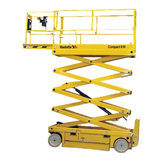
Self-propelled scissor platform
Hide thumbs
Also See for COMPACT 8:
- Operator's manual (140 pages) ,
- Maintenance book (118 pages) ,
- Operator's manual (126 pages)

Related Manuals for Haulotte COMPACT 8


Summary of Contents for Haulotte COMPACT 8
- Page 1 OPERATING AND MAINTENANCE INSTRUCTIONS SELF-PROPELLED SCISSOR PLATFORM COMPACT 8, 8W, 10N, 10 and 12 242 032 6060 - E 04.07 GB...
- Page 3 Main tool free 1-877-HAULOTTE Fax / Fax + 44 (0) 1952 292758 Service tool free 1-877-HAULOT-S Haulotte Singapore Pte Ltd Haulotte Netherlands BV Tél / Phone + 65 6536 3989 Tél / Phone + 31 162 670 707 Fax / Fax...
- Page 5 REVIEW JOURNAL Issue Date Subject 11.06 25.10.06 DM5791 04.07 27.04.07 DM5790 - DM5960 - DM6113...
- Page 7 Operation and maintenance GENERAL You have just taken delivery of your mobile elevating work platform It will give you complete satisfaction if you follow the operating and maintenance instructions exactly. The purpose of this instruction manual is to help you in this. We stress the importance: •...
- Page 8 Operation and maintenance...
-
Page 9: Table Of Contents
Operation and maintenance CONTENTS GENERAL RECOMMENDATIONS - SAFETY ............1 1.1 - GENERAL WARNING ....................1 1.1.1 - Manual ............................. 1 1.1.2 - Labels ............................1 1.1.3 - Safety............................1 1.2 - GENERAL SAFETY INSTRUCTIONS................. 2 1.2.1 - Operators ..........................2 1.2.2 - Environment.......................... - Page 10 2.4.5 - Work area, Compact 12 ......................13 2.5 - TECHNICAL CHARACTERISTICS ................14 2.5.1 - Compact 8, 8W technical characteristics ................14 2.5.2 - Compact 10N, 10 technical characteristics ................15 2.5.3 - Compact 12 technical characteristics..................16 2.6 - OVERALL DIMENSIONS ...................17...
- Page 11 USING THE MACHINE ....................31 4.1 - GENERAL INSTRUCTIONS..................31 4.1.1 - The machine's environment ....................31 4.1.1.1 - Outdoors (Compact 8, 8W, 10, 12)....................... 31 4.1.1.2 - Indoors..............................31 4.1.2 - Manual extension........................32 4.2 - OFFLOADING - LOADING ..................32 4.2.1 - Offloading by lifting ........................
- Page 12 Operation and maintenance 4.4 - DRIVING ........................36 4.4.1 - General recommendations ..................... 36 4.4.2 - Operations from the ground ....................37 4.4.2.1 - Recommendations ..........................37 4.4.2.2 - Procedure ............................. 37 4.4.3 - Operation from the platform ....................37 4.4.3.1 - Recommendations: ..........................37 4.4.3.2 - Procedure .............................
- Page 13 Operation and maintenance 5.4.2 - Procedure ..........................46 5.4.2.1 - Hydraulic oil reservoir ........................... 47 5.4.2.2 - Hydraulic oil filter ..........................47 5.4.2.3 - Greasing of pivot pin on steered wheels:....................47 5.4.3 - Greasing of the slideways:....................48 5.4.4 - List of consumables ....................... 48 5.5 - MANUFACTURER’S RECOMMENDATIONS ............
- Page 14 8.3.6 - A1: Angle sensor ........................60 8.3.7 - G1: Pressure sensor ......................60 HYDRAULIC DIAGRAMS ..................63 9.1 - HYDRAULIC COMPONENTS (COMPACT 8, 8W, 10N, 10) ........63 9.2 - HYDRAULIC DIAGRAM 118P251510B ..............64 1.9 - HYDRAULIC COMPONENTS FOR COMPACT 12 ...........65 1.10 - HYDRAULIC DIAGRAM 121P251530B ..............66...
-
Page 15: General Recommendations - Safety
GENERAL WARNING 1.1.1 - Manual The purpose of this manual is to help the operator to get to know HAULOTTE self- propelled lifts so as to use them efficiently and SAFELY. It cannot, however, replace the basic training necessary for any user of site plant. -
Page 16: General Safety Instructions
Caution! Only trained operators can There must be at least two operators so that one of them can: use Haulotte self-propelled • Intervene quickly if necessary. lifts. • Take the controls in the event of an accident or breakdown. - Page 17 Operating and maintenance instructions In order to avoid any risk of a serious fall, it is essential for operators to comply with the following instructions: • Hold on to the guard rails firmly when the lift is being raised or driven. •...
-
Page 18: Residual Risks
- discharge of an equilibrium valve, - discharge of a pressure limiter, etc. If abnormal noise is detected, the user must stop using the equipment immediately and contact the PINGUELY HAULOTTE After-Sales department to detect the source of the problem. 1.4 - VERIFICATIONS Comply with the national regulations in force in the country of use. -
Page 19: Examination Of Suitability Of A Machine
(concerns mechanics, hydraulics and electricity). They must be carried out by PINGUELY-HAULOTTE personnel or personnel working on behalf of PINGUELY-HAULOTTE who must use original parts only. Any modification outside PINGUELY-HAULOTTE's control is not authorised. The manufacturer is not liable if original parts are not used or if the work specified above is not carried out by PINGUELY-HAULOTTE approved personnel. -
Page 20: Beaufort Scale
Operating and maintenance instructions 1.7 - BEAUFORT SCALE The Beaufort Scale of wind force is accepted internationally and is used when communicating weather conditions. It consists of number 0 - 17, each representing a certain strength or velocity of wind at 10m (33 ft) above ground level in the open. -
Page 21: Presentation
Operating and maintenance instructions - COMPACT 8, 8W, 10N, 10, 12 PRESENTATION Compact 8, 8W, 10N, 10 and 12 self-propelled lifts are designed for any high work within the limit of their characteristics (see Chapter 2.5, page 14) and complying with all the safety instructions particular to the machine and to the locations where it is used. -
Page 22: Main Components
Operating and maintenance instructions - COMPACT 8, 8W, 10N, 10, 12 2.3 - MAIN COMPONENTS 01 - Drive/steered front wheel 10- Anchoring point 02 - Platform 11- Rear wheel 03 - Extensions 12,15 - Location for the fork-lift truck forks... -
Page 23: Work Area
Operating and maintenance instructions - COMPACT 8, 8W, 10N, 10, 12 2.4 - WORK AREA 2.4.1 - Work area, Compact 8 FEET 15 9 8 1/2" 1/4" 3.14 m / 3 ft 3 72 cm / 2 ft 2 24 7 21 6 92 cm / 3 ft 18 5 15 4 12... -
Page 24: Work Area, Compact 8W
Operating and maintenance instructions - COMPACT 8, 8W, 10N, 10, 12 2.4.2 - Work area, Compact 8W 15 FEET 9 27 8 1.11 m / 3 ft 7 3.14 m / 10 ft 3 1/2" 1/2" 24 7 21 6 92 cm / 3 ft 18 5 15 4 12 3 9 2 6 1... -
Page 25: Work Area, Compact 10N
Operating and maintenance instructions - COMPACT 8, 8W, 10N, 10, 12 2.4.3 - Work area, Compact 10N FEET 15 1/2 " 1/4 " 72 cm / 2ft 4 3.14 m / 10 ft 3 9 27 8 92 cm / 3 ft 24 7 21 6 18 5 15 4 12 3 9 2 6 1... -
Page 26: Work Area, Compact 10
Operating and maintenance instructions - COMPACT 8, 8W, 10N, 10, 12 2.4.4 - Work area, Compact 10 FEET 15 1/2" 1.11 m / 3 ft 7 9 27 8 92 cm / 3 ft 24 7 21 6 18 5 15 4 12 3 9 2 6 1 3... -
Page 27: Work Area, Compact 12
Operating and maintenance instructions - COMPACT 8, 8W, 10N, 10, 12 2.4.5 - Work area, Compact 12 FEET 15 1/ 2 " 1/ 2 " 3.14 m / 10 ft 3 1.11 m / 3 ft 7 92 cm / 3 ft 9 9 8 8 27 24 7 7 21 6 6 18 5 5 15 4 4... -
Page 28: Technical Characteristics
Operating and maintenance instructions - COMPACT 8, 8W, 10N, 10, 12 2.5 - TECHNICAL CHARACTERISTICS 2.5.1 - Compact 8, 8W technical characteristics Designation Compact 8 Compact 8W Load (indoor use) 350 kg, including 2 persons 450 kg, including 3 persons... -
Page 29: Compact 10N, 10 Technical Characteristics
Operating and maintenance instructions - COMPACT 8, 8W, 10N, 10, 12 2.5.2 - Compact 10N, 10 technical characteristics Compact 10N Compact 10 Designation Load (indoor use) 230 kg including 2 persons 450 kg including 2 persons Load (outdoor use) forbidden... -
Page 30: Compact 12 Technical Characteristics
Operating and maintenance instructions - COMPACT 8, 8W, 10N, 10, 12 2.5.3 - Compact 12 technical characteristics Désignation Compact 12 Load (indoor use) 300 kg including 2 persons Load (outdoor use) 300 kg including 1 person Lateral manual force (indoor use) -
Page 31: Overall Dimensions
Operating and maintenance instructions - COMPACT 8, 8W, 10N, 10, 12 2.6 - OVERALL DIMENSIONS 2.6.1 - Compact 8 2.29 m 81 cm 1.86 m 81 cm 2.48 m 2.6.2 - Compact 8W 2.29 m 1.20 m 1.20 m 1.86 m 2.48 m 2.6.3 - Compact 10N 2.29 m 81 cm 1.86 m 81 cm... -
Page 32: Compact 10
Operating and maintenance instructions - COMPACT 8, 8W, 10N, 10, 12 2.6.4 - Compact 10 2.31 m 1.20 m 1.20 m 1.86 m 2.48 m 2.6.5 - Compact 12 2.31 m 1.20 m 1.20 m 1.86 m 2.48 m... -
Page 33: Labels
Operating and maintenance instructions - COMPACT 8, 8W, 10N, 10, 12 2.7 - LABELS 2.7.1 - Common "yellow" labels 7814 573 a 2.7.2 - Common "orange" labels... -
Page 34: Common "Red" Labels
Operating and maintenance instructions - COMPACT 8, 8W, 10N, 10, 12 2.7.3 - Common "red" labels 2.7.4 - Other common labels... -
Page 35: Labels Specific To Models
Operating and maintenance instructions - COMPACT 8, 8W, 10N, 10, 12 2.7.5 - Labels specific to models 2.7.5.1 -Compact 8 2.7.5.2 -Compact 8W 2.7.5.3 -Compact 10N 2.7.5.4 -Compact 10 2.7.5.5 -Compact 12... -
Page 36: Labels Specific : Option
Operating and maintenance instructions - COMPACT 8, 8W, 10N, 10, 12 2.7.6 - Labels specific : Option 2.7.6.1 -Organic hydraulic oil 2.7.7 - References of the machine's labels Item Code Designation 2420327810 Spare parts manual - Compact 10 2420327830 Spare parts manual - Compact 12... -
Page 37: Positioning Of The Labels On The Machine
Operating and maintenance instructions - COMPACT 8, 8W, 10N, 10, 12 Item Code Designation 3078144650 Risk of overturning : verification of tilt 3078144710 Stop time during lowering (English) 3078149610 Information : operating instructions (English) 307P215810 Sliding bar 307P215550 Load on one wheel - Compact 8W... - Page 38 Operating and maintenance instructions - COMPACT 8, 8W, 10N, 10, 12...
-
Page 39: Operating Principle
Operating and maintenance instructions - COMPACT 8, 8W, 10N, 10, 12 OPERATING PRINCIPLE 3.1 - HYDRAULIC CIRCUIT All the machine's movements are provided by the hydraulic energy supplied by a gear pump driven by a variable-speed electric motor. In the event of a breakdown, manual back-up action enables the scissors to be lowered. -
Page 40: State Of Charge Of The Batteries
Operating and maintenance instructions - COMPACT 8, 8W, 10N, 10, 12 3.2.2.1 -State of charge of the batteries The state of charge of the battery is indicated by 5 LEDs: • When the battery is correctly charged, four green LEDs are on. (item 1 Photo •... - Page 41 Operating and maintenance instructions - COMPACT 8, 8W, 10N, 10, 12 Alarm Number Message on Description Solution code console (MDI) flashes AL32 VMN NOT OK • Low VMN at rest or • Check the chopper’s isolation inconsistent with the between B- and P terminals.
- Page 42 Operating and maintenance instructions - COMPACT 8, 8W, 10N, 10, 12 Alarm Number Message on Description Solution code console (MDI) flashes Incorrect configuration of • Set the two parameters: the "Standard" and - to 2 to activate weighing. "Europe" software...
-
Page 43: Safety Systems
Operating and maintenance instructions - COMPACT 8, 8W, 10N, 10, 12 3.3 - SAFETY SYSTEMS Caution! Do not raise the platform unless the machine is on a hard, firm and level surface. 3.3.1 - Checking the inclination Photo 3 Do not consider the slope alarm as a level indicator. In the work position (above 1.50 metres), the tilt monitor box gives a signal audible from the platform when... - Page 44 Operating and maintenance instructions - COMPACT 8, 8W, 10N, 10, 12...
-
Page 45: Using The Machine
Operating and maintenance instructions - COMPACT 8, 8W, 10N, 10, 12 USING THE MACHINE 4.1 - GENERAL INSTRUCTIONS 4.1.1 - The machine's environment Caution! 4.1.1.1 -Outdoors (Compact 8, 8W, 10, 12) Do not use the machine if the wind speed exceeds 45 kph. -
Page 46: Manual Extension
Operating and maintenance instructions - COMPACT 8, 8W, 10N, 10, 12 4.1.2 - Manual extension The platforms are equipped with a single manual extension with two possible notches. Conditions of use : • Depress the pedal and push as far as the first or second notch according to the desired extension (see Photo 5 and Photo 6). -
Page 47: Offloading With Ramps
Operating and maintenance instructions - COMPACT 8, 8W, 10N, 10, 12 Caution! 4.2.2 - Offloading with ramps Never stand under or too close to the machine during Precautions : Make sure that: operations. • the machine is totally folded. • the ramps can support the load and that adherence is sufficient to avoid any risk of slipping during the operation and that they are correctly fixed. -
Page 48: Familiarisation With The Control Posts
Operating and maintenance instructions - COMPACT 8, 8W, 10N, 10, 12 4.3.1 - Familiarisation with the control posts All the movements are controlled from a control box situated on the platform's extension. This is the main driving post ; it must not be moved to another place on the platform otherwise the "... -
Page 49: Checks Before Any Putting Into Service
Operating and maintenance instructions - COMPACT 8, 8W, 10N, 10, 12 4.3.2 - Checks before any putting into service 4.3.2.1 -Safety bar Make sure that the safety bar slides freely to permit access to the platform (see Photo 10). Before any putting into service, the machine must undergo visual inspection. -
Page 50: Safety Devices
Operating and maintenance instructions - COMPACT 8, 8W, 10N, 10, 12 4.3.2.6 -Safety devices • Verify the operation of the top and bottom emergency stop switches (see Photo 11 and Photo 13). • Verify the operation of the tilt indicator (see Photo 12) with the platform raised, by operating the latter (with the red emergency stop switch unlocked, the buzzer must sound when the machine's limit angle is reached). -
Page 51: Operations From The Ground
Operating and maintenance instructions - COMPACT 8, 8W, 10N, 10, 12 Caution! 4.4.2 - Operations from the ground To avoid tripping alarm 10, take the following (see Photo 8, page 34) precautions: When changing the control 4.4.2.1 -Recommendations station from chassis to... -
Page 52: Procedure
Operating and maintenance instructions - COMPACT 8, 8W, 10N, 10, 12 4.4.3.2 -Procedure Raising. • Select the " elevating " mode using the switch (see Photo 9, page 34, item • Operate the manipulator to raise the lift after depressing the "dead-man's handle"... -
Page 53: Precautions In Use
Operating and maintenance instructions - COMPACT 8, 8W, 10N, 10, 12 4.5.5 - Precautions in use • Avoid recharging the batteries if the temperature of the electrolyte is over 40C. • Let it cool down. • Keep the top of the batteries dry and clean. An incorrect connection or cor- rosion can cause considerable loss of power. -
Page 54: Charging
Operating and maintenance instructions - COMPACT 8, 8W, 10N, 10, 12 4.6.4 - Charging Caution! All the controls are cut off • When to recharge ? when the 220V plug is - when the batteries are discharged between 35 and 80% of their rated... -
Page 55: Rescue And Repair Operations
Operating and maintenance instructions - COMPACT 8, 8W, 10N, 10, 12 State of charge of a battery as a function of density and temperature. 4.7 - RESCUE AND REPAIR OPERATIONS Caution! Only a competent operator may perform repairs or rescue operations. -
Page 56: Manual Repair
Operating and maintenance instructions - COMPACT 8, 8W, 10N, 10, 12 Caution! 4.7.2 - Manual repair It is prohibited to lower overloads using emergency lowering at the risk of overturning the lift. Photo 16 If an operating fault prevents the operator on the platform from coming back down, a competent operator may bring the platform back down from the control station at the base-frame. -
Page 57: Maintenance
Operating and maintenance instructions - COMPACT 8, 8W, 10N, 10, 12 MAINTENANCE 5.1 - GENERAL RECOMMENDATIONS Caution! Do not use the machine as a The maintenance operations indicated in this manual are given for normal welding earth. Do not weld conditions of use. -
Page 58: Maintenance Schedule
Operating and maintenance instructions - COMPACT 8, 8W, 10N, 10, 12 Removing the maintenance leg: • Push the chassis's raising switch into the top position and raise the platform gradually until the maintenance leg is disengaged. • Turn the maintenance leg until it is resting in the storage position and screw again to fix it. -
Page 59: Maintenance Diagram
Operating and maintenance instructions - COMPACT 8, 8W, 10N, 10, 12 5.3.2 - Maintenance diagram 1 000 2 000 1 000 2 000 3 000... -
Page 60: Operations
Operating and maintenance instructions - COMPACT 8, 8W, 10N, 10, 12 5.4 - OPERATIONS 5.4.1 - Summary table IMPORTANT: If "ORGANIC" OR "EXTREME COLD" OIL IS USED, FREQUENCIES IN THE TABLE BELOW ARE REDUCED BY HALF INTERVALS OPERATIONS ITEM • Check the following levels:... -
Page 61: Hydraulic Oil Reservoir
Operating and maintenance instructions - COMPACT 8, 8W, 10N, 10, 12 5.4.2.1 -Hydraulic oil reservoir • Ensure the hydraulic oil level in the tank is sufficient. MAXI MINI • Unscrew the body and remove the cartridge. Fit a new cartridge Photo 20 5.4.2.2 - Hydraulic oil filter... -
Page 62: Greasing Of The Slideways
Operating and maintenance instructions - COMPACT 8, 8W, 10N, 10, 12 5.4.3 - Greasing of the slideways: Photo 22 see Photo 22 Grease the slideways with lead-free grease using a spatula 5.4.4 - List of consumables • Hydraulic filter cartridge. See Photo 20, page 47. -
Page 63: Operating Faults
Operating and maintenance instructions - COMPACT 8, 8W, 10N, 10, 12 OPERATING FAULTS These few pages should enable you to " get over " any operating problem you may have on your scissor lift. If a problem arises which is not covered in this chapter or which is not resolved by the solutions appearing below, it will be necessary to consult qualified technical personnel before proceeding with any maintenance operation. -
Page 64: Travel System
Operating and maintenance instructions - COMPACT 8, 8W, 10N, 10, 12 6.2 - TRAVEL SYSTEM ANOMALY VERIFICATION PROBABLE CAUSE SOLUTION No movement when the • Manipulator is not wor- • Repair or replace the switch is in the travel king. -
Page 65: Electric Diagram (Standard)
Operating and maintenance instructions - COMPACT 8, 8W, 10N, 10, 12 ELECTRIC DIAGRAM (STANDARD) -
Page 66: Electric Components
Operating and maintenance instructions - COMPACT 8, 8W, 10N, 10, 12 7.1 - ELECTRIC COMPONENTS Component Description Power fuse Chopper output protective fuse Controls protective fuse Working light protective fuse Battery Buzzer Situation light indicator Flashing light Working light Lifting light indicator... -
Page 67: Wiring Diagram E591
Operating and maintenance instructions - COMPACT 8, 8W, 10N, 10, 12 7.2 - WIRING DIAGRAM E591 Descente C12 Lower C12 Alarme Alarm Haut Descente Hight Lower Bottom PV-GV LS-HS Pothole Direction Steering Droite Left Steering Hors neutre Null position Coupure 10m C12... -
Page 68: Position And Function Of Contact Switches
Operating and maintenance instructions - COMPACT 8, 8W, 10N, 10, 12 7.3 - POSITION AND FUNCTION OF CONTACT SWITCHES 7.3.1 - SQ1: Low position contactor • Raising : - Tilt sensor activated; - Micro-speed activated; - Activates the pothole system check and prevents potholes from retracting. - Page 69 Operating and maintenance instructions - COMPACT 8, 8W, 10N, 10, 12 Contact switches’ positioning SQ10 SQ4 / C12...
- Page 70 Operating and maintenance instructions - COMPACT 8, 8W, 10N, 10, 12...
-
Page 71: Electric Diagram
Operating and maintenance instructions - COMPACT 8, 8W, 10N, 10, 12 ELECTRIC DIAGRAM (ELECTRONIC OVERLOAD SYSTEM OPTION) -
Page 72: Electric Components
Operating and maintenance instructions - COMPACT 8, 8W, 10N, 10, 12 8.1 - ELECTRIC COMPONENTS Component Description Angle sensor Power fuse Chopper output protective fuse Controls protective fuse Working light protective fuse Pressure sensor Battery Buzzer Situation light indicator Flashing light... -
Page 73: Wiring Diagram E614
Operating and maintenance instructions - COMPACT 8, 8W, 10N, 10, 12 8.2 - WIRING DIAGRAM E614 Descente C12 Alarme Haut Descente PV-GV Pothole Direction Droite Hors neutre Coupure 10m C12 Homme mort Gauche Consigne Descente > SQ1 Surcharge Montée PF/CH... -
Page 74: Position And Function Of Contact Switches
Operating and maintenance instructions - COMPACT 8, 8W, 10N, 10, 12 8.3 - POSITION AND FUNCTION OF CONTACT SWITCHES 8.3.1 - SQ1: Low position contactor • Raising : - Tilt sensor activated; - Micro-speed activated; - Activates the pothole system check and prevents potholes from retracting. - Page 75 Operating and maintenance instructions - COMPACT 8, 8W, 10N, 10, 12 Contact switches’ positioning SQ10 SQ4 / C12...
- Page 76 Operating and maintenance instructions - COMPACT 8, 8W, 10N, 10, 12...
-
Page 77: Hydraulic Diagrams
Operating and maintenance instructions - COMPACT 8, 8W, 10N, 10, 12 HYDRAULIC DIAGRAMS 9.1 - HYDRAULIC COMPONENTS (COMPACT 8, 8W, 10N, 10) Component Description Motor pump unit Filter Hydraulic block Hydraulic motors Pothole cylinder Lifting cylinder including: Safety block including:... -
Page 78: Hydraulic Diagram 118P251510B
Operating and maintenance instructions - COMPACT 8, 8W, 10N, 10, 12 9.2 - HYDRAULIC DIAGRAM 118P251510B... -
Page 79: Hydraulic Components For Compact 12
Operating and maintenance instructions - COMPACT 8, 8W, 10N, 10, 12 1.9 - HYDRAULIC COMPONENTS FOR COMPACT 12 Component Description Motor pump unit Filter Hydraulic block Hydraulic motors Pothole cylinder Lifting cylinder including: Safety block including: One-way valve + spray nozzle... -
Page 80: Hydraulic Diagram 121P251530B
Operating and maintenance instructions - COMPACT 8, 8W, 10N, 10, 12 1.10 - HYDRAULIC DIAGRAM 121P251530B...
Need help?
Do you have a question about the COMPACT 8 and is the answer not in the manual?
Questions and answers