Advertisement
Quick Links
Advertisement

Related Manuals for Geckodrive G540


Summary of Contents for Geckodrive G540
- Page 1 G540 MANUAL MULTIAXIS STEP MOTOR DRIVE...
-
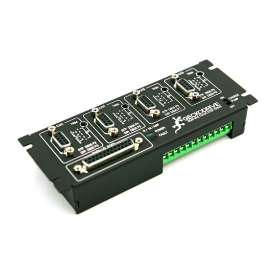
Page 2: Product Dimensions
PRODUCT DIMENSIONS PHYSICAL AND ELECTRICAL RATINGS Minimum Maximum Units Supply Voltage Motor Current Power Dissipation Short Circuit Trip Temperature °C Humidity Motor Inductance Input Frequency Step Pulse “0” Time Step Pulse “1” Time Direction Setup (Before step rising edge) Direction Setup (Hold after pulse rising edge) Signal Voltage Weight... - Page 3 Thank you for choosing to purchase the G540 4-Axis Drive System. If you are dissatisfied with it for any reason at all within 90 days of its purchase date, you may return it for a full refund provided it is cosmetically unmarred and undamaged electrically in any way.
-
Page 4: Step 8: Optional Connections
Your step pulse width must be at least 2uS wide and the pulse polarity for the step and direction signals are ACTIVE HIGH. STEP 6: TEST FUNCTIONS After you configure your CNC program it is time to test the G540 for functionality. You should be able to move all axes at this time. - Page 5 GECKODRIVE INC. assumes no liability for applications assistance or the purchaser’s product design. GECKODRIVE INC. does not warrant or represent that any license, either express or implied, is granted under any patent right, copyright or other intellectual property right of GECKODRIVE INC.
-
Page 6: Troubleshooting
PROBLEM: NO MOTOR HOLDING TORQUE SOLUTION: Verify that your motor is connected to the G540 with the DB9 connector and that it is wired as it says in the motor’s datasheet. Check the LED indicators to verify that power is being applied to the G540. Lastly, make sure that you have an appropriately sized current set resistor. - Page 7 4.) The only required connections for the G540 to run are a power supply and a normally closed emergency stop. If you get a fault at any time that will not clear, you can safely disconnect all wires but these and get a green LED with the...
- Page 8 OUTPUT and TERMINAL 12 (GND). The voltage can be the same as your G540 power supply or you can use a dedicated supply just for the OUTPUTs. Make sure the GND lines are tied together at the same point if you use a secondary supply.
- Page 9 G540 CUTOUT DIAGRAM...
- Page 10 This drawing is to scale. Use it as a guide for panel mounting your G540.
Need help?
Do you have a question about the G540 and is the answer not in the manual?
Questions and answers