Table of Contents
Advertisement
Advertisement
Table of Contents

Summary of Contents for REMBE EXKOP Mini
- Page 1 ®MINI EXKOP Explosion Isolation System page 1 of 25 GBB-EXKOM-08157/2...
-
Page 2: Table Of Contents
Table of contents 1. Operating and safety instructions Warning instructions Application limitation 2. Description General ®MINI Scope of EXKOP System Function 3. The QV II Quench Valve Installation notes Maintenance notes Technical data of QV II Quench Valve ®MINI 4. The EXKOP Safety Controller Installation notes Description of function... -
Page 3: Operating And Safety Instructions
Operating and safety instructions This manual must be read carefully and all instructions must be followed ®MINI before starting up the EXKOP safety system. Any modification or careless installation of the components can result in failure of the entire system. This can result in explosion propagation which can cause the destruction of the equipment. -
Page 4: Description
The explosion pressure and flame must be vented to the outside. This is not always possible inside buildings, but can only be realized with considerable physical modification and large expenditure. ® ® The REMBE Q-Rohr offers a flameless explosion venting device with dust retention allowing safe explosion venting indoors. ®MINI... -
Page 5: Scope Of Exkop
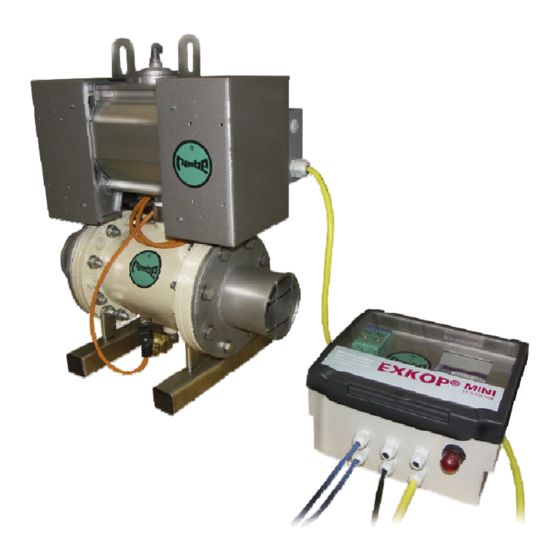
®MINI The EXKOP System normally consists of the following components: ® ® Explosion venting by Q-Rohr or REMBE triple section bursting discs with KFD2-ST2-Ex1.LB electronic display electronic ®MINI EXKOP Safety Controller with dynamic self monitoring function and internal data memory as well as an alarm-control... -
Page 6: Function
Normal production sequence The QV II Quench Valve (D) is open to the full pipe diameter with no pressure drop across the valve. ® QV II Quench Valve, REMBE bursting discs ® and Q-Rohr (B) ensure secondary protection in the event of a dust explosion without interrupting any production sequence. -
Page 7: The Qv Ii Quench Valve
The QV II Quench Valve Note: It is important that all information contained in this manual will be followed exactly in order to ensure a proper function of the valve. Installation notes The QV II Quench Valve must be installed in the connecting pipes between the vessels to be isolated. -
Page 8: Maintenance Notes
A pressure gauge arranged at the tank serves for visual monitoring of the available operating pressure. ® The pressure regulator and pressure switch, which settings are set at REMBE , may only be altered after consulting with our service department. All warranty claims ®... -
Page 9: Technical Data Of Qv Ii Quench Valve
Technical data of QV II Quench Valve Compressed-air connection: G1/4" at pressure reducer Compressed-air supply: Minimum 6 bar Compressed-air monitoring: Via pressure switch at tank, ®MINI signal to EXKOP Safety Controller Commissioning pressure: 5.5 bar Minimum operating pressure: 5.0 bar ®MINI Voltage supply: 24 V DC via EXKOP... -
Page 10: Description Of Function
4.2.1 Input modules The transformer isolated barrier KFD-ST2-Ex1.LB is used for signaling the status of ® ® the connected bursting discs or REMBE Q-Rohr . Upon activation of the Q-Rohr or ®MINI other safety devices, a signal is immediately sent to the EXKOP Safety Controller. -
Page 11: Internal Data Storage
4.2.3 Internal data storage A change of operating condition, faults and failures of the supply voltage are stored ®MINI internally in the EXKOP Safety Controller in chronological order. The storage capacity is sufficient for storing events over a period of one year. Storage takes place by means of ring storage, i.e. - Page 12 Schedule of different function ® MINI Input EXKOP terminal X1.16 X1.17 X1.18 Function 2 - 2 2x (1 - 1) 2 - 1 1 - 2 1 - 1 2 - 2 *) 2 - 2 *) 2 - 2 *) terminal +24VDC X4.16...
-
Page 13: Exkop ®Mini
®MINI 4.3.1 EXKOP Safety Controller – operation and wiring ® The EXKOP Safety Controller controls the connected input and output modules automatically. A manual handling is only necessary during the initiation and test run. ®MINI The power supply of the EXKOP Safety Controller must be connected to a 4-pole terminal of the CPU-Modules at the clamp + and –... - Page 14 The output status will be shown through yellow LED’s as follows: Output #1 Control Valve QV#1 Active = LED on Output #2 Control Valve QV#1 Active = LED on Output #3 Air Valve QV#1 Active = LED on Output #4 Air Valve QV#1 Active = LED on Output #5...
-
Page 15: Function Check
®MINI 4.3.3 EXKOP Safety Controller – initialization ®MINI After switching on the operating voltage, the EXKOP Safety Controller conducts a self test. All internal and external signals will be checked. If LED’s of the KFD2-ST2- Ex2.LB-Electronic lights “green” and pressure inside the tank of QV II Quench Valve ®MINI is built up, the EXKOP Safety Controller will be armed by pressing the Reset... -
Page 16: Transformer Isolated Barrier Kfd2-St2-Ex1.Lb
Transformer isolated barrier KFD2-ST2-Ex1.LB ® Monitoring of Q-Rohr and triple section bursting discs or other indicators is carried out by the transformer isolated barrier KFD2-ST2-Ex1.LB electronic. Three integrated LED's serve for status indication: Green LED lights: Power supply is connected to the relay = no fault Yellow LED lights: Output signal = sensor ok = save status Yellow LED dark:... - Page 17 The input of the KFD2-ST2-Ex1.LB electronic has to be connected to the terminals ®MINI #1 and #2 in the junction box and in the EXKOP Safety Controller at the terminals according to the terminal diagram. The signaling unit of the bursting disc or ®...
-
Page 18: Technical Data
Technical data ® ® ® ® Safety Controller ®MINI EXKOP Electronic control module for high speed monitoring of explosion events and activation of QVII Quench Valves. Self monitoring Safety Controller with internal data storage. Status report via display Supply: 24 VDC Power consumption: approx. - Page 19 ®MINI EXKOP Explosionsentkopplungssytem Explosion isolation system Betriebstagebuch / log book Anlage Nr. / Facility no: _________________ von / from ......... bis / till ......... Satz-Nr. / Datum / Zeit / Ereignis / Name / Unterschrift / file no. date time event name signature...
- Page 20 Installation Instructions for QV II Quench Valve Preparation of installation place Pressure The pipe work has to be fitted with counter flanges reducing valve (preset) according to the mounting and installation manometer instructions. Mounting of the QV II Quench Valves Be sure to allow the counter flanges to cool after welding.
- Page 21 Vacuum conditions for QV Quench Valve If you expect vacuum conditions in the process a bypass to the QV Quench valve must be installed. The bypass eliminate differential pressure between the process and interior of the Quench seal. This bypass assures full bore opening of the Quench Valve.
- Page 22 page 22 of 25 GBB-EXKOM-08157/3...
- Page 23 page 23 of 25 GBB-EXKOM-08157/3...
- Page 24 page 24 of 25 GBB-EXKOM-08157/3...
- Page 25 page 25 of 25 GBB-EXKOM-08157/3...
Need help?
Do you have a question about the EXKOP Mini and is the answer not in the manual?
Questions and answers