Table of Contents

Related Manuals for SEW-Eurodrive Movigear Performance MGF**-DFC-C Series


Summary of Contents for SEW-Eurodrive Movigear Performance MGF**-DFC-C Series
- Page 1 *25945475_0419* Drive Technology \ Drive Automation \ System Integration \ Services Operating Instructions Mechatronic Drive Unit ® MOVIGEAR performance MGF..-DFC-C (PROFINET IO, EtherNet/IP™, Modbus TCP, POWERLINK) Edition 04/2019 25945475/EN...
- Page 2 SEW-EURODRIVE—Driving the world...
-
Page 3: Table Of Contents
Table of contents Table of contents General information........................ 6 About this documentation .................... 6 Other applicable documentation .................. 6 Structure of the safety notes ................... 6 Decimal separator in numerical values ................ 7 Rights to claim under limited warranty ................ 7 Product names and trademarks.................. 8 Copyright notice ...................... 8 Safety notes .......................... - Page 4 Table of contents 4.10 Torque arm ........................ 60 4.11 Tightening torques ...................... 62 Electrical installation...................... 65 Installation planning taking EMC aspects into account.......... 65 Equipotential bonding at the connection box .............. 67 Installation instructions.................... 67 Installation topology (example: standard installation) ........... 74 Terminal assignment..................... 75 Connection diagram...................... 78 Cable routing and cable shielding................. 79 EMC cable glands...................... 82 Plug connectors ...................... 83...
- Page 5 Table of contents Determining the operating hours................. 282 Inspection and maintenance intervals................. 283 Lubricant change intervals .................. 285 Inspection and maintenance work ................ 286 Project planning........................ 294 10.1 Preliminary information .................... 294 10.2 Drive selection data .................... 295 ® 10.3 MOVIGEAR performance .................. 296 ® 10.4 DynaStop – The electrodynamic deceleration function .......... 304 Technical data and dimension sheets ................
-
Page 6: General Information
General information About this documentation General information About this documentation The current version of the documentation is the original. This documentation is an integral part of the product. The documentation is intended for all employees who perform work on the product. Make sure this documentation is accessible and legible. -
Page 7: Decimal Separator In Numerical Values
General information Decimal separator in numerical values Meaning of the hazard symbols The hazard symbols in the safety notes have the following meaning: Hazard symbol Meaning General hazard Warning of dangerous electrical voltage Warning of hot surfaces Warning of risk of crushing Warning about suspended load Warning of automatic restart 1.3.3... -
Page 8: Product Names And Trademarks
General information Product names and trademarks Product names and trademarks The brands and product names in this documentation are trademarks or registered trademarks of their respective titleholders. Copyright notice © 2019 SEW‑EURODRIVE. All rights reserved. Unauthorized reproduction, modifica- tion, distribution or any other use of the whole or any part of this documentation is strictly prohibited. -
Page 9: Safety Notes
Safety notes Preliminary information Safety notes Preliminary information The following general safety notes serve the purpose of preventing injury to persons and damage to property. They primarily apply to the use of products described in this documentation. If you use additional components, also observe the relevant warning and safety notes. -
Page 10: Designated Use
Safety notes Designated use Specialist for elec- Any electrotechnical work may only be performed by electrically skilled persons with a trotechnical work suitable education. Electrically skilled persons in the context of this documentation are persons familiar with electrical installation, startup, troubleshooting, and maintenance of the product who possess the following qualifications: •... -
Page 11: Transportation
Safety notes Transportation Transportation Inspect the shipment for damage as soon as you receive the delivery. Inform the ship- ping company immediately about any damage. If the product is damaged, it must not be assembled, installed or started up. Observe the following notes when transporting the device: •... -
Page 12: Installation/Assembly
Safety notes Installation/assembly Installation/assembly Ensure that the product is installed and cooled according to the regulations in the doc- umentation. Protect the product from strong mechanical strain. The product and its mounting parts must never protrude into the path of persons or vehicles. Ensure that components are not deformed and insulation spaces are not changed, particularly during transportation and handling. -
Page 13: Startup/Operation
Safety notes Startup/operation 2.9.1 Stationary application Necessary preventive measure for the product is: Type of energy transfer Preventive measure Direct power supply • Ground connection 2.9.2 Regenerative operation The drive is operated as a generator due to the kinetic energy of the system/machine. Before opening the connection box, secure the output shaft against rotation. - Page 14 Safety notes Magnetic fields Observe DGUV (German Social Accident Insurance) regulation 15 – "Electromagnetic fields" for use in industrial workplaces. In other countries, the corresponding national and local regulations and provisions must be complied with. ® Operating Instructions – MOVIGEAR performance...
-
Page 15: Unit Structure
Unit structure Drive unit MOVIGEAR® performance Unit structure Drive unit MOVIGEAR ® p erformanc ® Drive unit MOVIGEAR performance ® MOVIGEAR performance drive units are made up of the 3 core components gear unit, motor, and drive electronics. These 3 core components are included in one die- cast aluminum housing (see following figure). -
Page 16: Shaft Designs
Unit structure Shaft designs Shaft designs ® MOVIGEAR performance is available with the following shaft variants: ® 3.2.1 MOVIGEAR performance with hollow shaft and keyway (MGFA..-..-C) ® The following figure shows a MOVIGEAR performance unit with hollow shaft and key- way: 25331854475 ®... -
Page 17: Housing Mounting
Unit structure Housing mounting Housing mounting 3.3.1 Torque arm (MGF.T.-..-C) ® The following figure shows the torque arm for MOVIGEAR performance: 25331847179 ® Operating Instructions – MOVIGEAR performance... - Page 18 Unit structure Housing mounting 3.3.2 Housing with threads (MGF.S-..-C) WARNING Improper installation of the drive unit without torque arm. Severe or fatal injuries. • Only mount the drive units to the plant structure together with a torque arm. In- stallation without a torque arm is not permitted. The following figure shows the design "housing with threads"...
-
Page 19: Threads For Protective Cover
Unit structure Threads for protective cover Threads for protective cover NOTICE Impermissible use of the threads. Damage to the drive unit. • The threads may only be used for other applications after consultation with SEW‑EURODRIVE. • SEW‑EURODRIVE assumes no guarantee or liability for resulting product dam- ages. -
Page 20: Cable Entry Position
Unit structure Cable entry position Cable entry position ® The following cable entries are possible for MOVIGEAR performance MGF..-...-C drive units: • Position X + 1 + 2 + 3 – X: 2 x M25 x 1.5 + 2 x M16 x 1.5 – 1: 1 x M16 x 1.5 (only for option /PE) – 2: 2 x M25 x 1.5 + 2 x M16 x 1.5 – 3: 2 x M25 x 1.5 + 2 x M16 x 1.5 3.5.1 Overview The following figure shows the possible cable entries:... -
Page 21: Nameplate Position
Unit structure Nameplate position Nameplate position ® The following nameplate positions are possible for MOVIGEAR performance and ® MOVIGEAR classic: • • • 3 (standard position) 3.6.1 Overview The following figure shows the possible positions: 76646 Bruchsal/Germany eff% 89.0 MGFAS2-DFC-C/DI/AZ1Z/BW1 ru ch sa l/G er m... -
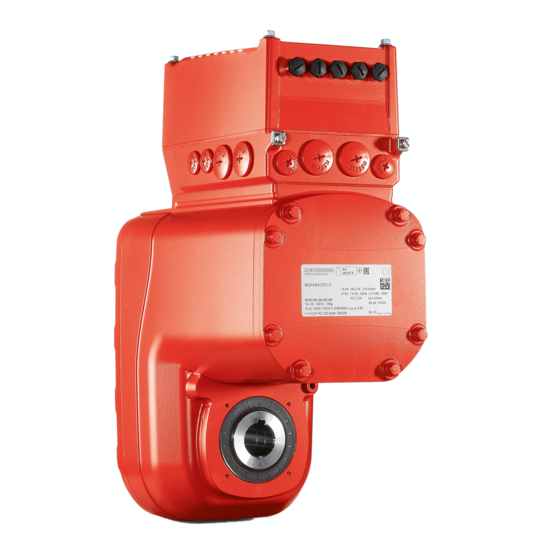
Page 22: Example Nameplate And Type Designation Of The Drive Unit
Unit structure Example nameplate and type designation of the drive unit Example nameplate and type designation of the drive unit 3.7.1 Nameplate ® The following figure gives an example of a nameplate for MOVIGEAR performance. For the structure of the type designation, refer to the chapter "Type designation". 76646 Bruchsal/Germany eff% 89.0 MGFAS2-DFC-C/DI/AZ1Z/DSP/IV/BW... - Page 23 Unit structure Example nameplate and type designation of the drive unit Size 2 = Torque class 200 Nm 4 = Torque class 400 Nm – DFC Communication variant DFC = Direct Fieldbus Communication – ® MOVIGEAR version ® DSP MOVIGEAR option XT = Increased torque (only with size 4) ®...
-
Page 24: Examples For The Optional Nameplate "Electrical Regulations Ul/Ce" (In Preparation)
Unit structure Examples for the optional nameplate "Electrical regulations UL/CE" (in preparation) Examples for the optional nameplate "Electrical regulations UL/CE" (in preparation) The following figure shows an example of the optional nameplate for drive units accor- ding to the electrical regulations UL/CE: Additional information UL-relevant data EURODRIVE 01.7244152929.0001.18... -
Page 25: Electronics
Unit structure Electronics 3.10 Electronics 3.10.1 Electronics cover (inside) and connection box The following figure shows the connection box and the bottom side of the electronics cover: [14] [15] [14] [15] [14] [15] [14] [13] [12] [11] [10] 9007224383194123 Cable glands Connection box Line connection L1, L2, L3 Braking resistor connection... - Page 26 Unit structure Electronics 3.10.2 Electronics cover (outside) The following figure shows one of the electronics cover designs using one size as an example: 25131167371 LED displays Plug connector ® Operating Instructions – MOVIGEAR performance...
-
Page 27: Example Nameplate And Type Designation Of Electronics
Unit structure Example nameplate and type designation of electronics 3.11 Example nameplate and type designation of electronics 3.11.1 Nameplate The following figure shows an example of the nameplate for the connection unit and the electronics cover. For the structure of the type designation, refer to the chapter "Type designation of the electronics cover". - Page 28 Unit structure Example nameplate and type designation of electronics Power section design EMC 0 = Basic interference suppression Connection type 3 = 3-phase – Version – Device variant 0 = Standard (process data communication) E = CiA402 device profile (DS402) Technology and application level 0.
-
Page 29: Example Nameplate And Type Designation Of Connection Unit
Unit structure Example nameplate and type designation of connection unit 3.12 Example nameplate and type designation of connection unit 3.12.1 Nameplate The following figure gives an example of a nameplate of the connection unit. For the structure of the type designation, refer to the chapter "Type designation of the connec- tion unit". -
Page 30: Mechanical Installation
Mechanical installation Installation notes Mechanical installation Installation notes INFORMATION Adhere to the safety notes during installation. WARNING Improper installation/disassembly of drive unit and mount-on components. Serious injuries. • Adhere to the notes about installation and disassembly. • Before releasing shaft connections, make sure that there are no active torsional moments present (tensions within the system). -
Page 31: Required Tools And Resources
Mechanical installation Required tools and resources Required tools and resources • Set of wrenches, set of screwdrivers, set of socket wrenches • Torque wrench • Mounting device • Compensation elements (shims and spacing rings), if necessary • Fasteners for output elements ®... -
Page 32: Setting Up The Drive Unit
Mechanical installation Setting up the drive unit Setting up the drive unit 4.4.1 Notes • Only mount the drive units to the plant structure together with a torque arm. Install- ation without a torque arm is not permitted. • Clean the shaft ends thoroughly to ensure they are free of anti-corrosion agents (use a commercially available solvent). - Page 33 Mechanical installation Setting up the drive unit Installing the electronics cover • Use only electronics covers that match the size. • Be careful not to tilt the electronics cover when placing it on the connection box: 25337980043 Minimum installation clearance Note the minimum installation clearance (see following figure) required to remove the electronics cover.
- Page 34 Mechanical installation Setting up the drive unit 4.4.4 Derating depending on the installation altitude The following diagram shows the factor f (according to IEC 60034-1:2017, Table 12) by which the thermal motor torque has to be reduced depending on the installation altitude H. Observe the additional chapter "Technical data and dimension drawings" > "Derating depending on the ambient temperature".
- Page 35 Mechanical installation Setting up the drive unit 4.4.6 Gear unit venting Drive units with installed breather valve Except for the mounting position M3, SEW‑EURODRIVE delivers all drive units ordered for a specific mounting position with a breather valve that is activated and in- stalled according to the specific mounting position.
- Page 36 Mechanical installation Setting up the drive unit Example: Mounting position M1 Example: Mounting position M1 25343401227 ® Operating Instructions – MOVIGEAR performance...
- Page 37 Mechanical installation Setting up the drive unit Activating the breather valve After installing the breather valve, activate it as follows. For designs with the breather valve screwed in: Check whether the breather valve is activated. If not, you have to re- move the transport fixture of the breather valve before you start up the drive unit.
- Page 38 Mechanical installation Setting up the drive unit 4.4.7 Pressure compensation on electronics (option /PE) Designs with included pressure compensation fitting (option /PE) On designs with an included pressure compensation fitting (option /PE), install the fit- ting depending on the mounting position used. The tightening torque is 4.0 Nm. The following table shows the installation positions depending on the mounting posi- tions: Mounting positions...
-
Page 39: Shaft-Mounted Gear Unit With Keyway
Mechanical installation Shaft-mounted gear unit with keyway * Mounting position M3 is only possible with the option "integrated pressure com- pensation /PG". Observe the documentation "Integrated Pressure Compensation (Option /PG)". Shaft-mounted gear unit with keyway INFORMATION Observe the design notes in chapter "Technical data and dimension sheets" for the customer shaft design. -
Page 40: Customer Shaft With Contact Shoulder
Mechanical installation Shaft-mounted gear unit with keyway 2. Mount the shaft and secure it axially (using a mounting device makes installation easier). The three mounting types are described below: ð 2A: Standard scope of delivery 9007220768364043 Short retaining screw (standard scope of delivery) Lock washer Washer Retaining ring... - Page 41 Mechanical installation Shaft-mounted gear unit with keyway 9007220768369931 Retaining screw Lock washer Washer Retaining ring Spacer tube Customer shaft without contact shoulder 3. Tighten the retaining screw with the specified torque (see chapter "Tightening torques for retaining screws"). 9007220768463371 4.5.2 Tightening torques for retaining screws Drive Screw...
- Page 42 Mechanical installation Shaft-mounted gear unit with keyway INFORMATION For information on the SEW‑EURODRIVE assembly/disassembly kit, see chapter "Technical data and dimension sheets" > "Design notes". The following description only applies when the drive is assembled using the SEW‑EURODRIVE assembly/disassembly kit (see previous description, points 2B or 2C).
- Page 43 Mechanical installation Shaft-mounted gear unit with TorqLOC® (customer shaft without contact shoulder) Shaft- mounted gear unit with TorqLOC® (customer shaft without contact shoulder) ® Shaft-mounted gear unit with TorqLOC (customer shaft without contact shoulder) 1. Clean the customer shaft and the inside of the hollow shaft. Ensure that all traces of grease or oil are removed.
- Page 44 Mechanical installation Shaft-mounted gear unit with TorqLOC® (customer shaft without contact shoulder) 5. Push the gear unit onto the customer shaft. 9007220783649163 6. Mount the torque arm onto the system structure/holding fixture (do not tighten the screws). 9007220783651595 ® Operating Instructions – MOVIGEAR performance...
- Page 45 Mechanical installation Shaft-mounted gear unit with TorqLOC® (customer shaft without contact shoulder) 7. Push the bushing into the gear unit up to the stop. 9007220783654027 8. Push the stop ring to the bushing. Mark the position of the stop ring. 9007220783656459 ®...
- Page 46 Mechanical installation Shaft-mounted gear unit with TorqLOC® (customer shaft without contact shoulder) 9. Remove the torque arm from the holding fixture/system structure. 9007220783658891 10. Pull the gear unit off the customer shaft until the stop ring is accessible for fasten- ing.
- Page 47 Mechanical installation Shaft-mounted gear unit with TorqLOC® (customer shaft without contact shoulder) 18014420037795339 13. Push the bushing and the gear unit onto the customer shaft up to the fixed stop ring. 9007220783619979 14. Mount the torque arm onto the system structure/holding fixture again (do not tighten the screws).
- Page 48 Mechanical installation Shaft-mounted gear unit with TorqLOC® (customer shaft without contact shoulder) 15. Make sure that all screws are loosened and slide the shrink disk onto the hollow shaft. 18014420038365835 16. Slide the counter bushing onto the customer shaft and into the hollow shaft. 18014420038368267 17.
- Page 49 Mechanical installation Shaft-mounted gear unit with TorqLOC® (customer shaft without contact shoulder) 19. Make sure that the customer shaft is seated in the counter bushing. 18014420038373131 20. Tighten the screws of the shrink disk only hand-tight and ensure that the outer rings of the shrink disk are parallel.
- Page 50 Mechanical installation Shaft-mounted gear unit with TorqLOC® (customer shaft without contact shoulder) 22. After installation, make sure the remaining gap s between the outer rings of the shrink disks is > 0 mm. ð The remaining gap between counter bushing and hollow shaft end as well as bushing and stop ring must be > 0 mm.
- Page 51 Mechanical installation Shaft-mounted gear unit with TorqLOC® (customer shaft with contact shoulder) Shaft- mounted gear unit with TorqLOC® (customer shaft with contact shoulder) ® Shaft-mounted gear unit with TorqLOC (customer shaft with contact shoulder) 1. Clean the customer shaft and the inside of the hollow shaft. Ensure that all traces of grease or oil are removed.
- Page 52 Mechanical installation Shaft-mounted gear unit with TorqLOC® (customer shaft with contact shoulder) ® 4. Apply NOCO fluid on the bushing and spread thoroughly. 21528996363 5. Push the gear unit onto the customer shaft. 9007220783739787 6. Make sure that all screws are loosened and slide the shrink disk onto the hollow shaft.
- Page 53 Mechanical installation Shaft-mounted gear unit with TorqLOC® (customer shaft with contact shoulder) 7. Slide the counter bushing onto the customer shaft and into the hollow shaft. 18014420038485643 8. In the case of a gear unit with shaft shoulder, mount the shrink disk at the shaft shoulder up to the stop.
- Page 54 Mechanical installation Shaft-mounted gear unit with TorqLOC® (customer shaft with contact shoulder) 11. Tighten the screws of the shrink disk only hand-tight and ensure that the outer rings of the shrink disk are parallel. // 0.006 x D A 18014420038463755 12.
- Page 55 Mechanical installation Shaft-mounted gear unit with TorqLOC® (customer shaft with contact shoulder) 14. The remaining gap between counter bushing and hollow shaft end must be > 0 mm. > 0 mm > 0 mm 21528986635 15. Mount the torque arm and tighten it securely; observe the chapter "Torque arm". 9007220783730059 ®...
-
Page 56: Shaft-Mounted Gear Unit With Torqloc - Disassembly, Cleaning, Lubrication
Mechanical installation Shaft-mounted gear unit with TorqLOC® – disassembly, cleaning, lubrication Shaft- mounted gear unit with TorqLOC® – d isassembl y, cleaning, lubrication ® Shaft-mounted gear unit with TorqLOC – disassembly, cleaning, lubrication 4.8.1 Removal notes WARNING Risk of burns due to hot surfaces. Serious injuries. - Page 57 Mechanical installation Shaft-mounted gear unit with TorqLOC® – disassembly, cleaning, lubrication 4.8.2 Cleaning and lubrication There is no need to dismantle removed shrink disks before they are reinstalled. Clean and lubricate the shrink disk if it is dirty. Lubricate the tapered surfaces with one of the following solid lubricants: Lubricant (Mo S2) Sold as Molykote 321 (lube coat)
-
Page 58: Installing The Protective Cover
Mechanical installation Installing the protective cover Installing the protective cover WARNING Risk of injury caused by rapidly moving output elements. Serious injuries. • Disconnect the drive unit from the power supply and safeguard it against uninten- tional power up before you start working on it. •... - Page 59 Mechanical installation Installing the protective cover 3. The following figure shows the installed safety cover. OPEN CLOSE OPEN CLOSE 9007220768944523 4. Fasten the locking device in the bore provided for this purpose using the enclosed screw and serrated lock washer. The permitted tightening torque for the screw M4x10 is 3.3 Nm.
-
Page 60: Torque Arm
Mechanical installation Torque arm 4.10 Torque arm NOTICE Improper assembly may damage the drive unit. Possible damage to property. • Do not place torque arms under strain during installation. • Always use bolts of quality 8.8 to fasten torque arms. INFORMATION If required, the necessary bolts can be included in the delivery. - Page 61 Mechanical installation Torque arm 4.10.1 Installation options The following figure shows the possible mounting positions of the torque arm: 25347868811 Torque arm axis length Bore diameter Torque arm thickness Bush with bearings on both ends The following table shows the required tightening torques: Drive Torque arm Tightening torque...
-
Page 62: Tightening Torques
Mechanical installation Tightening torques 4.11 Tightening torques WARNING Risk of burns due to hot surfaces. Serious injuries. • Let the devices cool down before touching them. 4.11.1 Blanking plugs Tighten the plastic blanking plugs included in the delivery by SEW‑EURODRIVE with 2.5 Nm: Example The following figure shows an example. - Page 63 Mechanical installation Tightening torques Screw fitting Part Content Size Outer Tighten- number cable dia- meter torque EMC cable glands 18216366 10 pcs M16 x 1.5 5 to 9 mm 4.0 Nm (stainless steel) 18216382 10 pcs M25 x 1.5 11 to 7.0 Nm 16 mm The cable retention in the cable gland must withstand the following removal force of the cable from the cable gland:...
- Page 64 Mechanical installation Tightening torques ® 4.11.3 MOVIGEAR electronics cover Proceed as follows when installing the electronics cover: Insert the screws and tighten them in diametrically opposite sequence step by step with a tightening torque of 6.0 Nm. 25351078155 ® Operating Instructions – MOVIGEAR performance...
-
Page 65: Electrical Installation
Electrical installation Installation planning taking EMC aspects into account Electrical installation INFORMATION Adhere to the safety notes during installation. Installation planning taking EMC aspects into account 5.1.1 Notes on arranging and routing installation components The correct operation of decentralized inverters depends on selecting the correct cables, providing correct grounding, and on a properly functioning equipotential bond- ing. - Page 66 Electrical installation Installation planning taking EMC aspects into account 5.1.4 Equipotential bonding Regardless of the PE connection, it is essential that low-impedance, HF-capable equipotential bonding is provided (see also EN 60204-1 or DIN VDE 0100-540): • Provide for a connection over a wide area between the device and the mounting rail.
-
Page 67: Equipotential Bonding At The Connection Box
Electrical installation Equipotential bonding at the connection box Equipotential bonding at the connection box Another option for HF-capable equipotential bonding at a connection box is the follow- ing cable gland with M6 stud bolt: 3884960907 Tightening torque Tightening torque Part number of the cable gland of the M6 nut for stud bolt... - Page 68 Electrical installation Installation instructions 5.3.2 Connecting supply system cables • The nominal voltage and frequency of the device must correspond with the data of the supply system. • Dimension the cable cross section according to the input current I for nominal line power (see the chapter "Technical data and dimension sheets").
- Page 69 Electrical installation Installation instructions 5.3.4 Activating line terminals X1 Adhere to the following sequence when actuating the line terminals: Line terminals X1 (the following figure shows a schematic illustration) 25649924107 5.3.5 Activating terminals X3 for the braking resistor Adhere to the following sequence when you activate the terminals X3 for the braking resistor: Terminals X3 for the braking resistor (the following figure shows a schematic illustration)
- Page 70 Electrical installation Installation instructions 5.3.6 Activating control terminals X9 Adhere to the following sequence when actuating the X9 control terminals: X9 control terminals (the following figure shows a schematic illustration) 25657187979 5.3.7 Residual current device WARNING No protection against electric shock if an incorrect type of residual current device is used.
- Page 71 Electrical installation Installation instructions 5.3.9 Notes on PE connection WARNING Electric shock due to incorrect connection of PE. Severe or fatal injuries. • The permitted tightening torque for the screw is 2.0 to 2.4 Nm. • Observe the following notes regarding PE connection. Make sure the lifting eye has been removed before you connect the PE cable.
- Page 72 Electrical installation Installation instructions [1] Forked cable lug suitable for M5 PE screws Leakage currents Earth-leakage currents ≥ 3.5 mA can occur during normal operation. In order to fulfill EN 61800-5-1, observe the following notes: • The protective earth (PE) connection must meet the requirements for systems with high earth-leakage currents.
- Page 73 Electrical installation Installation instructions 5.3.12 UL-compliant installation (in preparation) ® UL and cUL approval for the MOVIGEAR performance series is in preparation. ® Operating Instructions – MOVIGEAR performance...
-
Page 74: Installation Topology (Example: Standard Installation)
Electrical installation Installation topology (example: standard installation) Installation topology (example: standard installation) following figure shows basic installation topology with ® MOVIGEAR performance: Safety relay 24 V Supply system Controller Backup mode Back-up fuse/line protection Control cabinet level Field level DFC.0.. ®... -
Page 75: Terminal Assignment
Electrical installation Terminal assignment Terminal assignment WARNING Electric shock due to regenerative operation when the shaft is turning. Severe or fatal injuries. • Secure the output shaft against rotation when the electronics cover is removed. INFORMATION The terminals X3 for connecting the braking resistor can be connected to an optional, internal braking resistor. - Page 76 Electrical installation Terminal assignment Assignment Terminal Name Marking Function Brown Line connection, phase L1 – IN line terminals Black Line connection, phase L2 – IN Gray Line connection, phase L3 – IN 11 L1 Brown Line connection, phase L1 – OUT 12 L2 Black Line connection, phase L2 –...
- Page 77 Electrical installation Terminal assignment Assignment Terminal Name Marking Function 0V24_OUT – 0V24 reference potential engineering for DC 24 V auxiliary output interface CAN_L – CAN Low connection CAN_H – CAN High connection 24V_OUT – DC 24 V auxiliary output 1) in preparation The following figure shows the factory-installed jumpers at the X9 terminals: 11 12 13 14 21 22 23 24 9007221264582283...
-
Page 78: Connection Diagram
Electrical installation Connection diagram Connection diagram F11/F12/F13 MOVIGEAR ® performance MGF..-DFC-C Line terminals Braking resistor Engineering interface Fieldbus mini IO X4233_1 Fieldbus X4233_2 Digital inputs/outputs Control terminals 25571474187 Only for designs with electronics cover DFC.1.. (in preparation) Only for designs with electronics cover DFC.0.. Jumpers installed at the factory (only applicable to designs without plug connect- ors with STO function). -
Page 79: Cable Routing And Cable Shielding
Electrical installation Cable routing and cable shielding Cable routing and cable shielding 5.7.1 Accessory bag with installation equipment (part number 18241395) INFORMATION For some installation variants, you do not need all the parts of the accessory kit. ® Each MOVIGEAR drive unit is delivered with an accessory bag that contains installa- tion equipment for cable shielding (except for when the order didn't include all possible connections as plug connector design):... - Page 80 Electrical installation Cable routing and cable shielding 5.7.2 General installation options The following figure shows the general installation options. The following chapters show common examples and contain important notes on cable selection and cable routing. 25205817355 ® Operating Instructions – MOVIGEAR performance...
- Page 81 Electrical installation Cable routing and cable shielding 5.7.3 Installation with separately routed Ethernet cable Notes on cable routing and shielding – Recommended cable routing Note the following when routing and shielding the cables: • Cable selection – For cable selection, note the chapter "Technical data and dimension sheets/ specification of recommended Ethernet connection cable"...
-
Page 82: Emc Cable Glands
Electrical installation EMC cable glands EMC cable glands 5.8.1 Cable shielding (alternative) – Control cables As an alternative to using shield clamps for control cables (STO, binary signals), you can use EMC cable glands, which are available as an option, to connect the shield. 25216680843 5.8.2 Assembly of EMC cable glands... -
Page 83: Plug Connectors
Electrical installation Plug connectors Plug connectors 5.9.1 Representation of connections The wiring diagrams of the plug connectors depict the contact end of the connections. 5.9.2 Designation key The designation of plug connectors is specified according to the following key: Terminal Group 1 = Power input 2 = Power output... - Page 84 Electrical installation Plug connectors 5.9.3 Connection cables INFORMATION For more information on cable types, refer to the chapter "Technical data". Connection cables are not included in the delivery. Prefabricated cables for connecting SEW‑EURODRIVE components can be ordered. For each connection, the available prefabricated cables are listed. Specify the part number and length of the required cable in your order.
- Page 85 Electrical installation Plug connectors Using third-party cables with plug connectors If third-party cables are used – even if these cables are technically adequate – SEW‑EURODRIVE does not accept any liability and cannot guarantee unit properties or functions. When using third-party cables to connect the device and/or device components, make sure to comply with all applicable national regulations.
- Page 86 Electrical installation Plug connectors 5.9.4 Plug connector positions of the drive unit The following figure shows possible plug connector positions: X1523 X5505 X5504 X2313 X4141 X4141 X2313 X5504 X5505 X1523 X1203_1 X1203_2 X1203_1 X1203_2 X1203_1 X1203_1 X5505 X5504 X1203_2 X1203_1 X1523 X2313 X1203_1...
- Page 87 Electrical installation Plug connectors Plug connector Not together at a position with the Designation Coding ring/ Function Position plug connector: color • X5505 X1523 Light gray DC 24 V input backup voltage X, 2 or 3 • X4141 X2313 Light gray DC 24 V output backup voltage X, 2 or 3 •...
- Page 88 Electrical installation Plug connectors 5.9.5 Plug connector positions at the electronics cover The following figure shows the plug connector positions: X5133_1 X5133_2 X5133_3 X4233_1 X4233_2 18014420217585035 Plug connector Function X5133_1 Digital inputs DI01 and DI02 X5133_2 Digital inputs DI03 and DI04 X5133_3 Digital inputs/outputs DIO01 and DIO02 X4233_1...
- Page 89 Electrical installation Plug connectors 5.9.6 Plug connector variants M12 plug connector M12 plug connectors at the connection box are pre-installed so they match the con- nection cables provided by SEW‑EURODRIVE. Customers can adjust the orientation of plug connectors if required. The following figure shows a schematic illustration with the permitted tightening torques: 6 Nm...
- Page 90 Electrical installation Plug connectors M23 plug connector CAUTION Possible damage of the right-angle connector when rotated without mating con- nector. Irreparable damage to the thread, damage to the sealing surface. • Do not use pliers to adjust the right-angle connector before connecting it. CAUTION Loss of the guaranteed degree of protection.
- Page 91 Electrical installation Plug connectors ® Example of MOVIGEAR performance 2 mm 3 Nm 9007224476469899 "Straight" design "Angled" design The tightening torque for the union nut is 3 Mn. You can order suitable tools from TE Connectivity - Intercontec products using the following order number: •...
- Page 92 Electrical installation Plug connectors 5.9.7 Using plug connectors assembled by yourself The power plug connectors for assembling connection cables yourself, and the corres- ponding assembly tool set is available for order from TE Connectivity - Intercontec products. Contact TE Connectivity - Intercontec products if the order designation is not available in the online order system of Intercontec.
-
Page 93: Optional Plug Connector Assignment
Electrical installation Optional plug connector assignment 5.10 Optional plug connector assignment WARNING Electric shock when disconnecting or connecting voltage-carrying plug connectors. Severe or fatal injuries • Switch off the line voltage. • Never plug or unplug plug connectors while they are energized. 5.10.1 X1203_1 and X1203_2: AC 400 V connection The following table shows information about this connection:... - Page 94 Electrical installation Optional plug connector assignment Connection cables The following tables list the cables available for this connection: Cable cross section 1.5 mm Connection cable Conformity/ Cable type Length/in- Cable part num- stallation cross sec- type tion/operat- ing voltage ® HELUKABEL Variable 1.5 mm...
- Page 95 Electrical installation Optional plug connector assignment Connection cable Conformity/ Cable type Length/in- Cable part num- stallation cross sec- type tion/operat- ing voltage ® HELUKABEL Variable 2.5 mm ® MULTIFLEX 18153275 – 512 AC 500 V M23, coding M23, coding ring: black, ring: black, male male ®...
- Page 96 Electrical installation Optional plug connector assignment Cable cross section 4.0 mm Connection cables Conformity/ Cable type Length/in- Cable part num- stallation cross-sec- type tion/operat- ing voltage ® HELUKABEL Variable 4 mm ® TOPFLEX – 18127487 600-PVC AC 500 V 18133975 M23, coding M23, coding ring: black, ring: black, male...
- Page 97 Electrical installation Optional plug connector assignment Connection cables Conformity/ Cable type Length/in- Cable part num- stallation cross-sec- type tion/operat- ing voltage ® HELUKABEL Variable 4 mm ® TOPFLEX – 18133983 611-PUR AC 500 V (Halogen-free) Open M23, coding ring: black, male ® HELUKABEL Variable 4 mm –...
- Page 98 Electrical installation Optional plug connector assignment Connection of cables with open end The following table shows the conductor assignment of the cables with the following part numbers: Part number Signal name Core color Identification Prefabrication 18180094 Black 18127479 Black Cut off 18133967 Black 18153283...
- Page 99 Electrical installation Optional plug connector assignment 5.10.2 X5504: STO (3 cores) WARNING No safe disconnection of the device. Severe or fatal injuries. • Do not use the 24 V output (pins 1 and 3) for safety-related applications. • Only jumper the STO connection with 24 V if the device does not have to fulfill any safety function.
- Page 100 Electrical installation Optional plug connector assignment Connection cables INFORMATION Use only shielded cables for this connection and only suitable plug connectors that connect the shield with the device in an HF-capable manner. The following table provides an overview of the cables available for this connection: Connection cable Conformity/ Cable type...
- Page 101 Electrical installation Optional plug connector assignment Connection cable Conformity/ Cable type Length/in- Cable part num- stallation cross sec- type tion/operat- ing voltage CE/UL: igus chainflex Variable 4 x 0.5 mm CF78.UL 28110994 DC 60 V M12, -5‑pin, M12, 5‑pin, A‑coded, fe- A‑coded, male male CE/UL: igus chainflex...
- Page 102 Electrical installation Optional plug connector assignment Connection of cables with open end The following tables show the conductor assignment of cables with the following part numbers: Part number Signal name Core color Identification Prefabrication 28110978 24V_OUT – – 28110943 F_STO_P2 White –...
- Page 103 Electrical installation Optional plug connector assignment 5.10.3 X5505: STO (3 cores) WARNING Disabling of the safety-related disconnection of further devices due to parasitic voltages when using an STO jumper plug. Severe or fatal injuries. • Only use the STO jumper plug when all incoming and outgoing STO connections have been removed from the device.
- Page 104 Electrical installation Optional plug connector assignment Connection cables INFORMATION Use only shielded cables for this connection and only suitable plug connectors that connect the shield with the device in an HF-capable manner. The following table provides an overview of the cables available for this connection: Connection cable Conformity/ Cable type...
- Page 105 Electrical installation Optional plug connector assignment Connection cable Conformity/ Cable type Length/in- Cable part num- stallation cross sec- type tion/operat- ing voltage CE/UL: igus chainflex Variable 4 x 0.5 mm CF78.UL 28110994 DC 60 V M12, -5‑pin, M12, 5‑pin, A‑coded, fe- A‑coded, male male CE/UL: igus chainflex...
- Page 106 Electrical installation Optional plug connector assignment Part number Signal name Core color Identification Prefabrication 28117816 24V_OUT – 28111044 F_STO_P2 Black 0V24_OUT – – Cut off F_STO_P1 Black F_STO_M Black 1) Do not connect this core in the plug connector. ® Operating Instructions –...
- Page 107 Electrical installation Optional plug connector assignment 5.10.4 STO jumper plug (3-core) WARNING Safe disconnection of the device is not possible when using the STO jumper plug. Severe or fatal injuries. • Only use use the STO jumper plug if the device is not used to fulfill any safety function.
- Page 108 Electrical installation Optional plug connector assignment 5.10.5 X1523: DC 24 V backup voltage, input The following table shows information about this connection: Function 24 V backup voltage input Connection type M12, 5‑pin, male, L‑coded, color: light gray Connection diagram Assignment Name Function +24V/L1 DC 24 V input/L1 (for backup mode) 0V24/N2 0V24 reference potential/N2...
- Page 109 Electrical installation Optional plug connector assignment Connection cables The following table provides an overview of the cables available for this connection: Connection cable Conformity/ Cable type Length/in- Cable part num- stallation cross sec- type tion/operat- ing voltage CE/UL: HELUKABEL Variable 5 x 2.5 mm JZ-500 28114345...
- Page 110 Electrical installation Optional plug connector assignment 5.10.6 X2313: DC 24 V output backup voltage The following table shows information about this connection: Function DC 24 V output backup voltage Connection type M12, 5‑pin, female, L‑coded, color: light gray Connection diagram Assignment Name Function +24V/L1 DC 24 V output/L1 (for backup mode)
- Page 111 Electrical installation Optional plug connector assignment Connection cables The following table provides an overview of the cables available for this connection: Connection cable Conformity/ Cable type Length/in- Cable part num- stallation cross sec- type tion/operat- ing voltage CE/UL: HELUKABEL Variable 5 x 2.5 mm JZ-500 28114345...
- Page 112 Electrical installation Optional plug connector assignment 5.10.7 X4141: Engineering interface The following table shows information about this connection: Function Engineering interface (CAN) Connection type M12, 5‑pin, female, A‑coded, color: black Connection diagram Assignment Name Function Res. Reserved 24V_OUT DC 24 V auxiliary output 0V24_OUT 0V24 reference potential CAN_H...
- Page 113 Electrical installation Optional plug connector assignment Connection cables The following table provides an overview of the cables available for this connection: Connection cable Conformity/ Length/in- Operating part num- stallation voltage type Connection to interface adapter USM21A: 3.0 m DC 60 V 28111680 M12, 5‑pin, RJ10 A‑coded, male Connection to CBG..
-
Page 114: Plug Connector Assignment At The Electronics Cover
Electrical installation Plug connector assignment at the electronics cover 5.11 Plug connector assignment at the electronics cover 5.11.1 X5133_1: Digital inputs The following table shows information about this connection: Function Digital inputs Connection type M12, 5‑pin, female, A‑coded, color: black Connection diagram Assignment No. - Page 115 Electrical installation Plug connector assignment at the electronics cover 5.11.2 X5133_2: Digital inputs The following table shows information about this connection: Function Digital inputs Connection type M12, 5‑pin, female, A‑coded, color: black Connection diagram Assignment No. Name Function +24V DC 24 V sensor supply DI04 Sensor input DI04 0V24...
- Page 116 Electrical installation Plug connector assignment at the electronics cover 5.11.3 X5133_3: Digital inputs/outputs The following table shows information about this connection: Function Digital inputs/outputs Connection type M12, 5‑pin, female, A‑coded, color: black Connection diagram Assignment No. Name Function +24V DC 24 V sensor/actuator supply DIO02 Sensor input DIO02/actuator output DIO02 0V24...
- Page 117 Electrical installation Plug connector assignment at the electronics cover 5.11.4 X4233_1: Fieldbus/Ethernet interface, port 1 The following table shows information about this connection: Function Fieldbus/Ethernet interface, port 1 Connection type M12, 4‑pin, female, D‑coded, color: black Connection diagram Assignment No. Name Function Transmit line (+) Receive line (+)
- Page 118 Electrical installation Plug connector assignment at the electronics cover 5.11.5 X4233_2: Fieldbus/Ethernet interface, port 2 The following table shows information about this connection: Function Fieldbus/Ethernet interface, port 2 Connection type M12, 4‑pin, female, D‑coded, color: black Connection diagram Assignment No. Name Function Transmit line (+) Receive line (+)
-
Page 119: Pc Connection
Electrical installation PC connection 5.12 PC connection Connect the PC to the drive unit before you start the engineering software ® MOVISUITE You have several options to connect a PC to the drive unit. 5.12.1 Connection via interface adapter USM21A The USM21A interface adapter is used to connect the PC and the engineering inter- face of the device. - Page 120 Electrical installation PC connection Connection to X4141 (M12 at the connection box) The engineering interface X31 in the connection box of the drive unit is assigned to the internal wiring of plug connector X4141. X4141 9007224819186315 USB 2.0 connection cable (commercial, included in the delivery of USM21A) Interface adapter USM21A Connection cable RJ10/M12...
- Page 121 Electrical installation PC connection 6. Insert the RJ10 plug connector into plug connector X31 in the connection box. The following figure shows an example of the cable routing: X4141 X4141 9007225044813707 7. Plug the electronics cover onto the connection box. Screw on the electronics cover with 4 screws (tightening torque: 6 Nm).
- Page 122 Electrical installation PC connection Connection to X31 (RJ10 in the connection box) NOTICE Connector X31 provides a 24 V supply voltage for operating the connected options. Damage to connected options with low nominal voltage. • Only connect options with a nominal voltage of 24 V to connector X31, such as: –...
- Page 123 Electrical installation PC connection 5.12.2 Connection via Ethernet You can establish a connection between PC and device using Ethernet. The Ethernet connection allows you to access the implemented electronics web server. Connection to X4233_1 or X4233_2 (M12 at the electronics cover) (Only for designs with electronics cover DFC.0..) Ethernet X4233_1 X4233_2...
- Page 124 Electrical installation PC connection 5.12.3 Connection via CBG21A or CBG11A keypad (in preparation) Use the CBG21A or CBG11A keypad to connect the PC and the engineering interface of the device. The data is transferred according to the USB 2.0 standard. It is also possible to work with a USB 3.0 interface.
- Page 125 Electrical installation PC connection Connection to X31 (RJ10 in the connection box) NOTICE Connector X31 provides a 24 V supply voltage for operating the connected options. Damage to connected options with low nominal voltage. • Only connect options with a nominal voltage of 24 V to connector X31, such as: –...
-
Page 126: Startup
Startup Startup notes Startup Startup notes INFORMATION It is essential to comply with the safety notes during startup. WARNING Risk of injury due to missing or defective protective covers. Severe or fatal injuries. • Install the protective covers of the system according to the instructions. •... -
Page 127: Startup Requirements
Startup Startup requirements NOTICE Undercutting the minimum switch-off time of the line contactor. Irreparable damage to the inverter or unforeseen malfunctions. • You must observe a minimum switch-off time of 10 s after switching off the voltage supply. • Do not switch the voltage supply on or off more often than once per minute. INFORMATION •... -
Page 128: Dip Switches
Startup DIP switches DIP switches 6.3.1 Overview NOTICE Damage to the DIP switches caused by unsuitable tools. Possible damage to property. • To set the DIP switches, use only suitable tools, such as a slotted screwdriver with a blade width of no more than 3 mm. •... - Page 129 Startup DIP switches DIP switch S2 (PROFINET, EtherNet/IP™, Modbus TCP) The following table shows the functions of DIP switch S2: switch Meaning Local mode Reserved Reserved Reserved Local mode can be activated – – – in every drive state. Local mode can only be –...
- Page 130 Startup DIP switches 6.3.2 Description of the DIP switches DIP switch S1/1: Direction of rotation reversal (PROFINET, EtherNet/IP™, Modbus TCP) INFORMATION The direction of rotation is reversed depending on the setting of the DIP switch and of the parameter drive train 1 > Controller > Direction of rotation reversal.
- Page 131 Startup DIP switches DIP switch S1/3: Disabling speed monitoring (PROFINET, EtherNet/IP™, Modbus TCP) INFORMATION If the function of this DIP switch is disabled via parameter access, the last active set- ting is maintained. This DIP switch is used to disable speed monitoring. •...
-
Page 132: Startup Procedure
Startup Startup procedure Startup procedure ® Perform startup of the devices using the MOVISUITE engineering software of SEW‑EURODRIVE. 25882306443 The startup procedure is divided into segments. The following steps illustrate the start- up procedure for a device by way of an example. Drive train seg- ment Drive train... - Page 133 Startup Startup procedure PI configuration • Advanced PE configuration • FCB 05 Speed control Drive functions • FCB 06 Interpolated speed control • FCB 09 Positioning • FCB 10 Interpolated position control • FCB 12 Reference travel • FCB 01 Output stage inhibit Advanced drive functions •...
- Page 134 Startup Startup procedure 6.4.1 Checklist for startup The following checklist lists the necessary steps for complete startup. Step Startup step Finished Install the drive unit. ® Install the MOVI-C component. ® Start MOVISUITE Start up the drive train. Parameterize the setpoints. Parameterize the function blocks (FCBs).
-
Page 135: Process Data Assignment - Movikit Function Module "5Pd Velocity
Startup Process data assignment – MOVIKIT® function module "5PD Velocity" Process data assignment – M OVIKIT® function module "5PD Velocity" ® Process data assignment – MOVIKIT function module "5PD Velocity" ® In the standard design, the device is delivered with the MOVIKIT function module "5PD Velocity". -
Page 136: Disabling Dynastop For Startup Purposes
Startup Disabling DynaStop® for startup purposes Disabling DynaStop® for startup purposes ® Disabling DynaStop for startup purposes ® 6.6.1 Important notes on disabling DynaStop WARNING ® Removing the electronics cover will disable DynaStop Severe or fatal injuries. • If it is not permitted to deactivate the system, additional measures are required (e.g. - Page 137 Startup Disabling DynaStop® for startup purposes ® 6.6.2 Steps for disabling DynaStop INFORMATION ® For more information about the DynaStop function, refer to the chapters "Operation" and "Technical data and dimension sheets". ® Disabling DynaStop by removing the electronics cover ®...
-
Page 138: Operation
Operation Manual mode with MOVISUITE® Operation Manual mode with MOVISUITE ® ® Manual mode with MOVISUITE For manual operation of the device, you can use the manual mode function of the ® MOVISUITE engineering software. 1. First connect the PC to the device, see the chapter "PC connection". ®... - Page 139 Operation Manual mode with MOVISUITE® Deactivation WARNING Risk of injury if the device starts up unintentionally. Severe or fatal injuries. • Before deactivating manual mode, take measures to prevent the device from starting up unintentionally. • Take additional safety precautions depending on the application to avoid injury to people and damage to machinery.
-
Page 140: Drive Unit Behavior In Case Of A Voltage Failure
Operation Drive unit behavior in case of a voltage failure Advanced functions and displays of manual mode ® The following functions are available in manual mode using MOVISUITE Release brake Actual values Digital inputs and Acceleration Disable output outputs Reference travel stages Timeout Key [1]... - Page 141 Operation DynaStop® DynaStop® ® DynaStop 7.3.1 Functional description WARNING ® The DynaStop electrodynamic retarding function does not allow for a definite stop at a position. Severe or fatal injuries. ® • DynaStop must not be used for hoists. ® • When DynaStop is used on inclining/downward slopes or for vertical conveyors without free hanging loads, adhere to the basic safety and health requirements...
- Page 142 Operation Deactivating DynaStop® Deactivatin g D ynaStop® ® Deactivating DynaStop INFORMATION ® For information on how to disable the DynaStop function for startup and assembly purposes, refer to chapter "Startup". 7.4.1 Activating the function ® The brake/DynaStop function can be released/disabled without enabling the drive. This function is only available in function block FCB01.
-
Page 143: Dynastop
Operation DynaStop® in conjunction with STO 27021619739106059 With the configured digital input/process data bit, you can do the following: ® ® • Deactivate the DynaStop function of MOVIGEAR performance without deactivat- ing drive enable in function block FCB01. DynaStop® in conjunction with STO ®... - Page 144 Operation DynaStop® in conjunction with STO ® 7.5.1 Using the DynaStop function in connection with the STO function ® DynaStop function connection with function, SEW‑EURODRIVE recommends control according to SS1(c). To do so, the parameter setting "Stop default DT1" = 1 (Brake applied/drive not ener- gized) is required (default setting).
- Page 145 Operation DynaStop® in conjunction with STO ® The following figure shows the use of the DynaStop function in connection with the STO function: Deceleration ramp Speed Drive enable signal Control signal active DynaStop ® inactive 9007201718955403 Parameter setting 8563.1 = 1 (brake applied/drive not energized) factory settings.
- Page 146 Operation DynaStop® in conjunction with STO 7.5.2 Behavior when STO is activated before standstill (rotational speed = 0) NOTICE ® Depending on the settings of parameter "8501.3, bit 0 "Apply brake/DynaStop ® STO state", the DynaStop function can be activated at values outside of the permit- ted operating range.
- Page 147 Operation DynaStop® in conjunction with STO Factory setting/recommended settings The following figure shows the behavior when STO is activated before the motor is at standstill in connection with the following parameter setting: ® Parameter 8501.3, bit 0 "Apply brake/DynaStop in STO state" = 0 = NO (Factory setting/recommended settings): Speed Deceleration...
-
Page 148: Service
Service Malfunctions of the mechanical drive Service NOTICE Improper work on the drive units can lead to damage. Possible damage to property. • Note that only qualified personnel is permitted to repair drives from SEW‑EURODRIVE. • Consult SEW‑EURODRIVE Service department. Malfunctions of the mechanical drive The following table shows troubleshooting options for malfunctions of the mechanical drive:... -
Page 149: Evaluating Fault Messages
Service Evaluating fault messages Fault Possible cause Measure Oil leaking from the out- Drive installed in the wrong Install the breather valve put-side oil seal mounting position or correctly breather valve installed in wrong position. Short-term oil and/or grease leakage at the oil seal is possible in the run- in phase (24 hours running time). -
Page 150: Switch-Off Responses
Service Switch-off responses Switch-off responses Fault response Description No response The inverter ignores the event. Warning with self reset The inverter sends a warning message with self-reset. Warning The inverter issues a warning message. Application stop (with output stage inhibit) The inverter stops with the deceleration set for the application limit. - Page 151 Service Fault messages with parameterizable response Fault Description Index Possible fault response • No response External fault Here you can set the device re- 8622.5 sponse to an external fault (e.g. • Warning triggered by terminal or control • Application stop (with out- word).
- Page 152 Service Fault messages with parameterizable response Fault Description Index Possible fault response • No response Electromechanical capa- Here you can set the device re- 8622.10 city utilization – prewarn- sponse to an exceeded prewarning • Warning threshold for electromechanical ca- •...
-
Page 153: Resetting Fault Messages
Service Resetting fault messages Resetting fault messages WARNING Eliminating the cause of the problem or performing a reset may result in the drive re- starting automatically. Severe or fatal injuries. • Prevent unintended startup. Acknowledge fault message by: • Switch the supply system off and on again. •... - Page 154 Service Description of status and operating displays 8.6.2 LEDs for EtherNet/IP™, Modbus TCP The following figure shows the LEDs of the EtherNet/IP™, Modbus TCP design: DFC30A-0020-503-A-000-001 EtherNet/IP / Modbus TCP MAC ID 9007225101311627 [1] "F-ERR" LED [4] "NS" LED [6] "L/A" LED [2] "F-RUN"...
- Page 155 Service Description of status and operating displays 8.6.4 General LEDs "F-ERR" LED Meaning Off, illuminated, or Reserved flashes The "F-ERR" LED has no function. "F-RUN" LED Meaning Off, illuminated, or Reserved flashes The "F-RUN" LED has no function. "DRIVE" status LED Operating status/ Meaning Measure...
- Page 156 Service Description of status and operating displays Operating status/ Meaning Measure Fault Subfault code code Yellow/red Ready A displaying fault is present. Consult the “Fault table” chapter for Flashes with chan- The output stage is locked. possible measures ging colors, 1 Hz to be taken.
- Page 157 Service Description of status and operating displays Operating status/ Meaning Measure Fault Subfault code code Ground fault Consult the “Fault table” chapter for Flashes 1 Hz Brake chopper fault possible measures Line fault to be taken. DC link fault 1, 2, 3 Speed monitoring fault 1, 2, 5, 6, 9, 10 Control mode fault...
- Page 158 Service Description of status and operating displays Operating status/ Meaning Measure Fault Subfault code code 1, 2 Output stage monitoring fault Contact SEW- EURODRIVE Steady light Brake chopper fault Service. DC link fault 3, 4, 8 Control mode fault 2, 99 Data Flexibility fault 7, 8 Temperature monitoring fault...
- Page 159 Service Description of status and operating displays 8.6.5 Bus-specific LEDs for PROFINET IO "BF" LED Meaning Measure – The unit has detected a connection to the – PROFINET master. The connection to the PROFINET master • Check the PROFINET connection of the unit.
- Page 160 Service Description of status and operating displays 8.6.6 Bus-specific LEDs for EtherNet/IP™ and Modbus TCP "NS" LED Meaning Measure • Check the DC 24 V voltage supply. – Device is switched off. • Switch on the device again. No DC 24 V supply. The IP address is not set. •...
- Page 161 Service Description of status and operating displays Meaning Measure A correctable fault has occurred at the • Check whether there is a device with the same IP address within the component hardware. Flashing network. • Change the IP address of the device.
- Page 162 Service Description of status and operating displays 8.6.7 Bus-specific LEDs for POWERLINK "BS" LED Meaning "INIT" state The interface is in "INIT" state. Green "BASIC ETHERNET Mode" state Flickering None of the SoA, SoC, PReq, or PRes message types detected. Green "PRE_OPERATIONAL_1Mode"...
-
Page 163: Fault Table Standard
Service Fault table standard Fault table standard 8.7.1 Fault 1 Output stage monitoring Subfault: 1.1 Description: Short circuit in motor output terminals Response: Output stage inhibit Cause Measure Overcurrent in output stage or faulty output stage Possible causes for overcurrent are short circuit control detected, and output stage inhibited by at the output, excessive motor current, or a de- hardware. - Page 164 Service Fault table standard 8.7.3 Fault 4 Brake chopper Subfault: 4.1 Description: Brake chopper overcurrent Response: Output stage inhibit Cause Measure Excessive regenerative power. Extend the deceleration ramps. Short circuit detected in braking resistor circuit. Check supply cable to braking resistor. Braking resistance too high.
- Page 165 Service Fault table standard 8.7.6 Fault 8 Speed monitoring Subfault: 8.1 Description: Speed monitoring – motor mode Response: Output stage inhibit Cause Measure Speed controller operates at setting limit (mecha- Increase the delay time set for speed monitoring, nical overload or phase failure in supply system or reduce the load.
- Page 166 Service Fault table standard 8.7.7 Fault 9 Control mode Subfault: 9.1 Description: Magnetization of motor not possible Response: Output stage inhibit Cause Measure User-defined current limit or output stage monitor- – Reduce the output stage utilization, e.g. by re- ing reduced possible maximum current to such a ducing the PWM frequency or reducing the load.
- Page 167 Service Fault table standard Subfault: 9.6 Description: Maximum model speed exceeded Response: Output stage inhibit Cause Measure ® Rotational speed of drive calculated in ELSM If possible, minimize the "Speed/position control- control mode too high for motor control. ler sampling cycle", or reduce the speed. Subfault: 9.8 Description: Flux model error Response: Output stage inhibit...
- Page 168 Service Fault table standard 8.7.8 Fault 10 Data Flexibility Subfault: 10.1 Description: Initialization Response: Application stop + output stage inhibit Cause Measure Init task error. The init task has issued a return code != 0. Check the program. Subfault: 10.2 Description: Illegal operation code Response: Application stop + output stage inhibit Cause Measure...
- Page 169 Service Fault table standard Subfault: 10.7 Description: Calculation result of multiplication/division command too large Response: Application stop + output stage inhibit Cause Measure Calculation result of multiplication/division com- Check the program. mand exceeds 32 bits. Failed to write calculation result of multiplication/ Check the program.
- Page 170 Service Fault table standard 8.7.9 Fault 11 Temperature monitoring Subfault: 11.1 Description: Heat sink overtemperature Response: Output stage inhibit Cause Measure Maximum permitted heat sink temperature ex- – Reduce the load. ceeded. The capacity utilization is possibly too – Reduce the rms value of the current. high.
- Page 171 Service Fault table standard Subfault: 11.6 Description: Electromechanical utilization – prewarning Response: Electromechanical utilization – prewarning Cause Measure High load on electromechanical components of – Reduce the load. device due to high continuous current. Prewarn- – Reduce the PWM frequency. ing threshold reached.
- Page 172 Service Fault table standard 8.7.10 Fault 12 Brake Subfault: 12.1 Description: Brake output Response: Application stop + output stage inhibit Cause Measure No brake connected. Check the connection of the brake. Brake cable disconnected in switched-on state. Check the connection of the brake. Overload due to overcurrent > 2 A Check the sequential profile of brake control.
- Page 173 Service Fault table standard Subfault: 12.6 Description: Wear limit reached Response: Emergency stop + output stage inhibit Cause Measure Brake worn Replace the brake or readjust it. Subfault: 12.10 Description: Digital motor integration fault – critical Response: Output stage inhibit Cause Measure The intelligent brake rectifier of "digital motor in-...
- Page 174 Service Fault table standard Subfault: 13.2 Description: Unknown encoder type Response: Encoder 1 – latest critical fault Cause Measure Encoder type not known and not supported by in- – Check encoder type. verter. – Contact SEW-EURODRIVE Service. Note: In "emergency mode" manual mode, you can move the drive using the motor encoder if the external position encoder is faulty.
- Page 175 Service Fault table standard Subfault: 13.6 Description: Signal level too low Response: Encoder 1 – latest critical fault Cause Measure Vector below permitted limit during signal level – Check the wiring. monitoring. – Check interference sources (e.g. from EMC). – Check the encoder. Note: In "emergency mode"...
- Page 176 Service Fault table standard Subfault: 13.10 Description: Position tolerance range monitoring Response: Encoder 1 – latest critical fault Cause Measure Position outside tolerance range. – Check startup parameters. – Check the wiring. – Check interference sources (light beam inter- rupted, reflector, data cables, etc.). –...
- Page 177 Service Fault table standard Subfault: 13.13 Description: Error during initialization Response: Encoder 1 – latest fault Cause Measure Communication error during initialization. – Check parameterization. – Check baud rate. – Ensure that the CANopen interface on the en- coder (Node-ID) is correctly adjusted. –...
- Page 178 Service Fault table standard Subfault: 13.16 Description: Permanent high level in data line – critical Response: Encoder 1 – latest critical fault Cause Measure Permanent high level of data signal. – Check the wiring. – Check the encoder. Note: In "emergency mode" manual mode, you can move the drive using the motor encoder if the external position encoder is faulty.
- Page 179 Service Fault table standard Subfault: 13.20 Description: SSI error bit – critical Response: Encoder 1 – latest critical fault Cause Measure Error bit set in SSI protocol. – Check startup parameters. – Check the settings at the SSI encoder (fault bit). –...
- Page 180 Service Fault table standard Subfault: 13.23 Description: Internal fault Response: Encoder 1 – latest fault Cause Measure Encoder signaled internal fault. – Check the wiring. – Check interference sources (light beam inter- rupted, reflector, data cables, etc.). – Replace the encoder. Note: In "emergency mode"...
- Page 181 Service Fault table standard Subfault: 13.28 Description: Digital motor integration warning Response: Encoder – warning Cause Measure Encoder of "digital motor integration" signaled a – Check interference sources. warning. 8.7.12 Fault 16 Startup Subfault: 16.1 Description: Motor not started up Response: Output stage inhibit Cause Measure...
- Page 182 Service Fault table standard Subfault: 16.7 Description: PWM frequency not possible Response: Output stage inhibit Cause Measure Specified PWM frequency not allowed for this Select another PWM frequency. For possible power output stage. PWM frequencies, refer to the device configura- tion data.
- Page 183 Service Fault table standard Subfault: 16.12 Description: Motor data write sequence Response: Output stage inhibit Cause Measure Subindex 1 not written to zero before writing elec- Reset the error. Set parameters 8360/1 or 8361/1 trical startup parameters (index 8357, 8360, to "0"...
- Page 184 Service Fault table standard Subfault: 16.24 Description: Speed controller sampling cycle not possible with current PWM frequency or current control mode Response: Application stop + output stage inhibit Cause Measure At a PWM frequency of "2.5 kHz", only the speed Increase the PWM frequency or increase the controller sampling cycle of 2 ms is permitted.
- Page 185 Service Fault table standard Subfault: 16.40 Description: Data of selected motor not valid Response: Output stage inhibit Cause Measure Startup data set on replaceable memory module Replace the memory module. not valid for this motor. Subfault: 16.41 Description: Data of selected motor do not exist Response: Output stage inhibit Cause Measure...
- Page 186 Service Fault table standard Subfault: 18.3 Description: Task system warning Response: Warning Cause Measure Error detected while processing the internal task – Acknowledge the warning. system. This can for example be a timeout for – Contact SEW-EURODRIVE Service if the warn- cyclic tasks.
- Page 187 Service Fault table standard Subfault: 18.9 Description: Internal software error Response: Output stage inhibit System state: Fault acknowledgement with CPU reset Cause Measure The software signals an unexpected event. – Switch the device off and on again. – If the error occurs repeatedly, replace the device and send it together with the error number to SEW-EURODRIVE.
- Page 188 Service Fault table standard Subfault: 19.2 Description: Position setpoint violation Response: Application stop + output stage inhibit Cause Measure Position setpoint outside software limit switches. Check the position setpoint. Position setpoint outside modulo range. Check the position setpoint. Position in user unit generates number overflow Check position in user unit.
- Page 189 Service Fault table standard Subfault: 19.8 Description: Drive train changeover not allowed Response: Application stop + output stage inhibit Cause Measure Drive train changeover requested while output Inhibit the output stage before changing to an- stage is enabled. other drive train. Subfault: 19.9 Description: Jerk setpoint violation Response: Application stop + output stage inhibit...
- Page 190 Service Fault table standard Subfault: 20.2 Description: Supply voltage overload Response: Output stage inhibit Cause Measure ® For MOVIDRIVE system, the current load of the Identify the consumer that is overloading the in- current paths of the DC 24 V standby supply ternal supply voltage: voltage inside the device is too high.
- Page 191 Service Fault table standard Subfault: 20.10 Description: Fan supply voltage fault Response: Emergency stop + output stage inhibit Cause Measure Supply voltage of fan missing. Check the connection or establish a connection. Subfault: 20.11 Description: STO – switching delay Response: Output stage inhibit Cause Measure Switching delay between STO signals F-STO_P1...
- Page 192 Service Fault table standard Subfault: 21.5 Description: Incompatible slave Response: Output stage inhibit Cause Measure The connected slave of "digital motor integration" Update the inverter or the slave. cannot be used with this inverter firmware. Subfault: 21.6 Description: Overload/short circuit on the interface Response: Output stage inhibit Cause Measure...
- Page 193 Service Fault table standard Subfault: 23.4 Description: Hardware fault Response: Output stage inhibit Cause Measure A fault occurred in a hardware component of the – Check the current supply. power section, e.g.: Overcurrent hardware com- – Increase the ramp time. parator.
- Page 194 Service Fault table standard Subfault: 23.9 Description: Firmware of power section corrupt Response: Output stage inhibit Cause Measure Failed to update firmware on power section. Update the firmware again. 8.7.19 Fault 25 Parameter memory monitoring Subfault: 25.2 Description: NV memory – runtime error Response: Emergency stop + output stage inhibit Cause Measure...
- Page 195 Service Fault table standard Subfault: 25.7 Description: NV memory initialization – error Response: Output stage inhibit Cause Measure Error initializing non-volatile memory system. – Reset the device. If error this occurs repeatedly, replace device. Contact SEW-EURODRIVE Service. Subfault: 25.10 Description: Power section configuration data – version conflict Response: Output stage inhibit Cause Measure...
- Page 196 Service Fault table standard Subfault: 25.16 Description: Power section calibration data – CRC error Response: Output stage inhibit Cause Measure Faulty calibration data of power section. Contact SEW-EURODRIVE Service. Subfault: 25.17 Description: Control electronics calibration data – CRC error Response: Output stage inhibit Cause Measure Faulty calibration data of control electronics.
- Page 197 Service Fault table standard Subfault: 25.30 Description: Initialization error – replaceable memory module Response: Output stage inhibit Cause Measure The formatting of the replaceable memory Restore delivery state. NOTICE: All the data on module does not match. the replaceable memory module will be reset to default.
- Page 198 Service Fault table standard Subfault: 25.70 Description: Incompatible card configuration Response: Emergency stop + output stage inhibit Cause Measure The current configuration of the cards does not – Restore the original configuration of the cards. match the state of the stored startup. –...
- Page 199 Service Fault table standard 8.7.21 Fault 28 FCB drive functions Subfault: 28.1 Description: FCB 11/12 – Timeout while searching zero pulse Response: Emergency stop + output stage inhibit Cause Measure Failed to find zero pulse of encoder's C track Check the encoder wiring. within specified search time during reference travel.
- Page 200 Service Fault table standard Subfault: 28.6 Description: FCB 11/12 – Limit switch/reference cam not flush/overlapping with fixed stop Response: Emergency stop + output stage inhibit Cause Measure Hardware limit switch or reference cam that has Check whether the parameters set for reference not been selected was hit during reference travel travel are correct.
- Page 201 Service Fault table standard Subfault: 28.10 Description: FCB 25 – Unbalanced motor phases Response: Output stage inhibit Cause Measure Significantly different values determined in the – Check whether the motor is connected cor- three phases while measuring stator resistances. rectly. –...
- Page 202 Service Fault table standard Subfault: 28.15 Description: FCB 25 – Timeout Response: Output stage inhibit Cause Measure Measuring rotor resistance, LSigma, or stator in- Contact SEW-EURODRIVE Service. ductance not completed. Subfault: 28.16 Description: FCB 04 – Local mode stopped by STO Response: Output stage inhibit Cause Measure...
- Page 203 Service Fault table standard Subfault: 29.4 Description: Limit switches swapped Response: Emergency stop + output stage inhibit Cause Measure Positive hardware limit switch approached at neg- Check whether hardware limit switch connections ative speed, or negative hardware limit switch ap- are swapped.
- Page 204 Service Fault table standard Subfault: 31.2 Description: Temperature sensor short circuit – motor 1 Response: Application stop + output stage inhibit Cause Measure Short circuit in connection with temperature Check the temperature sensor wiring. sensor of motor 1. Subfault: 31.3 Description: Temperature sensor overtemperature – motor 1 Response: Output stage inhibit Cause Measure...
- Page 205 Service Fault table standard Subfault: 31.7 Description: UL temperature monitoring Response: Output stage inhibit Cause Measure Temperature model of active motor signals over- Check for motor overload. temperature. Subfault: 31.8 Description: Communication timeout temperature sensor – motor 1 Response: Output stage inhibit Cause Measure Communication with temperature sensor is dis-...
- Page 206 Service Fault table standard Subfault: 31.13 Description: Temperature sensor overtemperature – motor 2 Response: Output stage inhibit Cause Measure Temperature sensor of motor 2 signals overtem- – Allow motor to cool down. perature. – Check for motor overload. – Check whether the correct temperature sensor KY (KTY) was parameterized instead of PK (Pt1000).
- Page 207 Service Fault table standard 8.7.25 Fault 32 Communication Subfault: 32.2 ® PLUS Description: EtherCAT /SBus process data timeout Response: Fieldbus – timeout response Cause Measure ® PLUS Process data timeout during EtherCAT /SBus – Check the wiring of the system bus and module communication.
- Page 208 Service Fault table standard Subfault: 32.7 Description: Application heartbeat timeout Response: Application heartbeat – timeout response Cause Measure Communication interrupted between IEC program – Check the status of the IEC program. ® in MOVI- C CONTROLLER and device. – Restart the IEC program. Subfault: 32.8 Description: User-timeout timeout Response: User timeout timeout response...
- Page 209 Service Fault table standard 8.7.26 Fault 33 System initialization Subfault: 33.1 Description: Motor current measurement Response: Output stage inhibit System state: Fault acknowledgment with CPU reset Cause Measure Motor current measurement detected an error. Contact SEW-EURODRIVE Service. Subfault: 33.2 Description: Firmware CRC check Response: Output stage inhibit System state: Fault acknowledgment with CPU reset Cause...
- Page 210 Service Fault table standard Subfault: 33.10 Description: Boot timeout Response: Output stage inhibit System state: Fault acknowledgment with CPU reset Cause Measure Timeout during system boot. Contact SEW-EURODRIVE Service. Subfault: 33.11 Description: Hardware compatibility error Response: Output stage inhibit Cause Measure Firmware does not match device.
- Page 211 Service Fault table standard Subfault: 33.15 Description: Firmware configuration Response: Output stage inhibit System state: Fault acknowledgment with CPU reset Cause Measure The Device Update Manager detected a modified Acknowledge the error. Doing so will update the version of the application firmware. configuration data of the Device Update Manager.
- Page 212 Service Fault table standard Subfault: 35.2 Description: Application level too low Response: Emergency stop + output stage inhibit Cause Measure The activated software module requires a higher Enter an activation key for the required applica- application level. tion level. You can find the required level in the parameter 8438.3 "Application level –...
- Page 213 Service Fault table standard 8.7.29 Fault 42 Lag error Subfault: 42.1 Description: Positioning lag error Response: Positioning lag error Cause Measure A lag fault occurred during positioning. Check the connection of the encoder. Incorrect encoder connection. Position encoder inverted or not installed cor- Check the installation and connection of the posi- rectly at the track.
- Page 214 Service Fault table standard Subfault: 42.3 Description: Standard lag error Response: Output stage inhibit Cause Measure A lag fault has occurred outside a positioning pro- Check the connection of the encoder. cess. Incorrect encoder connection. Position encoder inverted or not installed cor- Check the installation and connection of the posi- rectly at the track.
- Page 215 Service Fault table standard Subfault: 44.4 Description: Overcurrent phase W Response: Remote – critical fault Cause Measure Overcurrent phase W. – Rectify the short circuit. – Connect a smaller motor. – Increase the ramp time. – In the event of a defective output stage, contact SEW‑EURODRIVE Service.
- Page 216 Service Fault table standard Subfault: 45.5 Description: Engineering interface Response: Warning Cause Measure Engineering interface no longer works, or works – Switch the power off and on again/perform a re- only to a limited extent. set. – If the fault occurs repeatedly, replace the field- bus card and send it to SEW-EURODRIVE to- gether with the fault number.
- Page 217 Service Fault table standard Subfault: 45.52 Description: Fieldbus card – critical fault Response: Fieldbus – timeout response Cause Measure Fieldbus interface signals subcomponent fault of Refer to the subcomponent fault of the fieldbus the type "critical fault". interface and perform the action required for elim- inating the fault.
- Page 218 Service Fault table standard Subfault: 46.50 Description: Warning Response: Warning with self reset Cause Measure Safety card signals subcomponent fault of the For the exact cause of the fault and for informa- type "warning". tion on how to correct the cause of the problem, refer to the fault reported by the subcomponent (index 8365.3).
- Page 219 Service Fault table standard 8.7.35 Fault 52 Explosion protection category 2 function Subfault: 52.1 Description: Startup fault Response: Output stage inhibit Cause Measure No valid startup available. Perform startup. Subfault: 52.2 Description: Illegal system function Response: Output stage inhibit Cause Measure Illegal system function activated.
-
Page 220: Fault Table Cia402 Profile
Service Fault table CiA402 profile Fault table CiA402 profile 8.8.1 Fault 1 Output stage monitoring Subfault: 1.1 Description: Short circuit in motor output terminals Response: Output stage inhibit Cause Measure Overcurrent in output stage or faulty output stage Possible causes for overcurrent are short circuit control detected, and output stage inhibited by at the output, excessive motor current, or a de- hardware. - Page 221 Service Fault table CiA402 profile 8.8.3 Fault 4 Brake chopper Subfault: 4.1 Description: Brake chopper overcurrent Response: Output stage inhibit Cause Measure Excessive regenerative power. Extend the deceleration ramps. Short circuit detected in braking resistor circuit. Check the supply cable to the braking resistor. Braking resistance too high.
- Page 222 Service Fault table CiA402 profile 8.8.6 Fault 8 Speed monitoring Subfault: 8.1 Description: Speed monitoring – motor mode Response: Output stage inhibit Cause Measure Speed controller operates at setting limit (mecha- Increase the delay time set for speed monitoring, nical overload or phase failure in supply system or reduce the load.
- Page 223 Service Fault table CiA402 profile 8.8.7 Fault 9 Control mode Subfault: 9.1 Description: Magnetization of motor not possible Response: Output stage inhibit Cause Measure User-defined current limit or output stage monitor- – Reduce the output stage utilization, e.g. by re- ing reduced possible maximum current to such a ducing the PWM frequency or reducing the load.
- Page 224 Service Fault table CiA402 profile Subfault: 9.6 Description: Maximum model speed exceeded Response: Output stage inhibit Cause Measure ® Rotational speed of drive calculated in ELSM If possible, minimize the "Speed/position control- control mode too high for motor control. ler sampling cycle", or reduce the speed. Subfault: 9.8 Description: Flux model error Response: Output stage inhibit...
- Page 225 Service Fault table CiA402 profile 8.8.8 Fault 10 Data Flexibility Subfault: 10.1 Description: Initialization Response: Application stop + output stage inhibit Cause Measure Init task error. The init task has issued a return code != 0. Check the program. Subfault: 10.2 Description: Illegal operation code Response: Application stop + output stage inhibit Cause...
- Page 226 Service Fault table CiA402 profile Subfault: 10.7 Description: Calculation result of multiplication/division command too large Response: Application stop + output stage inhibit Cause Measure Calculation result of multiplication/division com- Check the program. mand exceeds 32 bits. Failed to write calculation result of multiplication/ Check the program.
- Page 227 Service Fault table CiA402 profile 8.8.9 Fault 11 Temperature monitoring Subfault: 11.1 Description: Heat sink overtemperature Response: Output stage inhibit Cause Measure Maximum permitted heat sink temperature ex- – Reduce the load. ceeded. The capacity utilization is possibly too – Reduce the rms value of the current. high.
- Page 228 Service Fault table CiA402 profile Subfault: 11.6 Description: Electromechanical utilization – prewarning Response: Electromechanical utilization – prewarning Cause Measure High load on electromechanical components of – Reduce the load. device due to high continuous current. Prewarn- – Reduce the PWM frequency. ing threshold reached.
- Page 229 Service Fault table CiA402 profile Subfault: 12.4 Description: Brake control module missing Response: Output stage inhibit Cause Measure Brake control has been activated although the Select another brake type or brake connection. hardware is not equipped with the matching module. Subfault: 12.5 Description: Short circuit Response: Output stage inhibit...
- Page 230 Service Fault table CiA402 profile Subfault: 13.2 Description: Unknown encoder type Response: Encoder 1 – latest critical fault Cause Measure Encoder type not known and not supported by in- – Check the encoder type. verter. – Contact SEW-EURODRIVE Service. Information: In "emergency mode" manual mode, you can move the drive using the motor encoder even if the external position encoder is faulty.
- Page 231 Service Fault table CiA402 profile Subfault: 13.6 Description: Signal level too low Response: Encoder 1 – latest critical fault Cause Measure Vector below permitted limit during signal level – Check the wiring. monitoring. – Check interference sources (e.g. from EMC). –...
- Page 232 Service Fault table CiA402 profile Subfault: 13.10 Description: Position tolerance range monitoring Response: Encoder 1 – latest critical fault Cause Measure Position outside tolerance range. – Check the startup parameters. – Check the wiring. – Check interference sources (light beam inter- rupted, reflector, data cables, etc.).
- Page 233 Service Fault table CiA402 profile Subfault: 13.13 Description: Error during initialization Response: Encoder 1 – latest fault Cause Measure Communication error during initialization. – Check the parameter setting. – Check the baud rate. – Ensure that the CANopen interface on the en- coder (Node ID) is correctly adjusted.
- Page 234 Service Fault table CiA402 profile Subfault: 13.16 Description: Permanent high level in data line – critical Response: Encoder 1 – latest critical fault Cause Measure Permanent high level of data signal. – Check the wiring. – Check the encoder. Information: In "emergency mode" manual mode, you can move the drive using the motor encoder even if the external position encoder is faulty.
- Page 235 Service Fault table CiA402 profile Subfault: 13.20 Description: SSI error bit – critical Response: Encoder 1 – latest critical fault Cause Measure Error bit set in SSI protocol. – Check the startup parameters. – Check the settings at the SSI encoder (fault bit). –...
- Page 236 Service Fault table CiA402 profile Subfault: 13.23 Description: Internal fault Response: Encoder 1 – latest fault Cause Measure Encoder signaled internal fault. – Check the wiring. – Check interference sources (light beam inter- rupted, reflector, data cables, etc.). – Replace the encoder. Information: In "emergency mode"...
- Page 237 Service Fault table CiA402 profile Subfault: 13.28 Description: Digital motor integration warning Response: Encoder – warning Cause Measure Encoder of "digital motor integration" signaled a – Check interference sources. warning. 8.8.12 Fault 16 Startup Subfault: 16.1 Description: Motor not started up Response: Output stage inhibit Cause Measure...
- Page 238 Service Fault table CiA402 profile Subfault: 16.7 Description: PWM frequency not possible Response: Output stage inhibit Cause Measure Specified PWM frequency not allowed for this Select another PWM frequency. For possible power output stage. PWM frequencies, refer to the device configura- tion data.
- Page 239 Service Fault table CiA402 profile Subfault: 16.12 Description: Motor data write sequence Response: Output stage inhibit Cause Measure Subindex 1 not written to zero before writing elec- Reset the fault. Set parameters 8360/1 or 8361/1 trical startup parameters (index 8357, 8360, to "0"...
- Page 240 Service Fault table CiA402 profile Subfault: 16.24 Description: Speed controller sampling cycle not possible with current PWM frequency or current control mode Response: Application stop + output stage inhibit Cause Measure At a PWM frequency of "2.5 kHz", only the speed Increase the PWM frequency or increase the controller sampling cycle of 2 ms is permitted.
- Page 241 Service Fault table CiA402 profile Subfault: 16.40 Description: Data of selected motor not valid Response: Output stage inhibit Cause Measure Startup data set on replaceable memory module Replace the memory module. not valid for this motor. Subfault: 16.41 Description: Data of selected motor do not exist Response: Output stage inhibit Cause Measure...
- Page 242 Service Fault table CiA402 profile Subfault: 18.4 Description: Task system Response: Output stage inhibit System state: Fault acknowledgment with CPU reset Cause Measure Error while processing internal task system. This – Switch the device off and on again. may be a timeout for cyclical tasks, for example. –...
- Page 243 Service Fault table CiA402 profile Subfault: 18.10 Description: Watchdog Response: Output stage inhibit Cause Measure Software no longer operates within intended cycle – Switch the device off and on again. time. – Contact SEW‑EURODRIVE Service if the error persists. Subfault: 18.12 Description: Configuration data Response: Output stage inhibit System state: Fault acknowledgment with CPU reset...
- Page 244 Service Fault table CiA402 profile Subfault: 19.3 Description: Speed setpoint violation Response: Application stop + output stage inhibit Cause Measure Specified rotational speed setpoints not plausible. Adjust rotational speed setpoints. Subfault: 19.4 Description: Acceleration setpoint violation Response: Emergency stop + output stage inhibit Cause Measure The specified acceleration setpoints are not...
- Page 245 Service Fault table CiA402 profile Subfault: 19.9 Description: Jerk setpoint violation Response: Application stop + output stage inhibit Cause Measure Jerk values not plausible. Adjust jerk setpoints. 8.8.16 Fault 20 Device monitoring Subfault: 20.1 Description: Supply voltage fault Response: Output stage inhibit System state: Fault acknowledgment with CPU reset Cause Measure...
- Page 246 Service Fault table CiA402 profile Subfault: 20.7 Description: Internal hardware fault Response: Output stage inhibit Cause Measure Fault in the device hardware. – Acknowledge the fault. – If the fault occurs repeatedly, replace the device. For further support, contact SEW- EURODRIVE Service.
- Page 247 Service Fault table CiA402 profile Subfault: 21.2 Description: Slave required Response: Output stage inhibit Cause Measure Device started up with a drive with "digital motor Connect a drive with "digital motor integration" integration" but no drive with "digital motor integ- matching startup, or perform a new startup.
- Page 248 Service Fault table CiA402 profile 8.8.18 Fault 23 Power section Subfault: 23.1 Description: Warning Response: Warning with self-reset Cause Measure Power section fault with fault response of the type See also "Power section subcomponent" fault "warning". status. Subfault: 23.2 Description: Fault Response: Emergency stop + output stage inhibit Cause Measure...
- Page 249 Service Fault table CiA402 profile Subfault: 23.6 Description: Process data timeout Response: Emergency stop + output stage inhibit Cause Measure Power section communication interface detected If the error occurs repeatedly, contact SEW- process data timeout. EURODRIVE Service. Subfault: 23.7 Description: Parameter communication timeout Response: Emergency stop + output stage inhibit Cause Measure...
- Page 250 Service Fault table CiA402 profile Subfault: 25.6 Description: Incompatible device configuration Response: Output stage inhibit Cause Measure The data set in the device was copied from an- – Check whether the configuration is correct and other device, which differs from the current device repeat the startup, if necessary.
- Page 251 Service Fault table CiA402 profile Subfault: 25.13 Description: Control electronics configuration data – CRC error Response: Output stage inhibit Cause Measure Faulty configuration data of control electronics. Contact SEW-EURODRIVE Service. Subfault: 25.14 Description: Calibration data of power section – version conflict Response: Output stage inhibit Cause Measure...
- Page 252 Service Fault table CiA402 profile Subfault: 25.19 Description: Control electronics QA data – CRC error Response: Warning Cause Measure Faulty quality assurance data of control electron- Contact SEW-EURODRIVE Service. ics. Subfault: 25.20 Description: Initialization error – basic device memory Response: Output stage inhibit Cause Measure Initialization error of the basic device memory.
- Page 253 Service Fault table CiA402 profile Subfault: 25.50 Description: Runtime error – replaceable safety memory module Response: Output stage inhibit System state: Fault acknowledgment with CPU reset Cause Measure Runtime error of the replaceable safety memory Contact SEW-EURODRIVE Service. module. Subfault: 25.51 Description: Initialization error –...
- Page 254 Service Fault table CiA402 profile Subfault: 26.3 Description: Power section emergency shutdown Response: Output stage inhibit Cause Measure Power section requested external emergency Contact SEW‑EURODRIVE Service. shutdown because it detected critical fault. Subfault: 26.4 Description: External braking resistor fault Response: Response to external braking resistor fault Cause Measure External braking resistor's temperature switch...
- Page 255 Service Fault table CiA402 profile Subfault: 28.4 Description: FCB 11/12 – Reference offset error Response: Emergency stop + output stage inhibit Cause Measure Error when determining reference offset. – Make sure that the reference offset is not set to a larger value than the "Modulo maximum" limit value.
- Page 256 Service Fault table CiA402 profile Subfault: 28.9 Description: FCB 18 – Rotor position identification not possible Response: Output stage inhibit Cause Measure Rotor position identification started with incre- – Restart the rotor position identification. mental encoder but aborted prematurely. – Check whether the encoder is connected cor- rectly.
- Page 257 Service Fault table CiA402 profile Subfault: 28.13 Description: FCB 25 – Characteristic curve identification not possible Response: Output stage inhibit Cause Measure Motor parameter measurement does not allow for Contact SEW-EURODRIVE Service. unique identification of the characteristic curve. Subfault: 28.14 Description: Modulo min.
- Page 258 Service Fault table CiA402 profile Subfault: 29.3 Description: Limit switch missing Response: Emergency stop + output stage inhibit Cause Measure Both positive and negative hardware limit – Check hardware limit switch wiring. switches approached at the same time. – Check the parameter setting of digital inputs. –...
- Page 259 Service Fault table CiA402 profile 8.8.24 Fault 31 Thermal motor protection Subfault: 31.1 Description: Temperature sensor wire break – motor 1 Response: Application stop + output stage inhibit Cause Measure Connection to temperature sensor of motor 1 in- Check the temperature sensor wiring. terrupted.
- Page 260 Service Fault table CiA402 profile Subfault: 31.6 Description: Temperature model prewarning – motor 1 Response: Thermal motor protection 1 – prewarning threshold Cause Measure Temperature signaled by temperature sensor of Check for motor overload. motor 1 exceeds prewarning threshold. Subfault: 31.7 Description: UL temperature monitoring Response: Output stage inhibit Cause Measure...
- Page 261 Service Fault table CiA402 profile Subfault: 31.13 Description: Temperature sensor overtemperature – motor 2 Response: Output stage inhibit Cause Measure Temperature sensor of motor 2 signals overtem- – Allow motor to cool down. perature. – Check for motor overload. – Check whether the correct temperature sensor KY (KTY) was parameterized instead of PK (Pt1000).
- Page 262 Service Fault table CiA402 profile 8.8.25 Fault 32 Communication Subfault: 32.2 ® PLUS Description: EtherCAT /SBus process data timeout Response: Fieldbus – timeout response Cause Measure ® PLUS Process data timeout during EtherCAT /SBus – Check the wiring of the system bus and module communication.
- Page 263 Service Fault table CiA402 profile Subfault: 32.8 Description: User-timeout timeout Response: User timeout timeout response Cause Measure The timeout time of the user timeout function Write the parameter for triggering the user elapsed. timeout function cyclically before the timeout time elapses.
- Page 264 Service Fault table CiA402 profile Subfault: 33.2 Description: Firmware CRC check Response: Output stage inhibit System state: Fault acknowledgment with CPU reset Cause Measure Error checking firmware. Contact SEW-EURODRIVE Service. Subfault: 33.6 Description: FPGA configuration Response: Output stage inhibit Cause Measure Error checking FPGA configuration.
- Page 265 Service Fault table CiA402 profile Subfault: 33.11 Description: Hardware compatibility error Response: Output stage inhibit Cause Measure Firmware does not match device. Contact SEW-EURODRIVE Service. Subfault: 33.12 Description: Memory module plugged in Response: Output stage inhibit System state: Fault acknowledgment with CPU reset Cause Measure A plugged-in memory module was detected dur-...
- Page 266 Service Fault table CiA402 profile Subfault: 33.15 Description: Firmware configuration Response: Output stage inhibit System state: Fault acknowledgment with CPU reset Cause Measure The Device Update Manager detected a modified Acknowledge the error. Doing so will update the version of the application firmware. configuration data of the Device Update Manager.
- Page 267 Service Fault table CiA402 profile Subfault: 35.2 Description: Application level too low Response: Emergency stop + output stage inhibit Cause Measure The activated software module requires a higher Enter an activation key for the required applica- application level. tion level. You can find the required level in the parameter 8438.3 "Application level –...
- Page 268 Service Fault table CiA402 profile 8.8.29 Fault 42 Lag error Subfault: 42.1 Description: Positioning lag error Response: Positioning lag error Cause Measure A lag error occurred during positioning. Check the connection of the encoder. Incorrect encoder connection. Position encoder inverted or not installed cor- Check the installation and connection of the posi- rectly at the track.
- Page 269 Service Fault table CiA402 profile Subfault: 42.3 Description: Standard lag error Response: Output stage inhibit Cause Measure A lag error has occurred outside a positioning Check the connection of the encoder. process. Incorrect encoder connection. Position encoder inverted or not installed cor- Check the installation and connection of the posi- rectly at the track.
- Page 270 Service Fault table CiA402 profile Subfault: 44.4 Description: Overcurrent phase W Response: Remote – critical fault Cause Measure Overcurrent phase W. – Rectify the short circuit. – Connect a smaller motor. – Increase the ramp time. – In the event of a defective output stage, contact SEW‑EURODRIVE Service.
- Page 271 Service Fault table CiA402 profile Subfault: 45.5 Description: Engineering interface Response: Warning Cause Measure Engineering interface no longer works, or works – Switch the power off and on again/perform a re- only to a limited extent. set. – If the fault occurs repeatedly, replace the field- bus interface and send it to SEW-EURODRIVE together with the fault number.
- Page 272 Service Fault table CiA402 profile Subfault: 45.52 Description: Fieldbus interface – critical fault Response: Fieldbus – timeout response Cause Measure Fieldbus interface signals subcomponent fault of Refer to the subcomponent fault of the fieldbus the type "critical fault". interface and perform the action required for elim- inating the fault.
- Page 273 Service Fault table CiA402 profile Subfault: 46.50 Description: Warning Response: Warning with self-reset Cause Measure Safety card signals subcomponent fault of the For the exact cause of the fault and for informa- type "warning". tion on how to correct the cause of the problem, refer to the fault reported by the subcomponent (index 8365.3).
- Page 274 Service Fault table CiA402 profile Subfault: 52.2 Description: Impermissible system function Response: Output stage inhibit Cause Measure Impermissible system function activated. Disable impermissible functions when Ex protec- tion function is active, such as "Activate standstill current" = "On" in the active control mode. Subfault: 52.3 Description: Inverter too large Response: Output stage inhibit...
-
Page 275: Device Replacement
Service Device replacement Device replacement WARNING ® Removing the electronics cover will disable DynaStop Severe or fatal injuries. • If it is not permitted to deactivate the system, additional measures are required (e.g. mechanical stake-out) WARNING Electric shock caused by dangerous voltages in the connection box. Dangerous voltages can still be present for up to 5 minutes after disconnection from the power supply system. - Page 276 Service Device replacement 8.9.1 Replacing the electronics cover 1. Observe the safety notes. 2. Remove the screws and take off the electronics cover from the connection box. 3. Compare the data on the nameplate of the previous electronics cover with the data on the nameplate of the new electronics cover.
- Page 277 Service Device replacement 8.9.3 Replacing the drive unit 1. Observe the safety notes. 2. Install the lifting eyes to the drive unit, see chapter "Service" > "Device replace- ment" > "Installing the lifting eyes". 3. Disassemble the drive unit. Observe the notes in chapter "Mechanical Installation". 4.
-
Page 278: Sew-Eurodrive Service
Service SEW‑EURODRIVE Service 8.10 SEW‑EURODRIVE Service 8.10.1 Sending in a unit for repair If a fault cannot be repaired, please contact SEW-EURODRIVE electronics service (see "Address List"). Please always specify the digits of the status label when you contact the SEW elec- tronics service so our service personnel can assist you more effectively. -
Page 279: Extended Storage
Service Extended storage 8.13 Extended storage 8.13.1 Drive NOTICE Volatilization of the VCI anti-corrosion agent Possible damage to property • Drive units must be kept tightly closed until they are started up. INFORMATION For storage periods longer than 9 months, SEW‑EURODRIVE recommends the "Ex- tended storage"... - Page 280 Service Extended storage Climate zone Packaging Storage location Storage duration Tropical (Asia, Packed in containers, Under roof, protected against rain and Up to 3 years with regu- Africa, Central with desiccant and shocks. lar checks of the pack- and South moisture indicator aging and moisture in- America, Aus- sealed in plastic wrap.
-
Page 281: Waste Disposal
Service Waste disposal 8.14 Waste disposal Dispose of the product and all parts separately in accordance with their material struc- ture and the national regulations. Put the product through a recycling process or con- tact a specialist waste disposal company. If possible, divide the product into the follow- ing categories: •... -
Page 282: Inspection And Maintenance
Inspection and maintenance Determining the operating hours Inspection and maintenance Determining the operating hours ® 9.1.1 About MOVISUITE The device allows for reading the operating hours performed in order to assist with in- spection and maintenance work. To determine the operating hours performed, proceed as follows: ®... -
Page 283: Inspection And Maintenance Intervals
Inspection and maintenance Inspection and maintenance intervals Inspection and maintenance intervals The following table shows the inspection and replacement intervals for the drive units: Time interval What to do? Who is permitted to perform the work? Every 3000 operating Check running noise for possible Specialists at cus- hours, at least every 6 bearing damage... - Page 284 Inspection and maintenance Inspection and maintenance intervals Time interval What to do? Who is permitted to perform the work? When the cover / elec- When the cover / electronics cover Specialists at cus- tronics cover is removed is opened after an operating tomer site after an operating period of ≥ 6 months, the gasket...
-
Page 285: Lubricant Change Intervals
Inspection and maintenance Lubricant change intervals Lubricant change intervals The following figure shows the lubricant change intervals for normal ambient condi- tions. In case of severe/aggressive ambient conditions, the lubricant must be changed more frequently: 30000 25000 20000 15000 10000 5000 [°C] 9007222159768715... -
Page 286: Inspection And Maintenance Work
Inspection and maintenance Inspection and maintenance work Inspection and maintenance work 9.4.1 Preliminary work regarding inspection and maintenance Observe the following notes before you start with inspection/maintenance work on the ® MOVIGEAR performance: WARNING Risk of injury if the device starts up unintentionally, and danger of electrical voltage. Dangerous voltages may still be present for up to 5 minutes after disconnection from the line voltage. - Page 287 Inspection and maintenance Inspection and maintenance work 9.4.2 Changing the oil Draining the oil 1. Observe the notes in chapter "Preliminary work for inspection and maintenance". WARNING! Risk of burns due to hot surfaces. Serious injuries. Let the devices cool down before touching them. Remove the drive unit from the system, otherwise it is not possible to change the oil.
- Page 288 Inspection and maintenance Inspection and maintenance work Filling in the oil 1. Observe the notes in chapter "Preliminary work for inspection and maintenance". 2. SEW‑EURODRIVE recommends that you fill in the new oil in the position depicted in the figure below. NOTICE! Filling in the wrong oil may result in significantly different lubricant char- acteristics.
- Page 289 Inspection and maintenance Inspection and maintenance work 9.4.3 Replacing the output oil seal 1. Observe the notes in chapter "Preliminary work for inspection and maintenance". 2. Remove the drive unit from the system. NOTICE! Oil seals with a temperature below 0 °C may get damaged during install- ation.
- Page 290 Inspection and maintenance Inspection and maintenance work Steps NOTICE Loss of the guaranteed degree of protection. Possible damage to property. • When the cover is removed from the connection box, you have to protect the cover and the wiring space from humidity, dust or foreign particles. •...
- Page 291 Inspection and maintenance Inspection and maintenance work NOTICE! Loss of the guaranteed degree of protection. Possible damage to prop- erty. Make sure not to damage the sealing surfaces when removing the gasket. Loosen the used gasket by levering it off the retaining cams. ð...
- Page 292 Inspection and maintenance Inspection and maintenance work CAUTION! Risk of injury due to sharp edges. Cuts. Use protective gloves for cleaning. Work may only be carried out by qualified personnel. Clean the sealing surfaces of the connection box and the electronics cover care- fully.
- Page 293 Inspection and maintenance Inspection and maintenance work 7. Check the installation and startup of the drive unit using the applicable operating instructions. 8. Place the electronics cover on the connection box again and fasten it. ® ð Proceed as follows when screwing on MOVIGEAR the electronics cover: In- sert the screws and tighten them in diametrically opposite sequence step by...
-
Page 294: Project Planning
Project planning Preliminary information Project planning 10.1 Preliminary information INFORMATION Data may differ due to continuous product development. 10.1.1 Abbreviation key The following table provides a description of abbreviations used in this chapter: Abbreviation Description ® MOVIGEAR continuous output torque Maximum permitted torque for short-time duty Maximum permitted torque for non-cyclical special loads, max. -
Page 295: Drive Selection Data
Project planning Drive selection data 10.2 Drive selection data Certain data is required to be able to precisely define the components for your drive. These specifications include: Drive selection data Your entry Minimum output speed amin Maximum output speed amax Highest application speed Lowest application speed Maximum application torque... -
Page 296: Movigear® Performance
Project planning MOVIGEAR® performance MOVIGEAR ® p erformanc ® 10.3 MOVIGEAR performance 10.3.1 Project planning procedure ® The following flow diagram illustrates the project planning procedure for MOVIGEAR performance: , setting range according to configuration Check drive/ Select drive from table application at n Electromechanic test... - Page 297 Project planning MOVIGEAR® performance Braking resistor test based on the braking energy and brake applications per hour ® MOVIGEAR without DynaStop ® ® DynaStop test Expected resulting output speed × Test of non-cyclical a_eso special loads Project planning complete 25222432907 ®...
- Page 298 Project planning MOVIGEAR® performance 10.3.2 Drive selection using the example of a roller conveyor Description of the application ® This chapter illustrates the selection of a MOVIGEAR performance drive unit using the example of a roller conveyor for transporting wooden pallets with the following specifications: Load weight 2.500 kg...
- Page 299 Project planning MOVIGEAR® performance Calculating the application The travel profile consists of the 3 travel sections acceleration, constant movement, and deceleration. t [min] 25222494347 The following table shows the calculations for the application that are required in order ® to determine the MOVIGEAR drive units: Calculation Static travel resistance...
- Page 300 Project planning MOVIGEAR® performance Calculation Torque in range M3 − × × η η 0 14 − × × = − 1000 0 7 .5 5 Nm Output speed −...
- Page 301 Project planning MOVIGEAR® performance ® Selecting the MOVIGEAR performance drive unit ® Observe the following procedure when selecting the MOVIGEAR performance drive unit: 1. Which torque class (size) is required? ® Requirement: The maximum possible startup torque of the MOVIGEAR perform- ance drive unit must be higher than the maximum application torque: ≤...
- Page 302 Project planning MOVIGEAR® performance 3. Checking the setting range and minimum speed Setting range 5 m/min: 22 m/min ≈ 1:4.4. This means the standard setting range of 1:50 is sufficient. The option /AZ1Z ® (multi- multi-turn encoder with MOVILINK DDI connection) need not be selected. −1 at n 40 min...
- Page 303 Project planning MOVIGEAR® performance 10.3.3 Regenerative load capacity of the integrated braking resistor The following diagram shows the load capacity per braking operation of the BW1 brak- ® ing resistor integrated in MOVIGEAR as standard: 6000 [c/h] 1000 2000 3000 4000 5000 25291390987 Brake ramp 10 s...
-
Page 304: Dynastop - The Electrodynamic Deceleration Function
Project planning DynaStop® – The electrodynamic deceleration function DynaStop® – The electrodyna deceleratio n function ® 10.4 DynaStop – The electrodynamic deceleration function 10.4.1 Functional description INFORMATION ® ® For a functional description of DynaStop refer to chapter "Operation" > "DynaStop "... -
Page 305: Technical Data And Dimension Sheets
Technical data and dimension sheets Conformity Technical data and dimension sheets 11.1 Conformity 11.1.1 CE marking • Low voltage directive: The documented device series fulfills the regulations of the low voltage directive 2014/35/EU. • Electromagnetic compatibility (EMC): The devices are designed for use as components for installation in machinery and systems. -
Page 306: General Information
Technical data and dimension sheets General information 11.2 General information 11.2.1 Power and torque ratings The power and torque ratings listed in this documentation refer to mounting position M1 and similar mounting positions in which the input stage is not completely sub- merged in oil. -
Page 307: Technical Data
Technical data and dimension sheets Technical data 11.3 Technical data ® 11.3.1 General technical data for MOVIGEAR performance ® Type MOVIGEAR performance MGF..2-..-C MGF..4-..-C MGF..4-..-C/XT Torque class 200 Nm 400 Nm Nominal line voltage 3 x AC 380 V -5% to AC 500 V +10% 3 x AC 400 V -5% to line Permitted range... - Page 308 Technical data and dimension sheets Technical data ® Type MOVIGEAR performance MGF..2-..-C MGF..4-..-C MGF..4-..-C/XT Installation altitude Up to h ≤ 1000 m without restrictions. The following restrictions apply to heights > 1000 m: • From 1000 m to max. 3800 m: I reduction by 1% per 100 m •...
- Page 309 Technical data and dimension sheets Technical data 11.3.3 Derating factors Derating depending on the ambient temperature The following figure shows the I reduction depending on the ambient temperature: Ambient temperature in °C 25580747147 reduction: 3% I per K at 40 °C to 60 °C Derating depending on the installation altitude Observe the derating according to the chapter "Mechanical installation"...
- Page 310 Technical data and dimension sheets Technical data 11.3.6 DC 24 V auxiliary output Internal voltage supply, only for non-safety-related enable signal via STO input DC 24 V output 24V_OUT = DC 24 V -10%/+20% according to EN 61131-2 External-voltage-proof and short-circuit proof 0V24_OUT Permitted output current: I ≤ 50 mA 11.3.7 Digital inputs Digital inputs...
- Page 311 Technical data and dimension sheets Technical data 11.3.8 Digital outputs Digital outputs Number of outputs Output type PLC-compatible in accordance with EN 61131-2, external-voltage-proof and short-circuit proof Rated current 50 mA (current per output) Maximum line length 30 m Permitted total current 100 mA 11.3.9 Technical data for PROFINET IO interface PROFINET IO...
- Page 312 Technical data and dimension sheets Technical data 11.3.10 Technical data of EtherNet/IP™, Modbus TCP interface EtherNet/IP™, Modbus TCP Manufacturer ID 013B Device ID Connection technology M12 plug connector, mini IO plug connector (in preparation) Supported baud rate 100 MBd/10 MBd (full duplex, half duplex) Application protocols EtherNet/IP™, Modbus TCP, HTTP, SNMP, DHCP, SEW Application Ser- vices...
- Page 313 Technical data and dimension sheets Technical data 11.3.12 Electronics data – Drive safety functions The table below shows the technical data for the drive unit relating to the integrated safety technology. The safe digital inputs comply with type 3 according to IEC 61131‑2. Reference potential for the F_STO_P1 and F_STO_P2 is F_STO_M (contact at ter- minal X9:11).
-
Page 314: Braking Resistors
Technical data and dimension sheets Braking resistors 11.3.13 System characteristics of encoder option /AZ1Z System characteristics of Single-turn resolution Multi-turn resolution Interface the encoder option connection: (Position resolution per (Max. counter for complete motor revolution) motor revolutions) ® /AZ1Z 16 Bit 65536 inc. - Page 315 Technical data and dimension sheets Braking resistors 11.4.2 Integrated BW1 braking resistor The following diagram shows the current-carrying capacity of the BW1 braking resistor per braking operation: 6000 [c/h] 1000 2000 3000 4000 5000 25291390987 Deceleration ramp 10 s Deceleration ramp 4 s Deceleration ramp 0.2 s Cycles/hour Calculation example...
- Page 316 Technical data and dimension sheets Braking resistors 11.4.3 External braking resistors Operation with external braking resistor is necessary for applications with a large amount of regenerative energy. The following table shows the external braking resistors. BW...-.../K-1.5 Type BW100-005/K-1.5 BW150-003/K-1.5 Part number 08282862 08282927...
- Page 317 Technical data and dimension sheets Braking resistors 11.4.4 Technical data of BW100-005/K-1.5 and BW150-003/K-1.5 Power diagrams The following figure shows the rating diagrams of the braking resistors BW100-005/ K-1.5, BW150-003/K-1.5: BW100-005 BW150-003 70 80 25298658059 Power in KW Cyclic duration factor cdf in % Dimension drawing of BW150‑003/K-1.5 The following figure shows the dimensions of the external braking resistor BW150-003/K-1.5:...
- Page 318 Technical data and dimension sheets Braking resistors Dimension drawing of BW100‑005/K-1.5 The following figure shows the dimensions of the external braking resistor BW100-005/K-1.5: 15.5 Ø8 1500 25298780043 Dimension drawing for the BS-005 protective grid The following figure shows the dimensions of the BS-005 protective grid: 25842294795 Type Main dimensions in mm...
- Page 319 Technical data and dimension sheets Braking resistors 11.4.5 Technical data of BW150-006-T and BW100-009-T Power diagrams The following figure shows the rating diagrams of the braking resistors BW150-006-T and BW100-009-T: BW100-009-T BW150-006-T 25298798219 Power in KW Cyclic duration factor cdf in % ED Cyclic duration factor of the braking resistor, based on a cycle time of 120 s.
- Page 320 Technical data and dimension sheets Braking resistors Dimension drawing of BW100‑009-T The following figure shows the dimensions of the external braking resistor BW100-009-T: ø7x11 <435 25298815755 ® Operating Instructions – MOVIGEAR performance...
- Page 321 Technical data and dimension sheets Mounting kit for braking resistor BW...-.../..C 11.5 Mounting kit for braking resistor BW...-.../..C INFORMATION • The BW...-.../..C braking resistor must always be mounted and installed by the customer. • Observe the installation instructions "Braking resistor BW...-.../..C". The following figure shows the mounting kit for braking resistor BW...-.../..C: 9007224553569547 11.5.1...
-
Page 322: Mounting Kit For Braking Resistor Bw
Technical data and dimension sheets Mounting kit for braking resistor BW...-.../..C 11.5.2 Technical data Type BW100- BW100- 001/.../... 002/.../... Nominal continuous power at T ~40 °C 100 W 200 W Resistance value R 100 Ω ±10% 100 Ω ±10% Design Flat design Connections 3 x AWG 20 l = 150 cm Degree of protection (EN 60529) IP66... - Page 323 Technical data and dimension sheets Mounting kit for braking resistor BW...-.../..C 11.5.3 Current-carrying capacity 9007224553593099 BW100-001/.../. Load capacity at % cdf in W M5/M6 [5]/[6] 100% cdf = Cyclic duration factor of the braking resistor in relation to a cycle duration TD ≤ 120 s BW100-002/.../.
- Page 324 Technical data and dimension sheets Mounting kit for braking resistor BW...-.../..C 11.5.4 Dimension drawing 9007224554230283 18272886 (BW100-001/K-1.5/M2C) 126.0 89.0 148.2 61.8 111.0 106.0 54.7 18272908 (BW100-002/K-1.5/M2C) 18272894 (BW100-001/K-1.5/M4C) 158.0 94.0 149.0 61.8 144.0 142.0 82.0 18272916 (BW100-002/K-1.5/M4C) ® Operating Instructions – MOVIGEAR performance...
-
Page 325: Dynastop Torques
Technical data and dimension sheets DynaStop® torques DynaStop® torques ® 11.6 DynaStop torques 11.6.1 Notes INFORMATION ® ® For a functional description of DynaStop refer to chapter "Operation" > "DynaStop " 11.6.2 Operating range The following figure depicts the permissible/impermissible operating range of ®... - Page 326 Technical data and dimension sheets DynaStop® torques 11.6.3 MGF..2-..-C ® MGF..2-..-C DynaStop torque at n (gear shaft speed) 2-stage 3.37 44.63 4.22 35.64 5.00* 30.08 5.34 28.16 6.25* 24.06 7.00* 21.49 8.24 18.25 9.71 15.49 10.37 14.50 12.14 12.39 13.60* 11.06 16.00 9.40...
- Page 327 Technical data and dimension sheets DynaStop® torques 11.6.4 MGF..4-..-C ® MGF..4-..-C DynaStop torque at n (gear shaft speed) 2-stage 3.53* 14.12 4.34* 11.49 4.99 9.99 5.76 8.65 6.34 7.86 7.44* 6.70 7.88 6.33 8.96 5.56 10.97 4.54 12.66 3.94 13.93 3.58 16.36 3.05...
- Page 328 Technical data and dimension sheets DynaStop® torques 11.6.5 MGF..4-..-C/XT ® MGF..4-..-C/XT DynaStop torque at n (gear shaft speed) 2-stage 3.53* 12.65 4.34* 10.29 4.99 8.95 5.76 7.76 6.34 7.05 7.44* 6.00 7.88 5.67 8.96 4.99 10.97 4.07 12.66 3.53 13.93 3.21 16.36 2.73...
-
Page 329: Torque Curves
Technical data and dimension sheets Torque curves 11.7 Torque curves 11.7.1 Control range 1:40 The following figure shows schematic characteristic curves. The tables below list the exact values. 1000 1500 1750 2000 Motor speed n [min 26580422667 = Preferred gear ratio = Ultimate gear unit ratio = Maximum permitted torque for short-time duty. - Page 330 Technical data and dimension sheets Torque curves ® MOVIGEAR performance MGF..2-..-C MGF..2-..-C Weight EmergOff 2000 1750 2000 2000 1500 14.8 593.5 3.37 stage 11.8 473.9 4.22 10.0 400.0 5.00* 374.5 5.34 320.0 6.25* 285.7 7.00* 242.7 8.24 206.0 9.71 192.9 10.37 164.7 12.14...
- Page 331 Technical data and dimension sheets Torque curves ® MOVIGEAR performance MGF..4-..-C MGF..4-..-C Weight EmergOff 2000 1750 2000 2000 1500 14.2 566.6 3.53* stage 11.5 460.8 4.34* 10.0 400.8 4.99 347.2 5.76 315.5 6.34 268.8 7.44* 253.8 7.88 223.2 8.96 182.3 10.97 158.0 12.66...
- Page 332 Technical data and dimension sheets Torque curves ® MOVIGEAR performance MGF..4-..-C/XT MGF..4-..-/XT (increased torque) Weight EmergOff 2000 1750 2000 2000 1500 14.2 566.6 3.53* stage 11.5 460.8 4.34* 10.0 400.8 4.99 347.2 5.76 315.5 6.34 268.8 7.44* 253.8 7.88 223.2 8.96 182.3 10.97...
- Page 333 Technical data and dimension sheets Torque curves 11.7.2 Extended control range 1:2000 (/AZ1Z option) The following figure shows schematic characteristic curves. The tables below list the exact values. 1000 1500 1750 2000 Motor speed n [min 26580479755 = Preferred gear ratio = Ultimate gear unit ratio = Maximum permitted torque for short-time duty.
- Page 334 Technical data and dimension sheets Torque curves ® MOVIGEAR performance MGF..2-..-C/AZ1Z MGF..2-..-C/AZ1Z (extended control range) Weigh EmergOff 2000 1750 2000 2000 1500 0.30 593.5 3.37 stage 0.24 473.9 4.22 0.20 400.0 5.00* 0.19 374.5 5.34 0.16 320.0 6.25* 0.14 285.7 7.00* 0.12 242.7...
- Page 335 Technical data and dimension sheets Torque curves ® MOVIGEAR performance MGF..4-..-C/AZ1Z MGF..4-..-C/AZ1Z (extended control range) Weigh EmergOff 2000 1750 2000 2000 1500 0.28 566.6 3.53* stage 0.23 460.8 4.34* 0.20 400.8 4.99 0.17 347.2 5.76 0.16 315.5 6.34 0.13 268.8 7.44* 0.13 253.8...
- Page 336 Technical data and dimension sheets Torque curves ® MOVIGEAR performance MGF..4-..-C/XT/AZ1Z MGF..4-..-C/XT/AZ1Z (extended control range /AZ1Z and increased torque /XT) Weigh EmergOff 2000 1750 2000 2000 1500 0.28 566.6 3.53* stage 0.23 460.8 4.34* 0.20 400.8 4.99 0.17 347.2 5.76 0.16 315.5 6.34...
-
Page 337: Surface Protection
Technical data and dimension sheets Surface protection 11.8 Surface protection 11.8.1 General information SEW‑EURODRIVE offers the following optional protective measure for operating drive units under special environmental conditions. • OS surface protection In addition, special optional protective measures for the output shafts are also avail- able. - Page 338 Technical data and dimension sheets Surface protection 11.8.3 Special protective measures Output shafts can be treated with special optional protective measures for operation subject to severe environmental pollution or in particularly demanding applications. Measure Protection principle Suited for Standard with High-quality material Drives subject to chemical ®...
-
Page 339: Screw Fittings
Technical data and dimension sheets Screw fittings 11.9 Screw fittings The following tables show the screw connections available from SEW-EURODRIVE. 11.9.1 Cable glands / screw plugs / pressure compensation Type of screw Figure Con- Size Tighten- Outer Part num- fitting tent cable torque... - Page 340 Technical data and dimension sheets Screw fittings 11.9.2 Screw fittings: Plug connectors Type of screw fitting Figure Con- Size Tighten- Part num- tent torque M23 plug (made of 1 piece M23 x Tighten 19094558 stainless steel) fully M12 plug for plug con- 10 pcs M12 x 2.3 Nm...
-
Page 341: 11.10 Mounting Positions
Technical data and dimension sheets Mounting positions 11.10 Mounting positions 11.10.1 Description of mounting positions The following mounting positions are possible for the drive units: • Specified mounting position: M1 or M2 or M3* or M4 or M5 or M6 •... - Page 342 Technical data and dimension sheets Mounting positions 11.10.2 Mounting position sheet 25447227019 * Mounting position M3 is only possible with the option "integrated pressure compensation /PG". Observe the documentation "Integrated Pressure Compensation (Option /PG)". = Breather valve ® Operating Instructions – MOVIGEAR performance...
-
Page 343: 11.11 Lubricants
Technical data and dimension sheets Lubricants 11.11 Lubricants 11.11.1 Roller bearing greases The rolling bearings are filled with the following greases at the factory. Ambient temperature Manufac- Type turer Gear unit rolling -40 °C to +80 °C Fuchs Renolit CX-TOM 15 bearings -40 °C to +80 °C Klüber Petamo GHY 133 N... - Page 344 Technical data and dimension sheets Lubricants 11.11.2 Lubricant fill quantities Unless a special arrangement is made, SEW‑EURODRIVE supplies the drives with a lubricant fill adapted for the specific gear ratio. MGF..2-..-C/MGF..4-..-C MGF..2-..-C MGF..4-..-C Gear ratio Fill quantities in liters Gear ratio Fill quantities in liters for mounting posi- for mounting posi-...
- Page 345 Technical data and dimension sheets Lubricants 11.11.3 Lubricant table NOTICE Selecting improper lubricants may damage the gear unit. Possible damage to property. • Observe the following information. Notes • The oil viscosity and type (synthetic) that are to be used are determined by SEW‑EURODRIVE specifically for each order.
- Page 346 Technical data and dimension sheets Lubricants Information on table structure The specified ambient temperatures guide values for the preselection of a suitable lubricant. The exact upper and lower temperature limits for project planning are specified in the table with the respective trade name. ISO, SAE NLGI °C...
- Page 347 Technical data and dimension sheets Lubricants Information on the various lubricants +100 XYZ460 DE, FR, US, BR, CN SEW070040013 22153985035 [1] Lowest oil sump temperature in °C, may not be undershot in operation [2] Trade name [3] Factory filling for these countries BR = Brazil CN = China DE = Germany...
- Page 348 Technical data and dimension sheets Lubricants Lubricant compatibility with oil seal Approval Explanation SEW07004_ _13: A lubricant especially recommended with regard to compatibility with the approved oil seal. The lubricant exceeds the state-of-the- art requirements concerning elastomer compatibility. Approved application temperature range of the oil seals Oil seal Permitted Material class...
- Page 349 Technical data and dimension sheets Lubricants Lubricant table The lubricant table is valid as of the time of printing of this document. Refer to www.sew‑eurodrive.de/lubricants for the latest tables. Observe the thermal limits of the oil seal materials, see chapter "Lubricant compatibil- ity with oil seals".
-
Page 350: 11.12 Design Notes For Gear Units With Hollow Shaft And Key
Technical data and dimension sheets Design notes for gear units with hollow shaft and key 11.12 Design notes for gear units with hollow shaft and key INFORMATION ® Always use the supplied NOCO fluid for assembly. The fluid prevents contact corro- sion and makes disassembly at a later time easier. - Page 351 Technical data and dimension sheets Design notes for gear units with hollow shaft and key 11.12.2 Mounting using supplied fastening parts The following fastening parts are provided as standard: • Retaining screw with washer [2] • Retaining ring [3] Customer shaft Hollow shaft Retaining screw with washer Retaining ring...
- Page 352 Technical data and dimension sheets Design notes for gear units with hollow shaft and key Dimensions and tightening torque for MGFA.2-..-C/MGFA.4-..-C The retaining screw [2] must be tightened to the tightening torque MS given in the fol- lowing table. Gear unit L17 L18 Supplied type...
- Page 353 Technical data and dimension sheets Design notes for gear units with hollow shaft and key 11.12.3 Mounting/dismounting with SEW‑EURODRIVE assembly and disassembly kit You can also use the optional assembly/disassembly kit for mounting. You can order the kit for the specific size by quoting the part numbers in the table below. The scope of delivery includes: •...
- Page 354 Technical data and dimension sheets Design notes for gear units with hollow shaft and key Dimensions, tightening torques and part numbers for MGFA.2-..-C/MGFA.4-..-C The retaining screw [2] must be tightened to the tightening torque MS given in the fol- lowing table. Gear unit C7 L17 L18 Retaining...
- Page 355 Technical data and dimension sheets Design notes for gear units with hollow shaft and key Disassembly INFORMATION The depicted assembly kit for attaching the customer shaft is a recommendation by SEW-EURODRIVE. • Check whether this design can compensate the present axial loads. •...
-
Page 356: 11.13 Drive Unit With Hollow Shafts
Technical data and dimension sheets Drive unit with hollow shafts 11.13 Drive unit with hollow shafts 11.13.1 Hollow shaft chamfer The following figure illustrates the hollow shaft chamfer: 25844033035 The following table shows the dimensions of the chamfer: Gear unit type Design with hollow shaft (A) MGFA.1-..-C 2 ×... -
Page 357: 11.14 Dimension Drawings Of The Drive Unit
Technical data and dimension sheets Dimension drawings of the drive unit 11.14 Dimension drawings of the drive unit 11.14.1 Dimension sheet notes Scope of delivery = Standard parts supplied by SEW‑EURODRIVE. = Standard parts not supplied by SEW‑EURODRIVE. Tolerances Shaft ends Diameter tolerance: Ø... - Page 358 Technical data and dimension sheets Dimension drawings of the drive unit 11.14.2 MGF..2-..-C ® Operating Instructions – MOVIGEAR performance...
- Page 359 Technical data and dimension sheets Dimension drawings of the drive unit ® Operating Instructions – MOVIGEAR performance...
- Page 360 Technical data and dimension sheets Dimension drawings of the drive unit 11.14.3 MGF..4-..-C ® Operating Instructions – MOVIGEAR performance...
- Page 361 Technical data and dimension sheets Dimension drawings of the drive unit ® Operating Instructions – MOVIGEAR performance...
- Page 362 Technical data and dimension sheets Dimension drawings of the drive unit 11.14.4 MGF..4-..-C/XT with increased torque ® Operating Instructions – MOVIGEAR performance...
- Page 363 Technical data and dimension sheets Dimension drawings of the drive unit ® Operating Instructions – MOVIGEAR performance...
- Page 364 Technical data and dimension sheets Dimension drawings of the drive unit 11.14.5 Shaft designs ® MGFAS..C/mm (MGFAS1..C only with MOVIGEAR classic) ø D ø D7 ø D11 ISO 4017 MGFAS1..C 16.4 73.6 22.8 M6x16-8.8 MGFAS1..C 16.2 73.8 M10x25-8.8 ø D ø...
- Page 365 Technical data and dimension sheets Dimension drawings of the drive unit ® MGFTS..C/mm (MGFTS1..C only with MOVIGEAR classic) +0.1 ø D4 ø D DIN 509 MGFTS1..C 20.1 F1x0.2 +0.1 ø D4 ø D DIN 509 MGFTS2..C 25.1 170.5 164.5 F1x0.2 MGFTS2..C 30.26 170.5...
- Page 366 Technical data and dimension sheets Dimension drawings of the drive unit ® MGFAS..C/inch (MGFAS1..C only with MOVIGEAR classic) ø D ø D7 ø D11 ASME MGFAS1..C 0.750 1.378 1.496 0.646 2.898 0.347 4.173 0.846 0.187 1/4-20x0.625 MGFAS1..C 0.875 1.378 1.496 0.646 2.937 0.347...
- Page 367 Technical data and dimension sheets Dimension drawings of the drive unit ® MGFTS..C/inch (MGFTS1..C only with MOVIGEAR classic) +0.004 ø D4 ø D DIN 509 -0.197 -0.197 MGFTS1..C 0.750 0.754 1.102 6.181 5.945 F1x0.2 +0.004 ø D4 ø D DIN 509 -0.197 -0.197 MGFTS2..C...
-
Page 368: 11.15 Dimension Drawings Of Plug Connectors
Technical data and dimension sheets Dimension drawings of plug connectors 11.15 Dimension drawings of plug connectors ® 11.15.1 MOVIGEAR performance MGF..-...-C/IV Plug connectors INFORMATION • The following figure shows an example of the additional dimensions of the op- tional plug connectors for a possible plug connector configuration. •... - Page 369 Technical data and dimension sheets Dimension drawings of plug connectors Plug connector including mating connector INFORMATION • The following figure shows the additional dimensions/bending radii of the optional plug connectors including mating connector in connection with prefabricated cables from SEW‑EURODRIVE. •...
-
Page 370: Functional Safety
Functional safety General information Functional safety 12.1 General information 12.1.1 Underlying standards The safety assessment of the electronics cover is based on the following standards and safety classes: Underlying standards Safety class/underlying standard • Performance level (PL) according to EN ISO 13849‑1:2015 •... - Page 371 Functional safety Integrated Safety Technology 12.2.3 Safety concept The drive unit is supposed to be able to perform the drive safety function "Safe Torque Off" according to EN 61800‑5‑2: • The drive unit can be connected to an external safety controller or safety relay. This external safety controller/safety relay disconnects the safety-related STO in- put via a 2-pole 24 V switching signal (sourcing/sinking) when a connected com- mand device (e.g.
- Page 372 Functional safety Integrated Safety Technology 12.2.5 Drive safety functions The following drive-related safety functions can be used: • STO (Safe Torque Off according to EN 61800-5-2) by disconnecting the STO in- put. If the STO function is activated, the frequency inverter no longer supplies power to the motor for generating torque.
- Page 373 Functional safety Integrated Safety Technology Time Point of time when brake ramp is initiated Point of time when STO is triggered Δt Delay time until STO is triggered Safe time delay range Disconnection range ® Operating Instructions – MOVIGEAR performance...
- Page 374 Functional safety Integrated Safety Technology 12.2.6 Restrictions • Note that if the drive does not have a mechanical brake, or if the brake is defect- ive, the drive may coast to a halt (depending on the friction and mass moment of inertia of the system).
-
Page 375: Safety Conditions
Functional safety Safety conditions 12.3 Safety conditions The requirement for safe operation is that the drive safety functions of the drive unit are properly integrated into an application-specific higher-level drive safety function. A system/machine-specific risk assessment must be carried out by the system/machine manufacturer and taken into account for the use of the drive system with the drive unit. - Page 376 Functional safety Safety conditions • The STO signal (F_STO_P1, F_STO_P2, and F_STO_M) may not be used for feedback. • For safety controller/safety relays, you must only use grounded voltage sources with protective electrical separation (PELV) according to EN 61131-2 and EN 60204-1.
- Page 377 Functional safety Safety conditions • To ensure protection against unintended restart in accordance with EN ISO 14118, the safe control system must be designed and connected in such a way that reset- ting the command device alone does not lead to a restart. A restart may only be carried out after a manual reset of the safety circuit.
- Page 378 Functional safety Safety conditions – The next switch-off test pulse may only occur after a time period of 2 ms at the earliest. – A maximum of 3 switch-on test pulses may be generated in sequence at an in- terval of 2 ms. Wait for at least 500 ms after any package before you generate another switch-on test pulse or another switch-on test pulse package.
- Page 379 Functional safety Safety conditions • To achieve complete test coverage after a device reset (e.g. after connecting the line voltage), the test transition (STO active → not active) can only be started > 700 ms later. The device signals "ready for operation" or "STO – Safe Torque Off" if it is not in fault state.
-
Page 380: Connections Variants
Functional safety Connections variants 12.4 Connections variants 12.4.1 General information Generally, all the connection variants listed in this documentation are permitted for safety-relevant applications as long as the basic safety concept is met. This means you have to make sure that the DC 24 V safety inputs are operated by an external safety relay or a safety controller, in this way preventing an automatic restart. - Page 381 Functional safety Connections variants Using safety controllers The switch-off test pulse of the used safe digital outputs (F-DO) must be ≤ 1 ms and another switch-off test pulse must only occur 2 ms later at the earliest. <1 ms >2 ms 15214338827 High INFORMATION If the safety-related control voltage plug at the STO input is switched off (STO activat- ed), you must observe the chapter "Functional safety"...
- Page 382 Functional safety Connections variants Switching off the STO signal for several drive units (STO group disconnection) The STO signal for several drive units can be provided by a single safety relay. The following requirements must be met: • The total cable length is limited to 100 m. Other instructions published by the manufacturer on the use of the safety device (for the respective application) must also be observed.
- Page 383 Functional safety Connections variants 12.4.3 Connection variant 1: Terminal X9 in the connection box For detailed information on terminal X9, refer to the chapter "Electrical Installa- tion" > "Terminal assignment". Wiring diagrams Delivery state In delivery state, the terminals at the connection for safe disconnection X9 are jumpered.
- Page 384 Functional safety Connections variants 2-pole sourcing/sinking F_STO_P1 F-DO_P F_STO_M F-DO_M F_STO_P2 F_STO_P1 0V24_OUT 24 V_OUT F_STO_M F_STO_P2 9007222818872587 [1] Drive unit [2] External safety device 2-pole serial sourcing 24 V F-DOR_11 F-DOR_12 F-DOR_21 F_STO_P1 F-DOR_22 F_STO_M F_STO_P2 F_STO_P1 0V24_OUT 24 V_OUT F_STO_M F_STO_P2 9007222818944907...
- Page 385 Functional safety Connections variants STO group disconnection, 2-pole, sourcing F_STO_P1 F-DO_P1 F_STO_M F_STO_P2 F-DO_P2 F_STO_P1 F_STO_M F_STO_P2 0V24_OUT 24 V_OUT F_STO_P1 F_STO_M F_STO_P2 F_STO_P1 F_STO_M F_STO_P2 0V24_OUT 24 V_OUT 25228151435 [1] Drive unit [2] External safety controller ® Operating Instructions – MOVIGEAR performance...
- Page 386 Functional safety Connections variants STO group disconnection, 2-pole, sourcing/sinking F_STO_P1 F-DO_P F_STO_M F-DO_M F_STO_P2 F_STO_P1 F_STO_M F_STO_P2 0V24_OUT 24 V_OUT F_STO_P1 F_STO_M F_STO_P2 F_STO_P1 F_STO_M F_STO_P2 0V24_OUT 24 V_OUT 25228157067 [1] Drive unit [2] External safety controller ® Operating Instructions – MOVIGEAR performance...
- Page 387 Functional safety Connections variants STO group disconnection, 2-pole, serial sourcing 24 V F-DOR_11 F-DOR_12 F-DOR_21 F_STO_P1 F-DOR_22 F_STO_M F_STO_P2 F_STO_P1 F_STO_M F_STO_P2 0V24_OUT 24 V_OUT F_STO_P1 F_STO_M F_STO_P2 F_STO_P1 F_STO_M F_STO_P2 0V24_OUT 24 V_OUT 25229441035 [1] Drive unit [2] External safety controller ®...
- Page 388 Functional safety Connections variants STO group disconnection, 1-pole, sourcing F_STO_P1 F-DO_P F_STO_M F_STO_P2 F_STO_P1 F_STO_M F_STO_P2 0V24_OUT 24 V_OUT F_STO_P1 F_STO_M F_STO_P2 F_STO_P1 F_STO_M F_STO_P2 0V24_OUT 24 V_OUT 25229445003 [1] Drive unit [2] External safety controller ® Operating Instructions – MOVIGEAR performance...
- Page 389 Functional safety Connections variants 12.4.4 Connection variant 2: M12 plug connector X5504/X5505 at the connection box For further information on the connection of X5504/X5505, refer to the chapter "Elec- trical installation" > "Assignment of optional plug connectors". Wiring diagrams Delivery state In the delivery state, plug connector X5504 is not connected, this means the STO in- put is active.
- Page 390 Functional safety Connections variants 2-pole serial sourcing 24 V F-DOR_11 X5504 F-DOR_12 F-DOR_21 F_STO_P2 F-DOR_22 F_STO_M F_STO_P1 23875551243 [1] Drive unit [2] External safety device 1-pole sourcing X5504 F_STO_P2 F-DO_P F_STO_M F_STO_P1 23875545995 [1] Drive unit [2] External safety device ®...
- Page 391 Functional safety Connections variants STO group disconnection, 2-pole, sourcing/sinking X5504 F_STO_P2 F-DO_P F_STO_M F-DO_M F_STO_P1 X5505 F_STO_P2 F_STO_M F_STO_P1 X5504 F_STO_P2 F_STO_M F_STO_P1 X5505 F_STO_P2 F_STO_M F_STO_P1 9007223142162187 [1] Drive unit [2] External safety device ® Operating Instructions – MOVIGEAR performance...
- Page 392 Functional safety Connections variants STO jumper plug WARNING Safe disconnection of the device is not possible when using the STO jumper plug. Severe or fatal injuries. • Only use use the STO jumper plug if the device is not used to fulfill any safety function.
-
Page 393: Safety Characteristics
Functional safety Safety characteristics 12.5 Safety characteristics Characteristic values according to EN 61800-5-2 EN ISO 13849-1 Tested safety class/underlying stand- Safety integrity level 3 Performance level e ards Probability of a dangerous failure per 2.5 × 10 1/h hour (PFH value) Service life 20 years, after which the component must be replaced with a new one. -
Page 394: Address List
Address list Address list Argentina Assembly Buenos Aires SEW EURODRIVE ARGENTINA S.A. Tel. +54 3327 4572-84 Sales Ruta Panamericana Km 37.5, Lote 35 Fax +54 3327 4572-21 (B1619IEA) Centro Industrial Garín http://www.sew-eurodrive.com.ar Prov. de Buenos Aires sewar@sew-eurodrive.com.ar Australia Assembly Melbourne SEW-EURODRIVE PTY. - Page 395 Address list Cameroon Sales Douala SEW-EURODRIVE S.A.R.L. Tel. +237 233 39 02 10 Ancienne Route Bonabéri Fax +237 233 39 02 10 P.O. Box sew@sew-eurodrive-cm B.P 8674 Douala-Cameroun Canada Assembly Toronto SEW-EURODRIVE CO. OF CANADA LTD. Tel. +1 905 791-1553 Sales 210 Walker Drive Fax +1 905 791-2999...
- Page 396 Address list Colombia Assembly Bogota SEW-EURODRIVE COLOMBIA LTDA. Tel. +57 1 54750-50 Sales Calle 17 No. 132-18 Fax +57 1 54750-44 Service Interior 2 Bodega 6, Manzana B http://www.sew-eurodrive.com.co Santafé de Bogotá sew@sew-eurodrive.com.co Croatia Sales Zagreb KOMPEKS d. o. o. Tel.
- Page 397 Address list France Assembly Bordeaux SEW-USOCOME Tel. +33 5 57 26 39 00 Sales Parc d'activités de Magellan Fax +33 5 57 26 39 09 Service 62 avenue de Magellan – B. P. 182 33607 Pessac Cedex Lyon SEW-USOCOME Tel. +33 4 74 99 60 00 75 rue Antoine Condorcet Fax +33 4 74 99 60 15 38090 Vaulx-Milieu...
- Page 398 Address list Germany SEW-EURODRIVE GmbH & Co KG Tel. +49 7348 9885-0 Dieselstraße 18 Fax +49 7348 9885-90 89160 Dornstadt dc-ulm@sew-eurodrive.de Würzburg SEW-EURODRIVE GmbH & Co KG Tel. +49 931 27886-60 Nürnbergerstraße 118 Fax +49 931 27886-66 97076 Würzburg-Lengfeld dc-wuerzburg@sew-eurodrive.de Drive Service Hotline / 24 Hour Service 0 800 SEWHELP 0 800 7394357...
- Page 399 Address list Indonesia Jakarta PT. Agrindo Putra Lestari Tel. +62 21 2921-8899 JL.Pantai Indah Selatan, Komplek Sentra In- Fax +62 21 2921-8988 dustri Terpadu, Pantai indah Kapuk Tahap III, aplindo@indosat.net.id Blok E No. 27 http://www.aplindo.com Jakarta 14470 Surabaya PT. TRIAGRI JAYA ABADI Tel.
- Page 400 Address list Lebanon Sales (Lebanon) Beirut Gabriel Acar & Fils sarl Tel. +961 1 510 532 B. P. 80484 Fax +961 1 494 971 Bourj Hammoud, Beirut ssacar@inco.com.lb Sales (Jordan, Kuwait , Beirut Middle East Drives S.A.L. (offshore) Tel. +961 1 494 786 Saudi Arabia, Syria) Sin El Fil.
- Page 401 Fax +595 21 3285539 Departamento Central sewpy@sew-eurodrive.com.py Fernando de la Mora, Barrio Bernardino Peru Assembly Lima SEW EURODRIVE DEL PERU S.A.C. Tel. +51 1 3495280 Sales Los Calderos, 120-124 Fax +51 1 3493002 Service Urbanizacion Industrial Vulcano, ATE, Lima http://www.sew-eurodrive.com.pe sewperu@sew-eurodrive.com.pe...
- Page 402 Address list Senegal Sales Dakar SENEMECA Tel. +221 338 494 770 Mécanique Générale Fax +221 338 494 771 Km 8, Route de Rufisque http://www.senemeca.com B.P. 3251, Dakar senemeca@senemeca.sn Serbia Sales Belgrade DIPAR d.o.o. Tel. +381 11 347 3244 / +381 11 288 0393 Ustanicka 128a Fax +381 11 347 1337 PC Košum, IV floor office@dipar.rs 11000 Beograd...
- Page 403 Address list Spain Assembly Bilbao SEW-EURODRIVE ESPAÑA, S.L. Tel. +34 94 43184-70 Sales Parque Tecnológico, Edificio, 302 http://www.sew-eurodrive.es Service 48170 Zamudio (Vizcaya) sew.spain@sew-eurodrive.es Sri Lanka Sales Colombo SM International (Pte) Ltd Tel. +94 1 2584887 254, Galle Raod Fax +94 1 2582981 Colombo 4, Sri Lanka Swaziland Sales...
- Page 404 Address list United Arab Emirates Drive Technology Dubai SEW-EURODRIVE FZE Tel. +971 (0)4 8806461 Center PO Box 263835 Fax +971 (0)4 8806464 Jebel Ali Free Zone – South, info@sew-eurodrive.ae P.O. Box Dubai, United Arab Emirates Uruguay Assembly Montevideo SEW-EURODRIVE Uruguay, S. A. Tel.
-
Page 405: Index
Index Index Icons Cleaning ............ 289 Coating .............. 289 /AZ1Z.............. 333 Configuration ............. 296 Data for drive selection......... 295 ® DynaStop ............ 304 Abbreviation key .......... 294 Example pallet conveyor ...... 298 Actuator outlets .......... 311 Load capacity of the integrated braking resistor Air admission and accessibility...... -
Page 406: Operating Instructions – Movigear ® Performance
Index Design notes ............. 350 Technical data .......... 314 Determining the operating hours ....... 282 Equipotential bonding .......... 66 Device replacement........... 275 At the connection box (option)...... 67 Device structure .......... 15 Error Cable entry position........ 20 Evaluating fault messages ...... 149 ®... - Page 407 Index Functional safety technology Line contactor.......... 70 Safety note ............. 10 Line protection.......... 70 ® MOVIGEAR connection diagram .... 78 Optional plug connector assignment .... 93 Gear unit venting .......... 35 PC connection .......... 119 PE connection .......... 71 Plug connector .......... 83 Hazard symbols Plug connector assignment at the electronics Meaning............
- Page 408 Index "BS" LED ............ 162 Notes "L/A" LED ............. 158 Designation in the documentation .... 6 Line contactor ............ 70 Meaning of the hazard symbols ....... 7 Line protection ............. 70 Lubricant change intervals ........ 285 Oil seal Lubricants ............ 343 Lubricant compatibility........
- Page 409 Index Protective separation........... 12 Evaluating fault messages ...... 149 Extended storage ......... 279 Fault messages with parameterizable response RCM .............. 305 .............. 150 Releasing the brake without drive enable LED displays .......... 153 Activating the function ........ 142 Malfunctions of the mechanical drive ... 148 Removing the electronics cover ......
- Page 410 Index Ambient conditions ........ 308 Current-carrying capacity of terminals.. 309 UkrSEPRO ............ 305 DC 24 V auxiliary output....... 310 UL approval ............ 305 Derating factors .......... 309 UL-compliant installation (in preparation) .... 73 Design notes .......... 350 Unit structure Digital inputs.......... 310 Electronics............
- Page 411 Index X5133_2 Connection cables, available...... 100 Assignment........... 115 X5505 X5133_3 Assignment........... 103 Assignment........... 116 Connection cables, available...... 104 X5504 Assignment............. 99 ® Operating Instructions – MOVIGEAR performance...
- Page 416 SEW-EURODRIVE—Driving the world SEW-EURODRIVE GmbH & Co KG Ernst-Blickle-Str. 42 76646 BRUCHSAL GERMANY Tel. +49 7251 75-0 Fax +49 7251 75-1970 sew@sew-eurodrive.com www.sew-eurodrive.com...
Need help?
Do you have a question about the Movigear Performance MGF**-DFC-C Series and is the answer not in the manual?
Questions and answers