
Related Manuals for TAVRIDA ELECTRIC ISM Shell_2 Series


Summary of Contents for TAVRIDA ELECTRIC ISM Shell_2 Series
- Page 1 ISM Shell_2 Series Vacuum Circuit Breaker 15kV, ...29kA, ...2000A Applications Manual MAN5002239 Revision 4...
- Page 3 · The operating conditions of the vacuum circuit breakers shall comply with the technical data specified in this manual. · Personnel installing, operating and maintaining the equipment shall be familiar with this manual and its contents. For special configurations please contact TAVRIDA ELECTRIC NA.
-
Page 4: Table Of Contents
Table of Contents 1. Introduction • Applicability ........................................8 • Hazard Statements .......................................8 • Safety Instructions ......................................8 • Definitions .........................................9 • General ..........................................9 • Des ign and Method of Operation: ISM and CM ........................10 2. Receiving, Handling and Storage • Packing ........................................... - Page 5 • General ..........................................42 • Commis s ioning Primary Part ................................42 • Commis s ioning Secondary Part ................................ 42 • Maintenance ......................................... 43 • Non-Conformity ......................................43 6. Signalling • LED Indicators and Dry Contacts ..............................46 • Malfunction Indication Table ................................
- Page 6 THIS PAGE INTENTIONALLY LEFT BLANK...
-
Page 7: Introduction
Introduction... -
Page 8: Applicability
Applicability This Technical Manual applies to a range of Indoor Circuit Breakers (ISM) manufactured by Tavrida Electric. The following products are covered by this manual: ISM15_Shell_2(150) ISM15_Shell_2(210) ISM15_Shell_2(275) The model number is shown on the equipment rating plates. If your equipment does not correspond to this number then this manual is not applicable. -
Page 9: Definitions
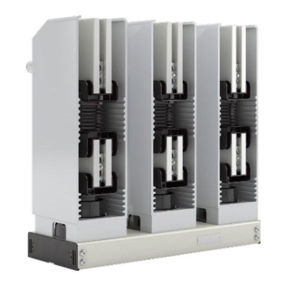
General Figure 1 In comparison to conventional circuit breakers, the Tavrida Electric vacuum circuit breakers comprise of two components: · The ISM (Figure 1) · The CM for controlling the ISM and monitoring both modules (Figure 2) Both modules must only be operated together and are meant for indoor installations only. -
Page 10: Des Ign And Method Of Operation: Ism And Cm
Compact design Tavrida Electric develops and produces all vital parts of the circuit breakers themselves. The result of intensive inhouse fundamental and material research are extremely compact vacuum interrupter and magnetic actuators. Optimal selection of all components makes these the most compact and light weight vacuum circuit breaker in the world. - Page 11 Closing In the open position the contacts are kept open by the force of the opening springs. To close the contacts the coils of the magnetic actuators are excited by a current impulse of the close capacitors of the CM. As a result the contacts close.
- Page 12 THIS PAGE INTENTIONALLY LEFT BLANK...
-
Page 13: Receiving, Handling And Storage
Receiving, Handling and Storage... -
Page 14: Packing
Customer reference Article: Article description Serial Number: 35522 TAVRIDA ELECTRIC AG, Wetterkreuz 3, 91058 Erlangen, Germany, Phone: 0049-9131-972079-0 Figure 8 Figure 9 ISM carton package Label 2 Logistics data A label with the following information is fixed on each CM carton package (Figure 10). -
Page 15: Trans Port
Trans port ISM and CM shall be transported in the original packing only. The packed goods shall be handled in accordance with the handling symbols. Loading procedures for ISM packing units shall be carried out only with fork lifts or cranes. If possible the ISM packing unit shall be placed on a palette. -
Page 16: Rating Plates, Warranty Seals
Scope of delivery for the CM: Figure 12 Screwdriver Routine test certificate The devices should be checked visually for: · Mechanical damage, scratches, discolouration, corrosion · Damage to the seals (Figure 17, Figure 18) Any transport damage must be reported immediately to the carrier in writing. Cases of damage must be photographically documented. - Page 17 Conforms to UL STD 508 Certi ed to CAN/CSA-22.2 No. 142-M1987 4000068 Tavrida Electric North America 1105 Cliveden Ave, Delta, BC, Canada 1-866-551-8362 Made in Russia Figure 14 Figure 15 The CM_16 has an additional label for factory programmable settings (Figure 16); see page 32 for detailed information on the settings functions.
-
Page 18: Storage
Arrangement of the labels (Figures 16, 17): 1. Rating plate 2. Serial number 3. Seal 1. Seal 2. Serial Number, date of manufacturing Figure 18 3. Product code Labelling of the CM_16 Figure 17 Labelling ISM The manufacturer accepts no warranty for a device if the seal is broken or has been removed. Storage Should immediate installation not be possible, the ISM and CM shall be stored in the original packing under the following conditions:... -
Page 19: Ins Tallation
Ins tallation... -
Page 20: General, Preparation
Primary part General, Preparation The following regulations must be adhered to during installation, commissioning and operation: · IEC 60694/DIN VDE 0101, General specification for high-voltage switchgear and control gear standards. · VDE 0105, Operation of electrical installations. · DIN VDE 0141, Ground systems for electrical power installations with nominal voltages above 1 kV. ·... - Page 21 Fixing points Nine internal threads for obligatory ISM fixing, which are formed in the module support insulator (M12, maximal torque 40 ± 2 Nm) Eight internal threads on the side of frame for obligatory ISM fixing (M8, maximal torque is 10 ± 1 Nm) Figure 20 Primary terminals connection Bus bars and cables shall be connected with the primary terminals of ISM mechanically in a stress-free manner.
-
Page 22: Minimum Clearances Due To Rated Ins Ulation Voltage
Additional support insulators To avoid unacceptable high electrodynamic impact on the ISM, the bus bar connections shall rest on additional supporting insulators (Figure 25). Additional support insulators are necessary, if the length of unsupported busbars is more than specified in the table below. Short-circuit current, kA Module 20 kA... -
Page 23: Minimum Clearances Due To Electromagnetic Influences
Minimum Clearances due to Electromagnetic Influences The following clearances must be adhered to (Figure 25): Short-circuit current, kA ISM-Type 31.5 , mm ISM15_Shell_2 Coordination of Minimum Clearances In case the minimum clearance L due to 25/31 kA short circuit current exceeds the minimum clearance L due to the rated insulation level, the higher clearance between ISM-frame and adjacent busbars is to be selected. -
Page 24: Interlocking
Interlocking Interlocking mechanism Interlocking mechanism of the module is based on operation of an interlocking shaft that can be rotated clockwise or counter-clockwise. When the interlocking shaft is rotated clockwise the module becomes acceptable for “close” and “open” operations. Hereinafter this position of the module is called “unlatched”. When the shaft is rotated in reverse direction, i.e. - Page 25 Mechanical Interlocking Mechanical interlocking depends on interlocking shaft rotation (refer to figures 28 to 32). The mechanical interface for the connection of mechanical interlocking is placed at the ISM frame between the terminal blocks XT1, XT2 (refer to figure 35). There is a slot on the visible face of the interlocking shaft. If the slot is directed vertically the module is in “unlatched”...
-
Page 26: Main Contacts Position Indicator
Load capacity of interlocking shaft Interdependence between torque on the interlocking shaft and turning angle of the shaft when switching modu- le has been previously switched off is presented on figure 36. Peak values of the torque are from 0.56 to 0.84 Nm. When shaft is rotated counter-clockwise the interlocking unit is moved from “Unlatched”... - Page 27 Frame Spring Indicator plate Window Adjusting mechanism Figure 37 Position indicator with flexible link Indication of ISM-position by indicator plate depending on position of synchronizing shaft trunnion Figure 38 Figure 39 Position of trunnion at opened ISM Position of trunnion at closed ISM...
- Page 28 Position indicator mounting Position indicator mounting is shown below step by step. (Figures 40, 41, 42, 43, 44, 45). ISM main contacts shall be in closed position. Note: Bending radius of the position indicator flexible link shall be not less than 40 mm to prevent decreasing performance or malfunction.
-
Page 29: Secondary Connections Of The Ism
Secondary Part Secondary Connections of the ISM All ISM have the same terminals (Figure 46). Connected to the terminal blocks XT1 and XT2 are 13 auxiliary switches (6 “NO”- and 7 “NC”-contacts) and the magnetic actuator coils. Cables for terminal blocks XT1 and XT2 can be installed at right, left or bottom side as shown in figure 46. -
Page 30: Cm Connections
CM connections The connections for basic and extended functions of all available CM can be seen from the following terminal arrangements (Figures 47, 48, and 49). Figure 47 CM_1501_01 Terminal arrangement Terminal No. Connection Terminal No. Connection Terminal No. Connection Auxiliary power Ready (NO) Auxiliary switch ISM (AS1) - Page 31 Figure 48 CM_16_1(60), CM_16_1(220) Terminal arrangement Figure 49 CM_16_2(220) Terminal arrangement Terminal No. Connection Terminal No. Connection Terminal No. Connection Auxiliary power supply Output actuator coil CT input 1 input 1 (SC1) Auxiliary power supply Output actuator coil CT input 1 input 2 (SC2) Digital output 1 (NO)
-
Page 32: Cm_16 Series Factory Programmable Options
CM_16 Series Factory Programmable Options The CM_16 series is a flexible control module option with an array of factory programmable settings for optimizing control of the ISM breakers. When ordering a CM_16, the model code along with the pre-programmed settings code should be submitted to Tavrida. - Page 33 Pre-Programmed Settings Code Designations Table Parameter Settings Option Code Breaker Type ISM15_Shell_2 Undervoltage UV On UV Off UV Delay Undervoltage delay (0 - 60 s) 0 - 60 UV Reclosing Reclosing trips to lockout UV Reclosing Delay Reclosing Delay (15 - 60 s) 15 - 60 Digital Output 1 Disabled...
-
Page 34: Ins Tallation Of The Cm
Ins tallation of the CM The installation of the CM is carried out according to the panel design either on the draw out unit or in the low voltage compartment of the switchboard. It must be separated from the high voltage compartment. The CM shall be installed in an grounded mild steel box with a thickness of not less than 1 mm. -
Page 35: Ins Tallation Of Secondary Cables Between Ism And Cm
Ins tallation of Secondary Cables between ISM and CM The installation of secondary cables between ISM and CM shall be performed regarding the subsequent connecting diagram and indications (figure 53). These instructions are required to achieve best possible protection against electromagnetic influence. - Page 36 THIS PAGE INTENTIONALLY LEFT BLANK...
-
Page 37: Switching And Control Functions
Switching and Control Functions... -
Page 38: Charging Of The Capacitors
Bas ic functions for all control modules Charging of the Capacitors Closing and trip capacitors of the CM are charged when CM is applied to the auxiliary power supply. The charged closing capacitors correspond with the charged springs of a conventional circuit breaker. After the failure of auxiliary power supply any pending trip or any trip command arriving to the CM up to 30s after failure of auxiliary power supply will be executed. -
Page 39: Ism Forced Trip By An Undervoltage Relay (Optional - Cm_1501 Series)
ISM Forced Trip by an Undervoltage Relay (Optional - CM_1501 Series) In cases where the ISM is required to trip when the auxiliary power supply voltage drops below the minimum value an additional undervoltage relay is required (not part of the scope of supply). The trip contact of the undervoltage relay shall be integrated into the dry contact trip command circuit of the CM. -
Page 40: Antipumping Duty
Closed Antipumping Duty Close command Close contact Open Closed For close and trip inputs the following rule Open Trip contact is applicable: During close operation, if a Trip command trip instruction is received before the close Output to instruction becomes passive then the clo- magnetic actuator se instruction will be blocked. -
Page 41: Commiss Ioning, Maintenance
Commiss ioning, Maintenance... -
Page 42: General
When designing and mounting a panel for the first time an acceptance of the equipment must be carried out together with Tavrida Electric in order to ensure the installation conditions. The ISM must always be tested and operated together with the CM. Individual testing is not possible and may lead to the destruction of the ISM. -
Page 43: Maintenance
Operating test Disconnect the breaker from the high voltage source before functional testing. · Turn on the CM auxiliary power supply and check the following operating indications: - The POWER LED must light up immediately. - The READY LED must blink during charging of capacitors and light up continuously within 15 s after switching on. - Page 44 THIS PAGE INTENTIONALLY LEFT BLANK...
-
Page 45: Signalling
Signalling... -
Page 46: Led Indicators And Dry Contacts
LED Indicators and Dry Contacts Functionality Results LED indicators Dry contacts CM_1501_01 Ready Malfunction Ready Malfunction Switch on auxiliary power supply Power supply on BLINKING CM is ready to carryout close Operational command readiness Malfunction CM or ISM Malfunction See wiring diagram on page 63 for details on CM_1501_01 external signalling contacts NO/NC positions. CM_16 maintains the same LED indicator patterns as the CM_1501_01. -
Page 47: Malfunction Indication Table
Malfunction Indication Table The self-monitoring system inside the CM detects eventual malfunctions and report them via the MALFUNCTION LED with various blink signals. The meaning of the blink codes and the variations per type of malfunction are shown in the following table. Recommendation Error Malfunction... - Page 48 · Usually failures need to be fixed to stop malfunction indication. During several malfunction variants of 2- or 5- blink failures, the malfunction indication will disappear with a trip CM command. · In case of internal CM failures please contact your nearest Tavrida Electric partner.
-
Page 49: Special Applications: Fast Switching
Special Applications: Fast Switching... -
Page 50: Fast Transfer Switching
Fast Transfer Switching Sensitive loads in industrial processes are often configured with a secondary primary feed from the utility for backup and reserve power. For sectors such as oil & gas, slow transfer times from traditional switching solutions result in motor stoppages and lost production time while processes are brought back on-line. The high closing and opening speeds of the ISM15_Shell_2 series allow for a packaged solution. -
Page 51: Arc Flash Mitigation
Arc Flash Mitigation A high concern for the electrical industry are incidents of arc flash, whereby a fault is initiated that causes damage to the equipment or serious injury to operators. These faults can be caused by many factors such as poor maintenance, equipment failure, or operator error. - Page 52 VCB15_Shell2_FTS (150...210...275) Type VCB15_Shell2_FAS (150...210...275) Rated data Rated voltage (U r ) 15 kV to 2000 A (210, 275mm PCD) Rated current (I r ) to 1200 A (150 mm PCD) Rated power frequency withstand voltage (U d ) 36 kV Rated lightning impulse withstand voltage (peak) (U p ) to 25 kA @ 15 kV Rated short-circuit breaking current (I sc )
-
Page 53: Product Line
Product Line... -
Page 54: Indoor Switching Modules (Ism)
Indoor switching modules (ISM) Type Rated Rated Short Circuit Rated Pole Center Voltage Continuous Distance Current ISM15_Shell_2(150) 15 kV 31.5 kA (5 kV) 1200 A 150 mm 29 kA (15 kV) ISM15_Shell_2(210) 15 kV 31.5 kA (5 kV) 2000 A 210 mm 29 kA (15 kV) ISM15_Shell_2(275) - Page 55 Dimens ions and Weights...
-
Page 56: Dimens Ions And Weights Of The Ism
FIRST ANGLE PROJECTION THIS DRAWING AND ALL INFORMATION SIZE DWG #: CONTAINED THEREIN IS THE PROPERTY OF FV-ALL_ISM15_Shell_2(150)AD TAVRIDA ELECTRIC AND MAY NOT BE COPIED OR USED IN ANY WAY WITHOUT THE EXPRESS WRITTEN CONSENT OF TAVRIDA ELECTRIC SCALE 1:2.5 SHEET... - Page 57 FIRST ANGLE PROJECTION THIS DRAWING AND ALL INFORMATION SIZE DWG #: CONTAINED THEREIN IS THE PROPERTY OF FV-ALL_ISM15_Shell_2(210)AD TAVRIDA ELECTRIC AND MAY NOT BE COPIED OR USED IN ANY WAY WITHOUT THE EXPRESS WRITTEN CONSENT OF TAVRIDA ELECTRIC SCALE 1:2.5 SHEET...
- Page 58 DWG #: CONTAINED THEREIN IS THE PROPERTY OF T.Davidson Delta, BC V3M 6G9 Canada FV-ALL_ISM15_Shel TAVRIDA ELECTRIC AND MAY NOT BE COPIED OR 95 kV BIL and 2000 A of rated current. [10.83 in] [10.83 in] Tel: 604.540.6600 Fax: 604.540.6604...
-
Page 59: Dimens Ions And Weights Of The Cm
Dimens ions and Weights of the CM CM_1501_01 Weight: 1.5 kg CM_1501_01(12) CM_1501_01(4) CM_16_1 Weight: 1.5 kg CM_16_1(60) CM_16_1(220) CM_16_1(60HS) CM_16_1(220HS) CM_16_2 Weight: 1.5 kg CM_16_2(220) CM_16_2(220HS) -
Page 60: Dimens Ions Of The Position Indicator
Dimens ions of the Position Indicator L = 1 m Dimens ions of Mating Part for Interlocking Shaft Dimensions of interlocking shaft... - Page 61 Mating part with interlocking lever Interlocking shaft with mounted interlocking lever...
-
Page 62: Circuit Diagrams
Circuit Diagrams... -
Page 63: Ism15_Shell_2 With Cm_1501_01
ISM15_Shell_2 with CM_1501_01... -
Page 64: Ism15_Shell_2 With Cm_16_1
ISM15_Shell_2 with CM_16_1... - Page 65 THIS PAGE INTENTIONALLY LEFT BLANK...
-
Page 66: Technical Data
Technical Data... -
Page 67: Indoor Switching Modules (Ism)
Indoor Switching Modules (ISM) ISM15_Shell_2 Type (150...180...210...275) Rated data Rated voltage (U r ) 15 kV to 2000 A (210, 275mm PCD) Rated current (I r ) to 2000 A (150 mm PCD) Rated power frequency withstand voltage (U d ) 36 (42) Rated lightning impulse withstand voltage (peak) (U p ) to 29 kA @ 15 kV... -
Page 68: Control Modules
Control Modules CM_16_1(220) Type CM_1501_01 CM_16_1(60) CM_16_2(220) Type of operation O-0.1s-CO-10s- O-0.3s-CO-10s- O-0.3s-CO-10s- Rated operating sequence CO-10s-CO CO-10s-CO CO-10s-CO Maximum CO operating cycles per hour 19 - 72VDC Auxiliary power supply 24/60 85VDC to 85VDC to Auxiliary power supply 100/220 - DC 370VDC 265VCD 85VAC to... - Page 69 CM_1501_01, CM_16_1, CM_16_2 Electromagnetic compatibility Interference immunity to voltage dips short Voltage oscillations of 15% inter-ruptions and voltage swings in accor- for a period of 2 to 3 s, dance with IEC 61000-4-11, Class V (A) periodic for 5 to 10 s Interference immunity to fast electrical transi- 4 kV ents/bursts to IEC 61 000-4-4, Class IV (A)
- Page 70 CM_16_2 Input for CT power supply Operating current range 2-300 A Power consumption per phase during charging trip capacitors - at 2 A 5 VA - at 5 A 12 VA - at 10 A 25 VA - at 30 A 120 VA - at 300 A 8 kVA...
- Page 71 THIS PAGE INTENTIONALLY LEFT BLANK...
-
Page 72: Regulations And Ambient Conditions
Regulations and Ambient Conditions... -
Page 73: Regulations
3500 4000 Please coordinate the necessarily actions Installation altitude H(m) with Tavrida Electric AG. Figure 59 Correction factor (Ka) for installation altitude (H) m = 1 correction curve for the rated power frequency withstand voltage and rated lightning impulse voltage. -
Page 74: Legal Information
Legal Information... -
Page 75: Warranty
All products are shipped exclusively with original packing to ensure safe transport and avoid transport damage (see Packing, Goods Received). Tavrida Electric will not accept any claims for damages caused by improper transport, storage as well as unpacking. Obvious transport damage must be reported in writing to the supplier as soon as it is discovered. -
Page 76: Environmental Friendliness
© Copyright 2008; Tavrida Electric reserves the right to make changes to the design and data of their products. Tavrida Electric accepts no responsibility or liability for losses or damage caused by improper actions based on this publication. - Page 77 THIS PAGE INTENTIONALLY LEFT BLANK...
- Page 78 TAVRIDA ELECTRIC NA Service Department 1105 Cliveden Avenue Delta, BC, Canada V3M 6G9 E-Mail: service@tavrida-na.com Web: www.tavrida-na.com NON-CONFORMITY REPORT From: TAVRIDA ELECTRIC NA Service Department Address: Address: 1105 Cliveden Avenue Delta, BC Name: Phone: Phone: 604-540-6600 Fax: Fax: 604-540-6604 E-Mail: E-Mail: service@tavrida-na.com...
- Page 79 Date:...
- Page 80 Date:...
- Page 81 Date:...
- Page 82 THIS PAGE INTENTIONALLY LEFT BLANK...
- Page 83 This document is copyright and is intended for users and distributors of Tavrida Electric product. It contains information that is the intellectual property of Tavrida Electric and the document, or any part thereof, should not be copied or reproduced in any form without written permission from Tavrida Electric.
Need help?
Do you have a question about the ISM Shell_2 Series and is the answer not in the manual?
Questions and answers