Friedrich VERT-I-PAK A-Series Installation & Operation Manual
Single package vertical air conditioning system small chassis
Hide thumbs
Also See for VERT-I-PAK A-Series:
- Installation & operation manual (20 pages) ,
- Installation and operation manual (72 pages) ,
- Parts manual (8 pages)
Table of Contents
Advertisement
VERT-I-PAK
Single Package Vertical Air Conditioning System
Small Chassis
8
7
F
E
D
C
B
A
8
7
NOTE: This manual only applies to VEA 9000 - 18000 and VHA 9000-12000 BTU/hr models.
For all other A-series models please refer to manual 95991002_05
C
US
A-Series
®
6
5
6
5
4
3
4
3
VPAK SMALL IOM / 95991001_05
2
1
F
E
D
C
B
DRAWN
eberenguer
4/23/2018
CHECKED
A
TITLE
QA
MFG
APPROVED
SIZE
DWG NO
REV
F
SCALE
1
1
SHEET
OF
2
1
Advertisement
Table of Contents

Related Manuals for Friedrich VERT-I-PAK A-Series


Summary of Contents for Friedrich VERT-I-PAK A-Series
- Page 1 VERT-I-PAK A-Series ® Single Package Vertical Air Conditioning System Small Chassis DRAWN eberenguer 4/23/2018 CHECKED TITLE APPROVED SIZE DWG NO SCALE SHEET NOTE: This manual only applies to VEA 9000 - 18000 and VHA 9000-12000 BTU/hr models. For all other A-series models please refer to manual 95991002_05 VPAK SMALL IOM / 95991001_05...
-
Page 2: Table Of Contents
Table of Contents Warnings __________________________________________________________________________________ 3 General Specifications ______________________________________________________________________________ 4 Chassis Dimensions__________________________________________________________________________5 Electrical Data _____________________________________________________________________________ 6 Air Flow Data ______________________________________________________________________________ 8 Installation Minimum Clearances ________________________________________________________________________ 9 Installation Overview & Dimensions ___________________________________________________________ 10 Closet View _______________________________________________________________________________ 11 Rough Opening Dimensions __________________________________________________________________ 12 Wall Plenum Installation ____________________________________________________________________ 13 Louver Installation _________________________________________________________________________ 17 Chassis Installation ________________________________________________________________________ 19... -
Page 3: Warnings
Congratulations! The Friedrich VPAK has been carefully engineered and manufactured to provide many years of dependable, efficient operation while maintaining a comfortable temperature and humidity level. Many extra features have been built into the unit to ensure quiet operation, optimal circulation of cool, dry air, and the most economic operation. -
Page 4: Specifications
General Specifications Series Electric Heat Size VEA = Cooling + Electric Heat 25 = 2.5 kW Engineering VHA = Heat Pump + 34 = 3.4 kW Code Electric Heat 50 = 5.0 kW RT = Standard Nominal Capacity (Btu /Hr.) Remote Operation 09 = 9000... -
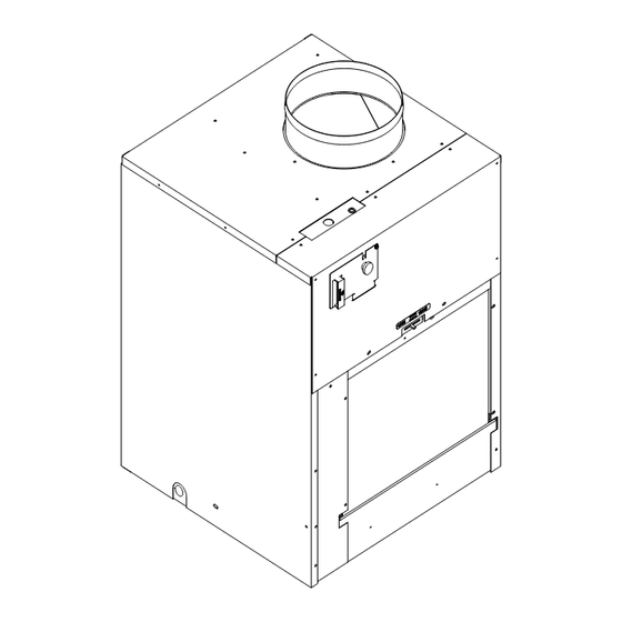
Page 5: Chassis Dimensions
Chassis Dimensions ELECTRICAL ENTRY Front Side Rear 23 1/8” 23 1/8” 10” SUPPLY DUCT DIAMETER 2 15/16” 10 1/8” CONDENSER INLET AIR 29 1/2” 29 1/2” 31” RETURN CONDENSER 19 1/2” EXHAUST 1 1/2”... -
Page 6: Electrical Data
Electrical Data and Specifications MODEL VEA09K VEA12K VEA18K Heater Watts 2500/2050 3400/2780 5000/4090 2500/2050 3400/2780 5000/4090 2500/2050 3400/2780 5000/4090 230/208 230/208 230/208 Voltage 12.0/11.1 Elec. Heating Current (Amps) 16.0/14.6 22.9/20.9 12.0/11.1 16.0/14.6 22.9/20.9 12.0/11.1 16.0/14.6 22.9/20.9 19.9 28.6 19.9 28.6 19.9 28.6 Minimum Circuit Ampacity... - Page 7 Electrical Data and Specifications Electrical Rating Table Electrical Requirements NOTE: Use copper conductors ONLY. Wire sizes are per NEC. Use ONLY wire size recommended for Wire Size single outlet branch circuit. Fuse/Circuit Use ONLY type and size fuse or HACR cir- Recommended Branch Circuit Sizes* Breaker cuit breaker indicated on unit’s rating guide.
-
Page 8: Air Flow Data
Supply Air Flow Data Indoor CFM & External Static Pressure Model VHA09/VEA12/ VEA09 VEA18 VHA12 Fan Speed High High High ESP (“) .10” .15” .20” .25” .30” Indoor air flow may be determined by measuring the external static pressure (ESP) of the duct system using an inclined manometer or magnahelic gauge and consulting the above chart to derive actual air flow. -
Page 9: Minimum Clearances
UNIT of 72” must be kept. FENCE MAJOR OBSTRUCTIONS The the example pictured above is for reference only and does not represent all possible installations. Please contact Friedrich Air Conditioning for information regarding effects of other installation arrangements. -
Page 10: Installation Overview & Dimensions
Installation Overview and Dimensional Data VPAL2 Exterior Wall Plenum Exterior Rough Opening Interior Wall Plenum Chassis 11” Chassis Top View Dimensions Front Chassis (W x D x H) 23 1/8” x 23 1/8” x 32 1/4” 7” Exterior Rough Opening (W x H) 24 5/8”... -
Page 11: Closet View
Closet View Example Closet Optional 25” x 20” access panel filter (field supplied) Rigid Ductwork Exterior Wall VPRG4/R Access Panel and Return Air Grille Flexible Ductwork VPAWPX-XX Electrical Wall Plenum Connection Thermostat Wiring 3/4“ FPT Drain Connection (3) Optional Platform Minimum 3”... -
Page 12: Rough Opening Dimensions
Wall Opening Dimensions Exterior Wall Plenum Cut-Out Dimensions (W x H): 24 5/8” x 30 7/8” 3/4” NOTE: The distance between the rough opening and the finished floor/platform must be 3/4”. If the in- stallation will utilize an auxiliary drain pan it may not exceed 3/4”... -
Page 13: Wall Plenum Installation
Wall Plenum Installation Parts included in Plenum kit: Outside Plenum Half (Part A) Inside Plenum Half (Part B) Field Supplied Parts: Sealant, attachment screws, and flashing Flashing are field supplied. Silicone sealant is recommended. Sealant VPAWP-8 adjust for walls up to 4”- 8” thick. VPAWP-14 adjust for walls up to 8”... - Page 14 Wall Plenum Installation Step 1 - Outside Wall Plenum Half Note: The wall plenum is not designed to carry any structural load. A load bearing header must be built above the rough opening. 1. Prepare the rough opening. The rough opening should be lined with metal or wood. The plenum will warp if sealed against concrete or brick.
- Page 15 Wall Plenum Installation Step 2 - Inside Wall Plenum Half Caulk all 8 Flange Corners and Unused Holes Detail A 1. Apply sealant to all 4 flange corners and unused holes. See Detail A. 2. Flash the inside of the rough opening to ensure the proper fit and level. 3.
- Page 16 Wall Plenum Installation Step 3 - Inside Wall Plenum (cont.) Detail B NOTE: Do not place any screws, fasteners, or penetrating holes through the top or bottom of the plenum assembly. 1. Drill pilot holes on the interior of the inside plenum half (Part B) as show in Detail B. Pilot holes should be located approximately 4”...
-
Page 17: Louver Installation
Louver Installation Installation of the louver PRIOR to wall plenum installation 1. Hold the louver up to the outside plenum half (Part A) and line up the louver top with the very top edge of the ¾” flange. 2. Line up the wall plenum holes with the threaded holes in the louver and securely tighten fasteners. Installation of the louver AFTER the installation of wall plenum on elevated floors From the interior of the utility closet:... - Page 18 Final Wall Plenum and Architectural Louver Installation Louver NOTE: Ensure that the weather strip is undamaged and provides a continuous seal around the inner perimeter of the plenum. Apply silicone grease or other non-petroleum-based lubricants to the weather strip to enhance the sealing capability of the weather strip and ease installation of the air conditioner chassis.
-
Page 19: Chassis Installation
Chassis Installation 1. Ensure that the wall plenum and louver are installed in accordance with the instructions listed on pages 13-18. 2. Place the chassis into the closet with the outdoor side facing the wall plenum opening. 3. Slide the chassis into the wall plenum until the plenum divider seal is established. NOTE: The Vert-I-Pak chassis must be inserted into the wall plenum so that the plenum divider gasket makes contact with the plastic condenser baffle on the unit. -
Page 20: Primary Drain Installation
Primary Drain Installation Nipple 3/4” PVC/NPT Union 3/4” FTP/SLIP Supplied 3/4” plugs Example of field supplied DWV system Threaded end Slip end NOTE: Failure to follow the following procedures may result in serious property damage. A field supplied secondary con- densate pan or P-trap may be required. -
Page 21: Return Air & Ductwork Installation
Indoor Return Air Grille and Ductwork Installation Option 1 Option 2 VPRG4/R Return Air Grille with Access Panel Field Supplied Return Air Grille A field-supplied (25” x 20”) can be mounted inside A field supplied return air grille divorced from the the hinged access door. -
Page 22: Thermostat Installation
Auxiliary Fan Control All Friedrich Vert-I-Pak units are factory configured to be The Friedrich Vert-I-Pak also has the ability to control a controlled by using a single stage heat/cool remote wall 24VAC relay to activate an auxiliary or transfer fan. The mounted thermostat. -
Page 23: Electrical Wiring Diagram
VEA 230/208 Electrical Wiring Diagram... - Page 24 VHA 230/208 Electrical Wiring Diagram BLACK...
- Page 25 VHA 265 Electrical Wiring Diagram BLACK...
-
Page 26: Final Installation Checklist
Authorized leaves the module through a filter and enters the operator of the equipment. Friedrich Warranty Service Company in the area indoor space in front of the indoor conditioning coil. for future reference if necessary. -
Page 27: Service And Warranty
Service & Warranty Servicing / Chassis Quick Change Outs To Remove the Chassis from the Closet: The chassis is designed for quick disconnect 1. Switch the unit off at the thermostat. and change out. For minor electrical service, the 2. Disconnect the power coming into the unit from control box cover lifts straight up after the screws the main breaker panel or the closet mounted and disconnect pull-out are removed. -
Page 28: Diagnostic Error Codes
Diagnostic Error Codes Unit Control Panel The display has four (4) digits. The left two digits indicate the error code (1-24) and the “On/Off” icons above these digits indicate the current state of the error code. The right two digits show the history count (up to 99) of the associated error. The display contains a maintenance icon (wrench) that will illuminate when the unit requires maintenance. - Page 29 THIS PAGE INTENTIONALLY LEFT BLANK.
Need help?
Do you have a question about the VERT-I-PAK A-Series and is the answer not in the manual?
Questions and answers