
Related Manuals for Schweitzer Engineering Laboratories SEL-311C


Summary of Contents for Schweitzer Engineering Laboratories SEL-311C
- Page 1 SEL-311C PROTECTION AND AUTOMATION SYSTEM INSTRUCTION MANUAL SCHWEITZER ENGINEERING LABORATORIES 2350 NE HOPKINS COURT PULLMAN, WA USA 99163-5603 TEL: (509) 332-1890 FAX: (509) 332-7990...
- Page 2 You may not copy, alter, disassemble, or reverse-engineer the software. You may not provide the software to any third party. All brand or product names appearing in this document are the trademark or registered trademark of their respective holders. Schweitzer Engineering Laboratories, SEL , Connectorized, Job Done, SEL-PROFILE,...
- Page 3 Output and Ground and Phase Distance Speed Curves—Fast Hybrid Output. - Added Distance Element Operating Time Curves at Nominal Frequency section. - Updated Frequency Elements section and the Undervoltage Block for Frequency Elements drawing. Date Code 20011205 Manual Change Information SEL-311C Instruction Manual...
- Page 4 Section 5: - Updated Three-Pole Open Logic (Top) and Switch-Onto-Fault Logic (Bottom) drawing. - Updated POTT Logic drawing. - Updated SEL-311C Relay Connections to Communications Equipment for a Three-Terminal Line DCB Scheme drawing. Section 7: - Updated Input Debounce Timers section.
- Page 5 Appendix D: - Updated A5C0 Relay Definition Block section. - Updated information in ID Message and DNA Message sections. Appendix H: - Updated SEL-311C-Wye DNP Data Map table. Appendix J: - Added Appendix J: Unsolicited Fast SER Protocol. 20010820 Section 1: - Added 220 V control input voltage specification to General Specifications.
- Page 6 - Added Warning statement to change default passwords to private passwords at relay installation. Appendix H: - Updated first row of Table H.3. - Correctly identify binary output point 23 in the Relay Summary Event Data subsection. Manual Change Information Date Code 20011205 SEL-311C Instruction Manual...
- Page 7 20000619 Appendix A - Internal changes to support Flash memory revision and battery-backed clock hardware change. 20000421 Switched JMP23 drawings in Table 2.3 in Section 2: Installation. 991201 New Manual Release. Date Code 20011205 Manual Change Information SEL-311C Instruction Manual...
- Page 9 ® Appendix G: Setting SEL Control Equations OGIC Appendix H: Distributed Network Protocol (DNP) 3.00 Appendix I: M ™ Communications IRRORED Appendix J: Unsolicited Fast SER Protocol SEL-311C RELAY COMMAND SUMMARY Date Code 20011205 Table of Contents SEL-311C Instruction Manual...
-
Page 11: Table Of Contents
Relay Element Settings Ranges and Accuracies ..............1-14 TABLES Table 1.1: SEL-311C Relay Models......................1-1 FIGURES Figure 1.1: SEL-311C Relay Transmission Line Protection with Pilot Protection, M IRRORED , Reclosing, and Synch Check ................1-5 Figure 1.2: SEL-311C Relay Inputs, Outputs, and Communications Ports (Models 0311C00x and 0311C01x) .......................1-6... -
Page 13: Introduction And Specifications
Table 1.1 are only the first part of an actual ordering number—enough to distinguish one model type from another. The “x” field indicates horizontal, vertical, rack, or panel mounting. These numbers should not be used to order an SEL-311C Relay. To order an SEL-311C Relay, refer to the actual ordering information sheets. -
Page 14: Instruction Manual Sections Overview
I/O board (and thus increased rack unit height—see Figure 2.1). A vertical SEL-311C Relay is available in both 0311C00x and 0311C01x models. The vertical relays use the same rear panels as the horizontal models in Figure 2.2, Figure 2.3, and Figure 2.7 through Figure 2.10. - Page 15 Relay Word bit table and definitions (Relay Word bits are used in SEL control OGIC equation settings) · Settings Sheets for general relay, SEL control equation, global, SER, text label, and OGIC serial port settings Date Code 20011205 Introduction and Specifications SEL-311C Instruction Manual...
- Page 16 The Settings Sheets can be photocopied and filled out to set the SEL-311C Relay. Note that these sheets correspond to the serial port SET commands listed in Table 9.1. See Section 14 for a description of Application Settings (APP = 221G, 221G5, 221H,...
-
Page 17: Applications
Appendix I: M ™ Communications IRRORED · Appendix J: SEL-311C Unsolicited SER Protocol SEL-311C Relay Command Summary briefly describes the serial port commands that are described in detail in Section 10: Serial Port Communications and Commands. PPLICATIONS SEL-311C SEL-311C IRRORED... -
Page 18: Figure 1.2: Sel-311C Relay Inputs, Outputs, And Communications Ports (Models 0311C00X And 0311C01X)
SEL-311C Relays, use the alphanumeric terminal labels. See Figure 2.2 and Figure 2.7 through Figure 2.10 for rear-panel drawings. Figure 1.2: SEL-311C Relay Inputs, Outputs, and Communications Ports (Models 0311C00x and 0311C01x) Introduction and Specifications Date Code 20011205 SEL-311C Instruction Manual... -
Page 19: Figure 1.3: Sel-311C Relay Extra I/O Board (Model 0311C01X)
See Output Contacts in Section 2: Installation for more information on the polarity dependence of high-current interrupting output contacts. Figure 1.3: SEL-311C Relay Extra I/O Board (Model 0311C01x) Date Code 20011205 Introduction and Specifications SEL-311C Instruction Manual... -
Page 20: Communications Connections
OMMUNICATIONS ONNECTIONS See Port Connector and Communications Cables in Section 10: Serial Port Communications and Commands for more communications connection information. Figure 1.4: SEL-311C Relay Communications Connections Examples Introduction and Specifications Date Code 20011205 SEL-311C Instruction Manual... -
Page 21: Figure 1.5: Sel-311C Relay Communications Connections Examples (Continued)
SEL-311C Relay SEL-311C Relay SEL-2800 SEL-2800 SEL-2800 SEL-2505 Transformer Alarms SEL-2800 SEL-2800 SEL-2100 IN101 Relay Protection Logic Processor M311C091 Figure 1.5: SEL-311C Relay Communications Connections Examples (Continued) Date Code 20011205 Introduction and Specifications SEL-311C Instruction Manual... -
Page 22: Relay Specifications
ELAY PECIFICATIONS Important: Do not use the following specification information to order an SEL-311C Relay. Refer to the actual ordering information sheets. General Specifications Terminal Connections: Rear Screw-Terminal Tightening Torque Terminal Block Minimum: 8-in-lb (0.9 Nm) Maximum: 12-in-lb (1.4 Nm) ®... - Page 23 L/R = 40 ms 125 V 10 A L/R = 40 ms 250 V 10 A L/R = 20 ms Note: Make per IEEE C37.90–1989; Breaking and Cyclic Capacity per IEC 60255-23–1994. Date Code 20011205 Introduction and Specifications 1-11 SEL-311C Instruction Manual...
- Page 24 -40 ° to +85 ° C (-40 ° to +185 ° F) Operating Temperature Range: Note: LCD contrast impaired for temperatures below -20°C. Relay Weight: 2U Rack unit: 13 lbs. (5.92 kg) 3U Rack unit: 16 lbs (7.24 kg) 1-12 Introduction and Specifications Date Code 20011205 SEL-311C Instruction Manual...
-
Page 25: Processing Specifications
One cycle cosine after low-pass analog filtering. Net filtering (analog plus digital) rejects dc and all harmonics greater than the fundamental. Protection and Control Processing 4 times per power system cycle. Date Code 20011205 Introduction and Specifications 1-13 SEL-311C Instruction Manual... -
Page 26: Relay Element Settings Ranges And Accuracies
± 5% of setting at line angle for 30 ≤ SIR ≤ 60 Accuracy: ± 3% of setting at line angle for SIR < 30 Transient Overreach: < 5% of setting plus steady state accuracy 1-14 Introduction and Specifications Date Code 20011205 SEL-311C Instruction Manual... - Page 27 < 5% of pickup Time Delay: 0.00–16,000.00 cycles, 0.25-cycle steps Timer Accuracy: ±0.25 cycle and ±0.1% of setting Max. Operating Time: See pickup and reset time curves in Figure 3.18 and Figure 3.19 Date Code 20011205 Introduction and Specifications 1-15 SEL-311C Instruction Manual...
- Page 28 Maximum Definite-Time Delay ± 0.25 cycles, ± 1% of setting at 60 Hz Accuracy: Steady-State plus Transient ± 0.01 Hz Overshoot: 20–150 V, ± 5%, ± 0.1 V Supervisory 27: 1-16 Introduction and Specifications Date Code 20011205 SEL-311C Instruction Manual...
-
Page 29: Table Of Contents
EIA-232 Serial Port Voltage Jumpers ................2-25 Clock Battery ........................2-26 TABLES Table 2.1: Communication Cables to Connect the SEL-311C Relay to Other Devices ......2-15 Table 2.2: Output Contact Jumpers and Corresponding Output Contacts ..........2-23 Table 2.3: Move Jumper JMP23 to Select Extra Alarm.................2-24 Table 2.4: Password and Breaker Jumper Operation ................2-25... - Page 30 Figure 2.14: SEL-311C Line Protection Through a Delta-Wye Transformer Using Compensator Distance Elements......................2-18 Figure 2.15: Jumper, Connector, and Major Component Locations on the SEL-311C Relay Main Board ..........................2-20 Figure 2.16: Jumper, Connector, and Major Component Locations on the SEL-311C Relay Extra I/O Board........................2-21...
- Page 31 INSTALLATION ELAY OUNTING Figure 2.1: SEL-311C Relay Dimensions and Panel-Mount Cutout To better use Figure 2.1, refer to Table 1.1 for rack unit height information on the SEL-311C Relay models (2U or 3U). Date Code 20011205 Installation SEL-311C Instruction Manual...
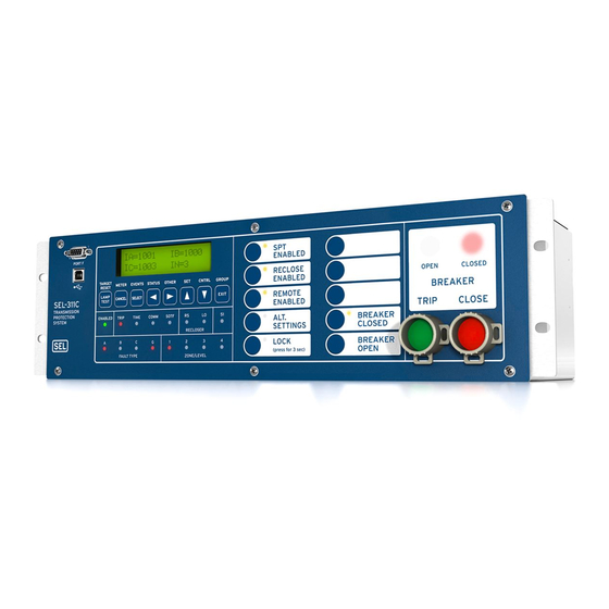
- Page 32 RONT ANEL IAGRAMS Figure 2.2: SEL-311C Relay Front- and Rear-Panel Drawings—Models 0311C00H2 (Rack) and 0311C0032 (Panel) Installation Date Code 20011205 SEL-311C Instruction Manual...
- Page 33 Figure 2.3: SEL-311C Relay Front- and Rear-Panel Drawings—Model 0311C0041 Date Code 20011205 Installation SEL-311C Instruction Manual...
- Page 34 Figure 2.4: SEL-311C Relay Front-Panel Drawings—Models 0311C01H2 (Rack) and 0311C0132 (Panel) Installation Date Code 20011205 SEL-311C Instruction Manual...
- Page 35 Figure 2.5: SEL-311C Relay Front-Panel Drawings—Models 0311C01H1 (Rack) and 0311C0131 (Panel) Date Code 20011205 Installation SEL-311C Instruction Manual...
- Page 36 Figure 2.6: SEL-311C Relay Front-Panel Drawings—Models 0311C0141 and 0311C0142 Installation Date Code 20011205 SEL-311C Instruction Manual...
- Page 37 Figure 2.7: SEL-311C 3U Rear-Panel Terminal Block Drawings (With and Without Additional I/O Board) Date Code 20011205 Installation SEL-311C Instruction Manual...
- Page 38 Figure 2.8: SEL-311C 3U Rear-Panel Terminal Block Drawing (Fast Hybrid High-Current Interrupting Output Contacts) Installation Date Code 20011205 SEL-311C Instruction Manual...
- Page 39 ® Figure 2.9: SEL-311C 2U Rear-Panel Connectorized Drawing Date Code 20011205 Installation SEL-311C Instruction Manual...
- Page 40 Figure 2.10: SEL-311C 3U Rear-Panel Connectorized Drawings (With and Without Additional I/O Board) 2-10 Installation Date Code 20011205 SEL-311C Instruction Manual...
- Page 41 Refer to Section 1: Introduction and Specifications for power supply ratings. The relay power supply rating is listed on the serial number sticker on the relay rear panel. Output Contacts Note: Do not use the following part numbers to order SEL-311C Relays. Contact the SEL factory for ordering information. Model 0311C00x Model 0311C00x can be ordered with standard output contacts only.
- Page 42 Two open switches (one on each side of the contact) defeat the charge circuit. 2-12 Installation Date Code 20011205 SEL-311C Instruction Manual...
- Page 43 (Circuit Load not Shown, Third Terminal Connection Is Optional) Optoisolated Inputs The optoisolated inputs in any of the SEL-311C Relay models (e.g., IN102, IN207) are not polarity dependent. With nominal control voltage applied, each optoisolated input draws approximately 4 mA of current. Refer to General Specifications in Section 1: Introduction and Specifications for optoisolated input ratings.
- Page 44 Serial Port 1 on all the SEL-311C Relay models is an EIA-485 port (4-wire). The Serial Port 1 plug-in connector accepts wire size AWG 24 to 12. Strip the wires 0.31 inches (8 mm) and install with a small slotted-tip screwdriver. The Serial Port 1 connector has extra positions for IRIG-B time-code signal input (see Table 10.2;...
- Page 45 A demodulated IRIG-B time code can be input into Serial Port 2 on any of the SEL-311C Relay models (see Table 10.1) by connecting Serial Port 2 of the SEL-311C Relay to an SEL-2020 with Cable C273A.
- Page 46 Voltage Channel VS is used in voltage and synchronism check elements and voltage metering. Current Channel IP does not need to be connected. Channel IP provides current for current polarized directional elements. Figure 2.12: SEL-311C Relay Provides Distance and Overcurrent Protection, Reclosing, and Synch Check for a Transmission Line 2-16...
- Page 47 In this example, current Channel IP provides current polarization for a directional element used to control ground elements. Figure 2.13: SEL-311C Relay Provides Distance and Overcurrent Protection, and Reclosing for a Transmission Line (Current Polarization Source Connected to...
- Page 48 Use compensator distance elements for line protection through a delta-wye transformer. Voltage VS does not need to be connected. Figure 2.14: SEL-311C Line Protection Through a Delta-Wye Transformer Using Compensator Distance Elements 2-18 Installation Date Code 20011205 SEL-311C Instruction Manual...
- Page 49 Each circuit board corresponds to a row of rear-panel terminal blocks or connectors and is affixed to a drawout tray. Identify which drawout tray needs to be removed. SEL-311C Relay model 0311C00x has only a main board. Model 0311C01x has space for an extra I/O board below the main board.
- Page 50 Figure 2.15: Jumper, Connector, and Major Component Locations on the SEL-311C Relay Main Board 2-20 Installation Date Code 20011205 SEL-311C Instruction Manual...
- Page 51 Figure 2.16: Jumper, Connector, and Major Component Locations on the SEL-311C Relay Extra I/O Board Date Code 20011205 Installation 2-21 SEL-311C Instruction Manual...
- Page 52 Figure 2.17: Interface Board 5 Component Layout 2-22 Installation Date Code 20011205 SEL-311C Instruction Manual...
- Page 53 Figure 2.16 “Extra Alarm” Output Contact Control Jumper All the SEL-311C Relays have dedicated alarm output contacts (labeled ALARM—see Figure 2.2, Figure 2.3, and Figure 2.7). Often more than one alarm output contact is needed for such applications as local or remote annunciation, backup schemes, etc.
- Page 54 Contact Jumpers). Thus, the dedicated ALARM output contact and the “extra alarm” output contact can be configured as the same output contact type if desired (e.g., both can be configured as “b” type output contacts). 2-24 Installation Date Code 20011205 SEL-311C Instruction Manual...
- Page 55 Table 2.5: EIA-232 Serial Port Voltage Jumper Positions for Standard Relay Shipments EIA-232 EIA-232 311C Relay Serial Port 2 Serial Port 3 Reference Model Number (rear panel) (rear panel) Figure 0311C00x JMP2 = OFF JMP1 = OFF Figure 2.15 0311C01x Date Code 20011205 Installation 2-25 SEL-311C Instruction Manual...
- Page 56 (+) of the battery faces up. Reassemble the relay as described in Accessing the Relay Circuit Boards. Set the relay date and time via serial communications port or front panel (see Section 10: Serial Port Communications and Commands or Section 11: Front-Panel Interface). 2-26 Installation Date Code 20011205 SEL-311C Instruction Manual...
- Page 57 Additional Distance Element Supervision ................3-21 Zone 1 Extension ........................3-21 Zone Time Delay Elements....................3-22 Out-of-Step (OOS) Characteristics .....................3-23 Use SEL-321 Relay Application Guides for the SEL-311C Relay........3-24 Instantaneous/Definite-Time Overcurrent Elements ..............3-28 Phase Instantaneous/Definite-Time Overcurrent Elements ..........3-28 Residual Ground Instantaneous/Definite-Time Overcurrent Elements.......3-31 Negative-Sequence Instantaneous/Definite-Time Overcurrent Elements......3-33...
- Page 58 Figure 3.17: Out-of-Step Zone Detection Logic ..................3-26 Figure 3.18: Out-of-Step Logic.......................3-27 Figure 3.19: Levels 1 through 3 Phase Instantaneous/Definite-Time Overcurrent Elements ....3-29 Figure 3.20: SEL-311C Relay Nondirectional Instantaneous Overcurrent Element Pickup Time Curve ..........................3-30 Figure 3.21: SEL-311C Relay Nondirectional Instantaneous Overcurrent Element Reset Time Curve ..........................3-31...
-
Page 59: Distance, Out-Of-Step, Overcurrent, Voltage, Synchronism Check, And Frequency Elements
LEMENTS Mho Phase Distance Elements The SEL-311C Relay has four independent zones of mho phase distance protection. All zones are independently set. Zone 1 and 2 are fixed to operate in the forward direction only. Zones 3 and 4 can be set to operate in either the forward or reverse direction. The phase distance elements use positive-sequence voltage polarization for security and to create an expanded mho characteristic. - Page 60 (-jV - 0.25 • V mem) and the line drop compensated voltage is (V - Z • I Distance, Out-of-Step, Overcurrent, Voltage, Date Code 20011205 Synchronism Check, and Frequency Elements SEL-311C Instruction Manual...
- Page 61 (q) > 0 (Z • I - V) Vmem I • R I • Z source M311B034 Forward Internal Fault Figure 3.1: Positive-Sequence Polarized Mho Element Date Code 20011205 Distance, Out-of-Step, Overcurrent, Voltage, Synchronism Check, and Frequency Elements SEL-311C Instruction Manual...
- Page 62 Fault Near Balance Point Internal Fault Note: V , and V are internal element voltages, not system voltages. M311B035 Figure 3.2: Compensator-Distance Phase-to-Phase Element Operation Distance, Out-of-Step, Overcurrent, Voltage, Date Code 20011205 Synchronism Check, and Frequency Elements SEL-311C Instruction Manual...
- Page 63 The compensator distance element measures impedance through the transformer for all Date Code 20011205 Distance, Out-of-Step, Overcurrent, Voltage, Synchronism Check, and Frequency Elements SEL-311C Instruction Manual...
- Page 64 ±0.01 A and ±3% of setting (1 A nominal) Transient Overreach: < 5% of pickup Max. Operating Time: See pickup and reset time curves in Figure 3.20 and Figure 3.21. Distance, Out-of-Step, Overcurrent, Voltage, Date Code 20011205 Synchronism Check, and Frequency Elements SEL-311C Instruction Manual...
- Page 65 ‚ From Figure 4.15 † From Figure 4.1 ƒ From Figure 3.18 ‡ From Figure 3.15 „ From Figure 3.23 Figure 3.4: Zone 1 AB Phase Distance Logic Date Code 20011205 Distance, Out-of-Step, Overcurrent, Voltage, Synchronism Check, and Frequency Elements SEL-311C Instruction Manual...
- Page 66 From Figure 4.14 „ From Figure 3.23 ‚ From Figure 4.15 … From Figure 4.1 ƒ From Figure 3.18 Figure 3.5: Zone 2 AB Phase Distance Logic Distance, Out-of-Step, Overcurrent, Voltage, Date Code 20011205 Synchronism Check, and Frequency Elements SEL-311C Instruction Manual...
- Page 67 „ From Figure 3.23 ‚ From Figure 4.15 … From Figure 4.1 ƒ From Figure 3.18 Figure 3.6: Zones 3 and 4 AB Phase Distance Logic Date Code 20011205 Distance, Out-of-Step, Overcurrent, Voltage, Synchronism Check, and Frequency Elements SEL-311C Instruction Manual...
-
Page 68: Ground Distance Elements
Ground Distance Elements The SEL-311C Relay has four independent zones of mho and quadrilateral ground distance protection. All zones are independently set. Zones 1 and 2 are forward direction only, and Zones 3 and 4 can be set in either a forward or reverse direction. The mho ground distance elements use positive-sequence voltage polarization for security and to create an expanded mho characteristic. - Page 69 (advanced setting) Settings range for non-homogenous correction angle (hidden and set to -3 when EADVS = N): TANG = -40 to +40 degrees (advanced setting) Date Code 20011205 Distance, Out-of-Step, Overcurrent, Voltage, 3-11 Synchronism Check, and Frequency Elements SEL-311C Instruction Manual...
- Page 70 „ From Figure 4.1 ‚ From Figure 4.2 … From Figure 3.15 ƒ From Figure 5.3 Figure 3.7: Zone 1 Mho Ground Distance Logic 3-12 Distance, Out-of-Step, Overcurrent, Voltage, Date Code 20011205 Synchronism Check, and Frequency Elements SEL-311C Instruction Manual...
- Page 71 Z2MG = Zone 2 Distance Setting M311C044a From Figure 4.12 ƒ From Figure 4.1 ‚ From Figure 5.3 Figure 3.8: Zone 2 Mho Ground Distance Logic Date Code 20011205 Distance, Out-of-Step, Overcurrent, Voltage, 3-13 Synchronism Check, and Frequency Elements SEL-311C Instruction Manual...
- Page 72 = 4 for Zone 4 From Figure 4.12 ƒ From Figure 4.1 ‚ From Figure 5.3 Figure 3.9: Zones 3 and 4 Mho Ground Distance Logic 3-14 Distance, Out-of-Step, Overcurrent, Voltage, Date Code 20011205 Synchronism Check, and Frequency Elements SEL-311C Instruction Manual...
- Page 73 † From Figure 4.2 ƒ From Figure 4.12 ‡ From Figure 3.10 „ From Figure 5.3 Figure 3.10: Zone 1 Quadrilateral Ground Distance Logic Date Code 20011205 Distance, Out-of-Step, Overcurrent, Voltage, 3-15 Synchronism Check, and Frequency Elements SEL-311C Instruction Manual...
- Page 74 „ From Figure 5.3 ‚ From Figure 4.6 … From Figure 4.1 ƒ From Figure 4.12 Figure 3.11: Zone 2 Quadrilateral Ground Distance Logic 3-16 Distance, Out-of-Step, Overcurrent, Voltage, Date Code 20011205 Synchronism Check, and Frequency Elements SEL-311C Instruction Manual...
- Page 75 „ From Figure 5.3 ‚ From Figure 4.6 … From Figure 4.1 ƒ From Figure 4.12 Figure 3.12: Zones 3 and 4 Quadrilateral Ground Distance Logic Date Code 20011205 Distance, Out-of-Step, Overcurrent, Voltage, 3-17 Synchronism Check, and Frequency Elements SEL-311C Instruction Manual...
-
Page 76: Distance Element Operating Time Curves At Nominal Frequency
URVES AT OMINAL REQUENCY Figure 3.13 and Figure 3.14 show operating times for the SEL-311C Relay distance elements. The diagrams show operating times at each test point. Operating times include output contact closure time. For the distance element test, a fault was applied at a location representing a percentage of the Zone 1 relay reach setting. - Page 77 SEL-311C Phase Mho Operating Times Phase-to-Phase Faults 1.75 1.25 SIR = 0.1 SIR = 1.0 SIR = 10.0 SIR = 30.0 0.75 0.25 Fault Location in Percent of Set Reach SEL-311C Mho Ground Operating Times Single-Line-to-Ground Faults 2.25 1.75 SIR = 0.1 1.25...
- Page 78 SEL-311C with Fast Hybrid Output Contacts Phase Mho Operating Times 1.75 1.25 SIR = 0.1 SIR = 1.0 SIR = 10.0 SIR = 30.0 0.75 0.25 100% Fault Location in Percent of Set Reach SEL-311C with Fast Hybrid Output Contacts Ground Mho Operating Times 1.75...
-
Page 79: Additional Distance Element Supervision
Additional Distance Element Supervision The SEL-311C uses Relay Word bit VPOLV for positive-sequence memory supervision of mho and quadrilateral characteristics. VPOLV asserts when the memorized positive-sequence polarizing voltage is greater than 1 Volt. Phase and ground distance elements are supervised with Fault Identification Selection (FIDS) logic. -
Page 80: Zone Time Delay Elements
Figure 3.15: Zone 1 Extension Logic Zone Time Delay Elements The SEL-311C Relay supports two philosophies of zone timing: independent or common timing (see Figure 3.16). For the independent timing mode, the phase and ground distance elements drive separate timers for each zone. For the common mode, the phase and ground distance elements both drive a common timer. -
Page 81: Out-Of-Step (Oos) Characteristics
Normally, the Zone 5 and Zone 6 bottom reactance and left resistance element settings are mirror images of the top reactance and right resistance element settings (e.g., X1B5 = -X1T5). The SEL-311C makes these settings automatically. Enable the advanced user settings to set these elements individually (EADVS = Y). -
Page 82: Use Sel-321 Relay Application Guides For The Sel-311C Relay
EOOS must equal N. Use SEL-321 Relay Application Guides for the SEL-311C Relay The out-of-step logic and settings in the SEL-311C Relay are the same as those in the SEL-321-5 Relay. Refer to Application Guide 97-13: SEL-321-5 Relay Out-of-Step Logic for applying the out-of-step logic in the SEL-311C Relay. - Page 83 Out-of-step block OSB3 Block Zone 3 during an out-of-step condition OSTI Incoming out-of-step trip OSB4 Block Zone 4 during an out-of-step condition Date Code 20011205 Distance, Out-of-Step, Overcurrent, Voltage, 3-25 Synchronism Check, and Frequency Elements SEL-311C Instruction Manual...
- Page 84 Re (Z1) Zone 5 X5ABC (Internal Function) Unblock UBOSBD UBOSB M311C050a From Figure 5.3 ‚ From Figure 4.1 Figure 3.17: Out-of-Step Zone Detection Logic 3-26 Distance, Out-of-Step, Overcurrent, Voltage, Date Code 20011205 Synchronism Check, and Frequency Elements SEL-311C Instruction Manual...
- Page 85 From Figure 3.17 ƒ To Figure 3.5 ‚ To Figure 3.4 „ To Figure 3.6 Figure 3.18: Out-of-Step Logic Date Code 20011205 Distance, Out-of-Step, Overcurrent, Voltage, 3-27 Synchronism Check, and Frequency Elements SEL-311C Instruction Manual...
-
Page 86: Phase Instantaneous/Definite-Time Overcurrent Elements
Ideally, set 50P1P > 50P2P > 50P3P so that overcurrent elements will display in an organized fashion in event reports (see Figure 3.19 and Table 12.3). 3-28 Distance, Out-of-Step, Overcurrent, Voltage, Date Code 20011205 Synchronism Check, and Frequency Elements SEL-311C Instruction Manual... - Page 87 1 (e.g., 67P1TC = 1) for the factory default settings. See SHO Command (Show/View Settings) in Section 10: Serial Port Communications and Commands for a list of the factory default settings. Date Code 20011205 Distance, Out-of-Step, Overcurrent, Voltage, 3-29 Synchronism Check, and Frequency Elements SEL-311C Instruction Manual...
- Page 88 Figure 3.20 and Figure 3.21 show pickup and reset time curves applicable to all nondirectional instantaneous overcurrent elements in the SEL-311C Relay (60 Hz or 50 Hz relays). These times do not include output contact operating time and, thus, are accurate for determining element operation time for use in internal SEL control equations.
-
Page 89: Residual Ground Instantaneous/Definite-Time Overcurrent Elements
Maximum Minimum Applied Current (Multiples of Pickup Setting) Figure 3.21: SEL-311C Relay Nondirectional Instantaneous Overcurrent Element Reset Time Curve Residual Ground Instantaneous/Definite-Time Overcurrent Elements Four levels of residual ground instantaneous/definite-time overcurrent elements are available. The different levels are enabled with the E50G enable setting, as shown in Figure 3.22. - Page 90 DIR 4 = F (Setting) 32GR M311C003a From Figure 4.12 Figure 3.22: Levels 1 Through 4 Residual Ground Instantaneous/Definite-Time Overcurrent Elements With Directional and Torque Control 3-32 Distance, Out-of-Step, Overcurrent, Voltage, Date Code 20011205 Synchronism Check, and Frequency Elements SEL-311C Instruction Manual...
-
Page 91: Negative-Sequence Instantaneous/Definite-Time Overcurrent Elements
OFF, 0.05–20.00 A secondary (1 A nominal phase current inputs, IA, IB, IC) Settings range for definite-time settings 67Q1D through 67Q4D: 0.00–16000.00 cycles, in 0.25-cycle steps Date Code 20011205 Distance, Out-of-Step, Overcurrent, Voltage, 3-33 Synchronism Check, and Frequency Elements SEL-311C Instruction Manual... - Page 92 ±0.25 cycles and ±0.1% of setting Timer: Transient Overreach: < 5% of setting Pickup and Reset Time Curves See Figure 3.20 and Figure 3.21. 3-34 Distance, Out-of-Step, Overcurrent, Voltage, Date Code 20011205 Synchronism Check, and Frequency Elements SEL-311C Instruction Manual...
- Page 93 DIR 4 = F (Setting) 32QR M311C004a From Figure 4.14 Figure 3.23: Levels 1 Through 4 Negative-Sequence Instantaneous/Definite-Time Overcurrent Elements With Directional and Torque Control Date Code 20011205 Distance, Out-of-Step, Overcurrent, Voltage, 3-35 Synchronism Check, and Frequency Elements SEL-311C Instruction Manual...
-
Page 94: Time-Overcurrent Elements
(e.g., 51PTC) cannot be set directly to OGIC logical 0. See Section 9: Setting the Relay for additional time-overcurrent element setting information. 3-36 Distance, Out-of-Step, Overcurrent, Voltage, Date Code 20011205 Synchronism Check, and Frequency Elements SEL-311C Instruction Manual... - Page 95 2 and 30 multiples of pickup 51PT Element Logic Outputs The logic outputs in Figure 3.24 are the Relay Word bits shown in Table 3.5. Date Code 20011205 Distance, Out-of-Step, Overcurrent, Voltage, 3-37 Synchronism Check, and Frequency Elements SEL-311C Instruction Manual...
- Page 96 = 0 (logical 0), if I > pickup setting 51PP and the phase time-overcurrent element is timing or is timed out on its curve 3-38 Distance, Out-of-Step, Overcurrent, Voltage, Date Code 20011205 Synchronism Check, and Frequency Elements SEL-311C Instruction Manual...
- Page 97 The Torque Control Switch closes and phase time-overcurrent element 51PT is enabled and nondirectional. 51PTC = M2P The 51P/51PT uses the Zone 2 mho phase distance element to provide forward directional control. Date Code 20011205 Distance, Out-of-Step, Overcurrent, Voltage, 3-39 Synchronism Check, and Frequency Elements SEL-311C Instruction Manual...
-
Page 98: Residual Ground Time-Overcurrent Element
Phase Time-Overcurrent Elements subsection, substituting residual ground current I = 3I ) for maximum phase current I and substituting like settings and Relay Word bits. 3-40 Distance, Out-of-Step, Overcurrent, Voltage, Date Code 20011205 Synchronism Check, and Frequency Elements SEL-311C Instruction Manual... - Page 99 (e.g., 51GTC) cannot be set directly to OGIC logical 0. See Section 9: Setting the Relay for additional time-overcurrent element settings information. Date Code 20011205 Distance, Out-of-Step, Overcurrent, Voltage, 3-41 Synchronism Check, and Frequency Elements SEL-311C Instruction Manual...
-
Page 100: Negative-Sequence Time-Overcurrent Element
Relay Word bits. Figure 3.26: Negative-Sequence Time-Overcurrent Element 51QT IMPORTANT: See Appendix F for information on setting negative-sequence overcurrent elements. 3-42 Distance, Out-of-Step, Overcurrent, Voltage, Date Code 20011205 Synchronism Check, and Frequency Elements SEL-311C Instruction Manual... -
Page 101: Voltage Elements
±1.50 cycles and ±4% of curve time for currents between (and including) 2 and Curve Timing: 30 multiples of pickup OLTAGE LEMENTS Enable SEL-311C voltage elements by making the enable setting: EVOLT = Y Voltage Values Voltage elements operate from the voltage values shown in Table 3.8. Date Code 20011205... -
Page 102: Voltage Element Settings
Voltage Element Settings Table 3.9 lists available voltage elements and the corresponding voltage inputs and settings ranges for the SEL-311C Relay (see Figure 1.2 for voltage input connection). Table 3.9: Voltage Elements Settings and Settings Ranges Voltage Element (Relay Word bits) - Page 103 Figure 3.29 OFF, 0.00–150.00 V secondary 59SP OFF, 0.00–150.00 V secondary Accuracy Pickup: ±1 V and ±5% of setting < 5% of setting Transient Overreach: Date Code 20011205 Distance, Out-of-Step, Overcurrent, Voltage, 3-45 Synchronism Check, and Frequency Elements SEL-311C Instruction Manual...
- Page 104 Figure 3.27: Single-Phase and Three-Phase Voltage Elements 3-46 Distance, Out-of-Step, Overcurrent, Voltage, Date Code 20011205 Synchronism Check, and Frequency Elements SEL-311C Instruction Manual...
- Page 105 Figure 3.28: Phase-to-Phase and Sequence Voltage Elements Date Code 20011205 Distance, Out-of-Step, Overcurrent, Voltage, 3-47 Synchronism Check, and Frequency Elements SEL-311C Instruction Manual...
-
Page 106: Voltage Element Operation
. The logic outputs in Figure 3.27 are the following Relay Word bits: = 1 (logical 1), if V > pickup setting 59P £ pickup setting 59P = 0 (logical 0), if V 3-48 Distance, Out-of-Step, Overcurrent, Voltage, Date Code 20011205 Synchronism Check, and Frequency Elements SEL-311C Instruction Manual... -
Page 107: Synchronism Check Elements
The remainder of this discussion assumes TCLOSD is not set to OFF. With TCLOSD not set to OFF, the synchronism check is performed as described in either the top or bottom of Figure 3.31, depending on the slip frequency. Date Code 20011205 Distance, Out-of-Step, Overcurrent, Voltage, 3-49 Synchronism Check, and Frequency Elements SEL-311C Instruction Manual... -
Page 108: Synchronism Check Elements Settings
Tables 9.3 and 9.4 Accuracy Voltage Pickup: ±1 V and ±5% of setting Voltage Transient Overreach: < 5% of setting Slip Pickup: ±0.003 Hz Angle Pickup: ±4° 3-50 Distance, Out-of-Step, Overcurrent, Voltage, Date Code 20011205 Synchronism Check, and Frequency Elements SEL-311C Instruction Manual... - Page 109 See bottom of Figure 3.31 ‚ To Figure 3.31 Figure 3.30: Synchronism Check Voltage Window and Slip Frequency Elements Date Code 20011205 Distance, Out-of-Step, Overcurrent, Voltage, 3-51 Synchronism Check, and Frequency Elements SEL-311C Instruction Manual...
- Page 110 From Figure 3.30 ‚ See Figure 6.1 Figure 3.31: Synchronism Check Elements 3-52 Distance, Out-of-Step, Overcurrent, Voltage, Date Code 20011205 Synchronism Check, and Frequency Elements SEL-311C Instruction Manual...
-
Page 111: Synchronism Check Elements Voltage Inputs
, or V ), designated by setting SYNCP (e.g., if SYNCP = VB, then V Synchronism check voltage, from SEL-311C Relay rear-panel voltage input VS For example, if V is designated as phase input voltage V (setting SYNCP = VB), then rear-panel voltage input VS is connected to B-phase on the other side of the circuit breaker. - Page 112 The absolute value of the Slip Frequency output is run through a comparator and if the slip frequency is less than the maximum slip frequency setting, 25SF, Relay Word bit SF asserts to logical 1. 3-54 Distance, Out-of-Step, Overcurrent, Voltage, Date Code 20011205 Synchronism Check, and Frequency Elements SEL-311C Instruction Manual...
- Page 113 The Angle Difference Calculator calculates the angle difference between voltages V Angle Difference = ½(ÐV - ÐV )½ Voltages V and V are “Slipping” Refer to bottom of Figure 3.31. Date Code 20011205 Distance, Out-of-Step, Overcurrent, Voltage, 3-55 Synchronism Check, and Frequency Elements SEL-311C Instruction Manual...
- Page 114 DWG: M35177 Figure 3.32: Angle Difference Between V and V Compensated by Breaker Close Time < f and V Shown as Reference in This Example) 3-56 Distance, Out-of-Step, Overcurrent, Voltage, Date Code 20011205 Synchronism Check, and Frequency Elements SEL-311C Instruction Manual...
- Page 115 . In order to initiate circuit breaker closing when V * is in phase with V (Angle Difference = 0 degrees), V * has to slip around another revolution, relative to V Date Code 20011205 Distance, Out-of-Step, Overcurrent, Voltage, 3-57 Synchronism Check, and Frequency Elements SEL-311C Instruction Manual...
- Page 116 (Angle Difference = 0 degrees). Then when the circuit breaker main contacts finally close, V is in phase with V , minimizing system shock. But with time limitations 3-58 Distance, Out-of-Step, Overcurrent, Voltage, Date Code 20011205 Synchronism Check, and Frequency Elements SEL-311C Instruction Manual...
-
Page 117: Synchronism Check Applications For Automatic Reclosing And Manual Closing
A single output contact (e.g., OUT102 = CLOSE) can provide the close function for both automatic reclosing and manual closing (see Figure 6.1 logic output). Date Code 20011205 Distance, Out-of-Step, Overcurrent, Voltage, 3-59 Synchronism Check, and Frequency Elements SEL-311C Instruction Manual... -
Page 118: Frequency Elements
Setting/ Voltages – To Frequency Relay Element Logic Word 27B81 – M311C109a – To Figure 3.34 Figure 3.33: Undervoltage Block for Frequency Elements 3-60 Distance, Out-of-Step, Overcurrent, Voltage, Date Code 20011205 Synchronism Check, and Frequency Elements SEL-311C Instruction Manual... - Page 119 81D6T (Setting NFREQ E81 = 6) 81D6P < NFREQ Under- M311C110a Frequency From Figure 3.33 Figure 3.34: Levels 1 Through 6 Frequency Elements Date Code 20011205 Distance, Out-of-Step, Overcurrent, Voltage, 3-61 Synchronism Check, and Frequency Elements SEL-311C Instruction Manual...
- Page 120 Note that pickup settings 81D1P through 81D6P are compared to setting NFREQ. NFREQ is the nominal frequency setting (a global setting), set to 50 or 60 Hz. 3-62 Distance, Out-of-Step, Overcurrent, Voltage, Date Code 20011205 Synchronism Check, and Frequency Elements SEL-311C Instruction Manual...
-
Page 121: Frequency Element Operation
= logical 1 (instantaneous element) 81D1T = logical 1 (time delayed element) Relay Word bit 81D1T asserts to logical 1 only after time delay 81D1D. Date Code 20011205 Distance, Out-of-Step, Overcurrent, Voltage, 3-63 Synchronism Check, and Frequency Elements SEL-311C Instruction Manual... -
Page 122: Frequency Element Uses
The instantaneous frequency elements (81D1 through 81D6) are used in testing only. The time-delayed frequency elements (81D1T through 81D6T) are used for underfrequency load shedding, frequency restoration, and other schemes. 3-64 Distance, Out-of-Step, Overcurrent, Voltage, Date Code 20011205 Synchronism Check, and Frequency Elements SEL-311C Instruction Manual... - Page 123 Settings Ranges ........................4-6 Load-Encroachment Setting Example...................4-6 Convert Power Factors to Equivalent Load Angles ..............4-7 Use SEL-321 Relay Application Guide for the SEL-311C Relay ........4-9 Directional Control for Ground Distance and Residual Ground Overcurrent Elements....4-9 Directional Element Enables....................4-11 Best Choice Ground Directional™ Logic................4-11 Directional Elements......................4-11...
- Page 124 Overcurrent and Phase Distance Elements..............4-20 Figure 4.14: Negative-Sequence Voltage-Polarized Directional Element for Phase Distance and Negative-Sequence Elements ..................4-22 Figure 4.15: Positive-Sequence Voltage-Polarized Directional Element for Phase Distance Elements ........................4-23 Loss-of-Potential, CCVT Transient Detection, Date Code 20011205 Load-Encroachment, and Directional Element Logic SEL-311C Instruction Manual...
-
Page 125: Loss-Of-Potential, Ccvt Transient Detection, Load-Encroachment, And Directional Element Logic
(V secondary) zero-sequence current (A secondary) The circuit breaker has to be closed (Relay Word bit 3PO = logical 0) for the LOP logic to operate. Date Code 20011205 Loss-of-Potential, CCVT Transient Detection, Load-Encroachment, and Directional Element Logic SEL-311C Instruction Manual... -
Page 126: Setting Elop = Y Or Y1
In Figure 5.6, if setting ELOP = Y1 and LOP asserts, keying and echo keying in the permissive overreaching transfer trip (POTT) logic are blocked. Loss-of-Potential, CCVT Transient Detection, Date Code 20011205 Load-Encroachment, and Directional Element Logic SEL-311C Instruction Manual... -
Page 127: Setting Elop = Y
ETECTION OGIC The SEL-311C detects CCVT transients that may cause Zone 1 distance overreach. If CCVT transient blocking is enabled (setting ECCVT = Y), and the relay detects a high SIR during a Zone 1 fault, the relay delays tripping for up to 1.5 cycles, allowing the CCVT to stabilize. -
Page 128: Load-Encroachment Logic
The distance elements, M1P through M4P, will not operate without directional control. Set !ZLOAD in the phase overcurrent torque control equation to block phase overcurrent operation. Loss-of-Potential, CCVT Transient Detection, Date Code 20011205 Load-Encroachment, and Directional Element Logic SEL-311C Instruction Manual... - Page 129 Forward load (load flowing out) lies within the hatched region labeled ZLOUT. Relay Word bit ZLOUT asserts to logical 1 when the load lies within this hatched region. Date Code 20011205 Loss-of-Potential, CCVT Transient Detection, Load-Encroachment, and Directional Element Logic SEL-311C Instruction Manual...
-
Page 130: Settings Ranges
132.8 kV • (1000 V / kV) = 132800 V primary 132800 V primary • (1 / PT ratio) = 132800 V primary • (1 V secondary / 2000 V primary) = 66.4 V secondary Loss-of-Potential, CCVT Transient Detection, Date Code 20011205 Load-Encroachment, and Directional Element Logic SEL-311C Instruction Manual... -
Page 131: Convert Power Factors To Equivalent Load Angles
Setting NLAR = 180° + cos (0.95) = 180° + 18° = 198° Apply Load-Encroachment Logic to a Phase Time-Overcurrent Again, from Figure 4.3: ZLOAD = ZLOUT + ZLIN Date Code 20011205 Loss-of-Potential, CCVT Transient Detection, Load-Encroachment, and Directional Element Logic SEL-311C Instruction Manual... - Page 132 For a fault condition (ZLOAD = logical 0), phase time-overcurrent element 51PT can operate: 51PTC = !ZLOAD = !(logical 0) = NOT(logical 0) = logical 1 Loss-of-Potential, CCVT Transient Detection, Date Code 20011205 Load-Encroachment, and Directional Element Logic SEL-311C Instruction Manual...
-
Page 133: Use Sel-321 Relay Application Guide For The Sel-311C Relay
Use SEL-321 Relay Application Guide for the SEL-311C Relay The load-encroachment logic and settings in the SEL-311C Relay are the same as those in the SEL-321 Relay. Refer to Application Guide 93-10: SEL-321 Relay Load-Encroachment Function Setting Guidelines for applying the load-encroachment logic in the SEL-311C Relay. - Page 134 Best Choice Ground Directional™ logic control. See discussion on setting ORDER in the following subsection Directional Control Settings. 4-10 Loss-of-Potential, CCVT Transient Detection, Date Code 20011205 Load-Encroachment, and Directional Element Logic SEL-311C Instruction Manual...
-
Page 135: Directional Element Enables
Refer to Figure 4.5 and Figure 4.12. The directional element outputs are routed to the forward (Relay Word bit 32GF) and reverse (Relay Word bit 32GR) logic points. Date Code 20011205 Loss-of-Potential, CCVT Transient Detection, 4-11 Load-Encroachment, and Directional Element Logic SEL-311C Instruction Manual... - Page 136 Refer to Figure 4.1 and accompanying text for more information on loss-of-potential. As shown in Figure 3.4 through Figure 3.12, ILOP also disables all ground distance elements. 4-12 Loss-of-Potential, CCVT Transient Detection, Date Code 20011205 Load-Encroachment, and Directional Element Logic SEL-311C Instruction Manual...
- Page 137 ‚ To Figure 4.9 … To Figure 4.9 ƒ To Figure 4.14 Figure 4.6: Internal Enables (32QE and 32QGE) Logic for Negative-Sequence Voltage- Polarized Directional Elements Date Code 20011205 Loss-of-Potential, CCVT Transient Detection, 4-13 Load-Encroachment, and Directional Element Logic SEL-311C Instruction Manual...
- Page 138 ‚ To Figure 4.11 „ To Figure 4.8 Figure 4.7: Internal Enables (32VE and 32IE) Logic for Zero-Sequence Voltage-Polarized and Channel IP Current-Polarized Directional Elements 4-14 Loss-of-Potential, CCVT Transient Detection, Date Code 20011205 Load-Encroachment, and Directional Element Logic SEL-311C Instruction Manual...
- Page 139 From Figure 4.6 „ Figure 4.10 ‚ From Figure 4.7 … Figure 4.11 ƒ Figure 4.9 Figure 4.8: Best Choice Ground Directional Logic Date Code 20011205 Loss-of-Potential, CCVT Transient Detection, 4-15 Load-Encroachment, and Directional Element Logic SEL-311C Instruction Manual...
- Page 140 ƒ From Figure 4.8 ‚ From Figure 4.1 „ To Figure 4.12 Figure 4.9: Negative-Sequence Voltage-Polarized Directional Element for Ground Distance and Residual Ground Overcurrent Elements 4-16 Loss-of-Potential, CCVT Transient Detection, Date Code 20011205 Load-Encroachment, and Directional Element Logic SEL-311C Instruction Manual...
- Page 141 ƒ From Figure 4.8 ‚ From Figure 4.1 „ To Figure 4.12 Figure 4.10: Zero-Sequence Voltage-Polarized Directional Element for Ground Distance and Residual Ground Overcurrent Elements Date Code 20011205 Loss-of-Potential, CCVT Transient Detection, 4-17 Load-Encroachment, and Directional Element Logic SEL-311C Instruction Manual...
- Page 142 ƒ From Figure 4.8 ‚ From Figure 4.1 „ To Figure 4.12 Figure 4.11: Channel IP Current-Polarized Directional Element for Ground Distance and Residual Ground Overcurrent Elements 4-18 Loss-of-Potential, CCVT Transient Detection, Date Code 20011205 Load-Encroachment, and Directional Element Logic SEL-311C Instruction Manual...
- Page 143 † To Figure 3.7–Figure 3.12 ƒ From Figure 4.9 and Figure 3.22 „ From Figure 4.10 Figure 4.12: Ground Distance and Residual Ground Directional Logic Date Code 20011205 Loss-of-Potential, CCVT Transient Detection, 4-19 Load-Encroachment, and Directional Element Logic SEL-311C Instruction Manual...
-
Page 144: Internal Enables
The Relay Word bit 32QE enables the negative-sequence voltage-polarized directional element. The settings involved with 32QE in Figure 4.6 (e.g., setting a2) are explained in a following subsection Directional Control Settings. 4-20 Loss-of-Potential, CCVT Transient Detection, Date Code 20011205 Load-Encroachment, and Directional Element Logic SEL-311C Instruction Manual... -
Page 145: Directional Elements
Refer to Figure 4.1 and accompanying text for more information on loss-of-potential. As shown in Figure 3.4 through Figure 3.6, ILOP also disables all phase distance elements. Date Code 20011205 Loss-of-Potential, CCVT Transient Detection, 4-21 Load-Encroachment, and Directional Element Logic SEL-311C Instruction Manual... - Page 146 From Figure 4.1 ‚ To Figure 3.4, Figure 3.5, Figure 3.6, and Figure 3.23 Figure 4.14: Negative-Sequence Voltage-Polarized Directional Element for Phase Distance and Negative-Sequence Elements 4-22 Loss-of-Potential, CCVT Transient Detection, Date Code 20011205 Load-Encroachment, and Directional Element Logic SEL-311C Instruction Manual...
-
Page 147: Directional Control Settings
Once these settings are calculated automatically, they can only be modified if the user goes back and changes the directional control enable setting to E32 = Y. Date Code 20011205 Loss-of-Potential, CCVT Transient Detection, 4-23 Load-Encroachment, and Directional Element Logic SEL-311C Instruction Manual... - Page 148 Most communications-assisted trip schemes set with Zone 3/Level 3 element direction reverse (DIR3 = R). ORDER—Ground Directional Element Priority Setting Setting Range: Negative-sequence voltage-polarized directional element Zero-sequence voltage-polarized directional element Channel IP current-polarized directional element 4-24 Loss-of-Potential, CCVT Transient Detection, Date Code 20011205 Load-Encroachment, and Directional Element Logic SEL-311C Instruction Manual...
- Page 149 Z2R must be greater in value than setting Z2F by 0.1 W (5A nominal) or 0.5 W (1A nominal). Date Code 20011205 Loss-of-Potential, CCVT Transient Detection, 4-25 Load-Encroachment, and Directional Element Logic SEL-311C Instruction Manual...
- Page 150 It keeps the elements from operating for negative-sequence current (system unbalance), which circulates due to line asymmetries, CT saturation during three-phase faults, etc. 4-26 Loss-of-Potential, CCVT Transient Detection, Date Code 20011205 Load-Encroachment, and Directional Element Logic SEL-311C Instruction Manual...
- Page 151 × . directional elements to be enabled ( I ). Again, this presumes at least one of the enables 32VE or 32IE is asserted. Date Code 20011205 Loss-of-Potential, CCVT Transient Detection, 4-27 Load-Encroachment, and Directional Element Logic SEL-311C Instruction Manual...
- Page 152 It keeps the elements from operating for zero-sequence current (system unbalance), which circulates due to line asymmetries, CT saturation during three- phase faults, etc. 4-28 Loss-of-Potential, CCVT Transient Detection, Date Code 20011205 Load-Encroachment, and Directional Element Logic SEL-311C Instruction Manual...
- Page 153 Most often, this setting is set directly to logical 1: E32IV = 1 (numeral 1) Date Code 20011205 Loss-of-Potential, CCVT Transient Detection, 4-29 Load-Encroachment, and Directional Element Logic SEL-311C Instruction Manual...
- Page 154 E32IV OGIC should be deasserted to logical 0. In this example, this is accomplished by connecting a circuit breaker auxiliary contact from the identified circuit breaker to the SEL-311C Relay: E32IV = IN106 (52a connected to optoisolated input IN106) Almost any desired control can be set in SEL control equation setting E32IV.
- Page 155 Trip Settings TRSOTF and TR ...................5-11 Trip Setting DTT.........................5-12 Use Existing SEL-321 Relay Application Guides for the SEL-311C Relay......5-12 Permissive Overreaching Transfer Trip (POTT) Logic .............5-13 Use Existing SEL-321 Relay POTT Application Guide for the SEL-311C Relay ....5-13 External Inputs ........................5-13 Timer Settings........................5-14 Logic Outputs........................5-15 Weak-Infeed Logic and Settings ....................5-15...
- Page 156 Figure 5.5: Permissive Input Logic Routing to POTT Logic ...............5-14 Figure 5.6: POTT Logic........................5-17 Figure 5.7: Permissive Input Logic Routing to Trip Logic ..............5-18 Figure 5.8: SEL-311C Relay Connections to Communications Equipment for a Two-Terminal Line POTT Scheme......................5-19 Figure 5.9: SEL-311C Relay Connections to Communications Equipment for a Three-Terminal Line POTT Scheme......................5-19...
-
Page 157: Trip And Target Logic
Minimum Trip Duration Time. This timer establishes the minimum time duration for which the TRIP Relay Word bit asserts. The settable range for this timer is 4–16,000 cycles. See Figure 5.2. Date Code 20011205 Trip and Target Logic SEL-311C Instruction Manual... - Page 158 TRSOTF is set with instantaneous directional and non-directional elements. From Figure 5.7 „ From Figure 5.14 ‚ From Figure 5.6 … From Figure 5.3 ƒ From Figure 5.11 Figure 5.1: Trip Logic Trip and Target Logic Date Code 20011205 SEL-311C Instruction Manual...
-
Page 159: Set Trip
Relay Word bit OC asserts for execution of the OPEN Command. See OPE Command (Open Breaker) in Section 10: Serial Port Communications and Commands for more information on the OPEN Command. More discussion follows later on the factory settings for setting TR. Date Code 20011205 Trip and Target Logic SEL-311C Instruction Manual... -
Page 160: Unlatch Trip
OGIC TR = M1P + Z1G + M2PT + Z2GT + 51GT + 51QT + OC (trip conditions) ULTR = !(50L + 51G) (unlatch trip conditions) Trip and Target Logic Date Code 20011205 SEL-311C Instruction Manual... -
Page 161: Additional Settings Examples
Input IN101 has to be deenergized (52a circuit breaker auxiliary contact has to be open) before the trip logic unlatches and the TRIP Relay Word bit deasserts to logical 0. ULTR = !52A = NOT(52A) Date Code 20011205 Trip and Target Logic SEL-311C Instruction Manual... -
Page 162: Switch-Onto-Fault (Sotf) Trip Logic
TRSOTF (e.g., TRSOTF = 50P2) to trip after the circuit breaker closes. Figure 5.3 and the following discussion describe the three-pole open (3PO) logic and the SOTF logic. Trip and Target Logic Date Code 20011205 SEL-311C Instruction Manual... -
Page 163: Three-Pole Open Logic
If OPO = 52, and the circuit breaker is open (52A = logical 0) and current is below phase pickup 50LP (50L = logical 0), then the three-pole open (3PO) condition is true: 3PO = logical 1 (circuit breaker open) Date Code 20011205 Trip and Target Logic SEL-311C Instruction Manual... -
Page 164: Circuit Breaker Operated Switch-Onto-Fault Logic
(circuit breaker closed) Determining Three-Pole Open Condition Without Circuit Breaker Auxiliary Contact (OPO = 52) If a circuit breaker auxiliary contact is not connected to the SEL-311C Relay and OPO = 52, control equation setting 52A may be set: OGIC... -
Page 165: Close Bus Operated Switch-Onto-Fault Logic
Circuit breaker closure is detected by monitoring the dc close bus. This is accomplished by wiring an optoisolated input on the SEL-311C Relay (e.g., IN105) to the dc close bus. When a manual close or automatic reclosure occurs, optoisolated input IN105 is energized. SEL... -
Page 166: Enable Setting Ecomm
SSISTED OGIC ENERAL VERVIEW The SEL-311C Relay includes communications-assisted tripping schemes that provide unit- protection for transmission lines with the help of communications. No external coordination devices are required. Figure 5.4: Communications-Assisted Tripping Scheme Refer to Figure 5.4 and the top half of Figure 5.1. -
Page 167: Trip Setting Trcomm
TRSOTF OGIC and TR can also be used, in addition to setting TRCOMM. Setting TRSOTF can be set as described in preceding subsection Switch-Onto-Fault (SOTF) Trip Logic. Date Code 20011205 Trip and Target Logic 5-11 SEL-311C Instruction Manual... -
Page 168: Trip Setting Dtt
IN102 = PT PT1 = IN102 (received permissive trip) In the above SEL-311C Relay setting example, Relay Word bit IN102 is set in the PT1 SEL OGIC control equation. Optoisolated input IN102 is wired to a communications equipment receiver output contact. Relay Word bit IN102 can also be used in other SEL... -
Page 169: Permissive Overreaching Transfer Trip (Pott) Logic
The SEL-321 Relay handles trip unlatching with setting TULO. The SEL-311C Relay handles trip unlatching with SEL control equation setting ULTR. OGIC The SEL-321 Relay has single-pole trip logic. The SEL-311C Relay does not have single-pole trip logic. (POTT) L ERMISSIVE... -
Page 170: Timer Settings
PT1—Received Permissive Trip Signal(s) In two-terminal line POTT applications, a permissive trip signal is received from one remote terminal. One optoisolated input on the SEL-311C Relay (e.g., input IN104) is driven by a communications equipment receiver output (see Figure 5.8). Make SEL... -
Page 171: Logic Outputs
Zone 1 elements of the strong terminal do not pick up, and the fault is not cleared rapidly. This is because the weak terminal protective elements do not operate. Note that while the weak-infeed terminal contributes little fault current, the phase voltage(s) are depressed. Date Code 20011205 Trip and Target Logic 5-15 SEL-311C Instruction Manual... -
Page 172: Sel-311C Relay Weak-Infeed Logic
SEL-311C Relay Weak-Infeed Logic Enable the weak-infeed logic by setting EWFC = Y. The SEL-311C Relay provides additional logic (see Figure 5.6) for weak-infeed terminals to permit rapid tripping of both line terminals for internal faults near the weak terminal. The strong terminal is permitted to trip via the permissive signal echoed back from the weak terminal. - Page 173 ‚ From Figure 3.6 ‡ From Figure 5.5 ƒ From Figure 3.9 ˆ From Figure 5.1 „ From Figure 3.22 ‰ Figure 5.1 … From Figure 3.23 Figure 5.6: POTT Logic Date Code 20011205 Trip and Target Logic 5-17 SEL-311C Instruction Manual...
-
Page 174: Variations For Permissive Underreaching Transfer Trip (Putt) Scheme
OUT105 = M1P + Z1G + 67G1 + 67Q1 + EKEY In a three-terminal line scheme, another output contact (e.g., OUT107) is set the same as OUT105 (see Figure 5.9). 5-18 Trip and Target Logic Date Code 20011205 SEL-311C Instruction Manual... -
Page 175: Installation Variations
(TX) on the communication equipment in Figure 5.9. Then output contact OUT107 can be used for another function. Figure 5.8: SEL-311C Relay Connections to Communications Equipment for a Two-Terminal Line POTT Scheme Figure 5.9: SEL-311C Relay Connections to Communications Equipment for a... -
Page 176: Directional Comparison Unblocking (Dcub) Logic
In two-terminal line DCUB applications (setting ECOMM = DCUB1), a permissive trip signal is received from one remote terminal. One optoisolated input on the SEL-311C Relay (e.g., input IN104) is driven by a communications equipment receiver output (see Figure 5.12). Make... -
Page 177: Timer Settings
In two-terminal line DCUB applications (setting ECOMM = DCUB1), a loss-of-guard signal is received from one remote terminal. One optoisolated input on the SEL-311C Relay (e.g., input IN105) is driven by a communications equipment receiver output (see Figure 5.12). Make... - Page 178 UBB, depending on enable setting ECOMM = DCUB1 or DCUB2. Relay Word bit UBB is the unblock block input into the trip logic in Figure 5.1. When UBB asserts to logical 1, tripping is blocked. 5-22 Trip and Target Logic Date Code 20011205 SEL-311C Instruction Manual...
- Page 179 To Figure 5.11 ‚ To Figure 5.7 Figure 5.10: DCUB Logic Date Code 20011205 Trip and Target Logic 5-23 SEL-311C Instruction Manual...
-
Page 180: Installation Variations
Depending on the installation, perhaps one output contact (e.g., OUT105 = KEY) could be connected in parallel to both transmitter inputs (TX) on the communications equipment in Figure 5.13. Then output contact OUT107 can be used for another function. 5-24 Trip and Target Logic Date Code 20011205 SEL-311C Instruction Manual... - Page 181 Figure 5.12: SEL-311C Relay Connections to Communications Equipment for a Two-Terminal Line DCUB Scheme (Setting ECOMM = DCUB1) Figure 5.13: SEL-311C Relay Connections to Communications Equipment for a Three-Terminal Line DCUB Scheme (Setting ECOMM = DCUB2) Date Code 20011205 Trip and Target Logic...
-
Page 182: Directional Comparison Blocking (Dcb) Logic
Extends the received block signal by a settable time. Use Existing SEL-321 Relay DCB Application Guide for the SEL-311C Relay Use the existing SEL-321 Relay DCB application guide (AG93-06) to help set up the SEL-311C Relay in a DCB scheme (see preceding subsection Communications-Assisted Trip Logic—... -
Page 183: Timer Settings
Program an output contact to include nondirectional carrier start, in addition to directional start. For example, SEL control equation setting OUT105 is set: OGIC OUT105 = DSTRT + NSTRT Date Code 20011205 Trip and Target Logic 5-27 SEL-311C Instruction Manual... - Page 184 The received block trip input (e.g., BT = IN104) is routed through a dropout timer (BTXD) in the DCB logic in Figure 5.14. The timer output (BTX) is routed to the trip logic in Figure 5.1. 5-28 Trip and Target Logic Date Code 20011205 SEL-311C Instruction Manual...
- Page 185 From Figure 3.6 … From Figure 3.5 ‚ From Figure 3.9 † From Figure 3.8 ƒ From Figure 3.23 ‡ To Figure 5.1 „ From Figure 3.22 Figure 5.14: DCB Logic Date Code 20011205 Trip and Target Logic 5-29 SEL-311C Instruction Manual...
-
Page 186: Installation Variations
Figure 5.16 also shows communications equipment RX (receive) output contacts from each remote terminal connected to separate inputs IN104 and IN106 on the SEL-311C Relay. The inputs operate as block trip receive inputs for the two remote terminals and are used in the... - Page 187 Figure 5.15: SEL-311C Relay Connections to Communications Equipment for a Two-Terminal Line DCB Scheme Figure 5.16: SEL-311C Relay Connections to Communications Equipment for a Three-Terminal Line DCB Scheme Date Code 20011205 Trip and Target Logic 5-31 SEL-311C Instruction Manual...
-
Page 188: Additional Target Led Information
- - - - P RONT ANEL ARGET Table 5.1: SEL-311C Relay Front-Panel Target LED Definitions Number Label Definition Relay Enabled—see subsection Relay Self-Tests in Section 13: Testing and Troubleshooting TRIP Indication that a trip occurred, by a protection or control element... - Page 189 TR—both settings directly assert the TRIP Relay Word bit. The only difference between settings DTT and TR is that setting DTT causes the COMM target LED to illuminate. Many other variations of the above DTT settings examples are possible. Date Code 20011205 Trip and Target Logic 5-33 SEL-311C Instruction Manual...
-
Page 190: Target Reset/Lamp Test Front-Panel Pushbutton
TRGTR pulses to logical 1 for one processing interval when either the TARGET RESET Pushbutton is pushed or the TAR R (Target Reset) serial port command is executed. 5-34 Trip and Target Logic Date Code 20011205 SEL-311C Instruction Manual... - Page 191 Pushbutton (Relay Word bit TRGTR pulses to logical 1, unlatching SV8 and in turn deasserting DP3). Thus, front-panel rotating default displays can be easily reset along with the front-panel targets by pushing the TARGET RESET Pushbutton. Date Code 20011205 Trip and Target Logic 5-35 SEL-311C Instruction Manual...
- Page 193 Table 6.3: Shot Counter Correspondence to Relay Word Bits and Open Interval Times......6-19 Table 6.4: Reclosing Relay SEL Control Equation Settings Example...........6-19 OGIC Table 6.5: Open Interval Time Settings Example ..................6-25 Date Code 20011205 Close and Reclose Logic SEL-311C Instruction Manual...
- Page 194 Figure 6.2: Reclose Supervision Logic (Following Open Interval Time-Out)........6-6 Figure 6.3: Reclose Supervision Limit Timer Operation (Refer to Bottom of Figure 6.2) ....6-7 Figure 6.4: SEL-311C Relays Installed at Both Ends of a Transmission Line in a High-Speed Reclose Scheme ......................6-10 Figure 6.5: Reclosing Relay States and General Operation..............6-13...
-
Page 195: Close And Reclose Logic
(e.g., manual close initiation via serial port or optoisolated inputs). If automatic reclosing is not needed, but the SEL-311C Relay is to close the circuit breaker for other close conditions (e.g., manual close initiation via serial port or optoisolated inputs), then this subsection is the only subsection that needs to be read in ®... -
Page 196: Close Logic
The reclose initiation condition (79RI) is not making a rising edge (logical 0 to logical 1) transition. · And a close failure condition does not exist (Relay Word bit CF = 0). Close and Reclose Logic Date Code 20011205 SEL-311C Instruction Manual... -
Page 197: Unlatch Close
= TRIP The factory setting for the Close Failure Timer setting is: = 60.00 cycles See the settings sheets at the end of Section 9: Setting the Relay for setting ranges. Date Code 20011205 Close and Reclose Logic SEL-311C Instruction Manual... -
Page 198: Defeat The Close Logic
IN101 (for a 52a) or !IN101 (for a 52b). For example, refer to Rotating Default Display in Section 7: Inputs, Outputs, Timers, and Other Control Logic. If circuit breaker status indication is controlled by display point setting DP2: DP2 = IN101 Close and Reclose Logic Date Code 20011205 SEL-311C Instruction Manual... -
Page 199: Program An Output Contact For Closing
CLOSE Relay Word bit to logical 1. This input into the close logic in Figure 6.1 is an output of the reclose supervision logic in the following Figure 6.2. Date Code 20011205 Close and Reclose Logic SEL-311C Instruction Manual... - Page 200 To Figure 6.1 Figure 6.2: Reclose Supervision Logic (Following Open Interval Time-Out) Close and Reclose Logic Date Code 20011205 SEL-311C Instruction Manual...
- Page 201 Figure 6.3: Reclose Supervision Limit Timer Operation (Refer to Bottom of Figure 6.2) Date Code 20011205 Close and Reclose Logic SEL-311C Instruction Manual...
-
Page 202: Settings And General Operation
If 79CLS asserts to logical 1 at any time during this 79CLSD time window, then the open interval time-out will propagate onto the final close logic in Figure 6.1 to automatically reclose the circuit breaker. Close and Reclose Logic Date Code 20011205 SEL-311C Instruction Manual... - Page 203 79CLSD = OFF, reclose supervision condition 79CLS is not time limited. When an open interval times out, reclose supervision condition 79CLS is checked indefinitely until one of the other above unlatch conditions comes true. Date Code 20011205 Close and Reclose Logic SEL-311C Instruction Manual...
-
Page 204: Settings Example
Additional Settings Example 1 Refer to the top of Figure 6.2 and Figure 6.4. SEL-311C Relays are installed at both ends of a transmission line in a high-speed reclose scheme. After both circuit breakers open for a transmission line fault, the SEL-311C(1) Relay recloses circuit breaker 52/1 first, followed by the SEL-311C(2) Relay reclosing circuit breaker 52/2, after a synchronism check across circuit breaker 52/2. - Page 205 SEL-311C(1) Relay Before allowing circuit breaker 52/1 to be reclosed after an open interval time-out, the SEL-311C(1) Relay verifies that Bus 1 voltage is hot and the transmission line voltage is dead. This requires reclose supervision settings: 79CLSD = 0.00 cycles...
-
Page 206: Additional Settings Example 2
The other two unfaulted phases would be briefly energized until circuit breaker 52/1 is tripped again. If channel VS of the SEL-311C(2) Relay is connected to one of these briefly energized phases, synchronism check element 25A1 could momentarily assert to logical 1. -
Page 207: Reclosing Relay States And General Operation
When in reset or lockout, the corresponding Relay Word bit asserts to logical 1, and the LED illuminates. Automatic reclosing only takes place when the relay is in the Reclose Cycle State. Date Code 20011205 Close and Reclose Logic 6-13 SEL-311C Instruction Manual... -
Page 208: Reclosing Relay States After A Settings Or Setting Group Change
The shot counter is driven to last shot (last shot corresponding to the new settings; see discussion on last shot that follows). · The reset timer is loaded with reset time setting 79RSLD (see discussion on reset timing later in this section). 6-14 Close and Reclose Logic Date Code 20011205 SEL-311C Instruction Manual... -
Page 209: Defeat The Reclosing Relay
52A OGIC and CL. Also see Optoisolated Inputs in Section 7: Inputs, Outputs, Timers, and Other Control Logic for more discussion on SEL control equation setting 52A. OGIC Date Code 20011205 Close and Reclose Logic 6-15 SEL-311C Instruction Manual... -
Page 210: Reclosing Relay Timer Settings
The open interval timers time consecutively; they do not have the same beginning time reference point. In the above example settings, open interval 1 time setting, 79OI1, times first. If the 6-16 Close and Reclose Logic Date Code 20011205 SEL-311C Instruction Manual... - Page 211 Reclose Cycle State or the Lockout State. Circuit breaker status is determined by the control equation setting 52A. (See Close Logic earlier in this section for more OGIC discussion on SEL control equation setting 52A. Also see Optoisolated Inputs in OGIC Date Code 20011205 Close and Reclose Logic 6-17 SEL-311C Instruction Manual...
- Page 212 If the reset timer is actively timing, RSTMN asserts to logical 1. If the reset timer is not timing, RSTMN deasserts to logical 0. See Block Reset Timing Setting (79BRS) later in this subsection. 6-18 Close and Reclose Logic Date Code 20011205 SEL-311C Instruction Manual...
-
Page 213: Reclosing Relay Shot Counter
79STL TRIP Stall Open Interval Timing 79BRS Block Reset Timing 79SEQ Sequence Coordination 79CLS Reclose Supervision These example settings are discussed in detail in the remainder of this subsection. Date Code 20011205 Close and Reclose Logic 6-19 SEL-311C Instruction Manual... -
Page 214: Reclose Initiate And Reclose Initiate Supervision Settings (79Ri And 79Ris, Respectively)
SEL-311C to successfully initiate reclosing and start timing on the first open interval. The SEL-311C is not yet in the reclose cycle state (79CY = logical 0) at the instant of the first trip. - Page 215 79RIS = 0 (numeral 0) reclosing will never take place (the reclosing relay goes directly to the lockout state any time reclosing is initiated). The reclosing relay is effectively inoperative. Date Code 20011205 Close and Reclose Logic 6-21 SEL-311C Instruction Manual...
-
Page 216: Drive-To-Lockout And Drive-To-Last Shot Settings (79Dtl And 79Dls, Respectively)
Additional Settings Example in the preceding setting 79RI [reclose initiation] discussion). Then the drive-to-lockout condition overlaps reclose initiation and the SEL-311C stays in lockout after the breaker trips open. When 79DLS = logical 1, the reclosing relay goes to the last shot, if the shot counter is not at a shot value greater than or equal to the calculated last shot (see Reclosing Relay Shot Counter earlier in this subsection). - Page 217 Overall, settings 79DTL or 79DLS are needed to take the relay to the Lockout State (or to last shot) for immediate circumstances. Date Code 20011205 Close and Reclose Logic 6-23 SEL-311C Instruction Manual...
-
Page 218: Skip Shot And Stall Open Interval Timing Settings (79Skp And 79Stl, Respectively)
50P2 threshold (Relay Word bit 50P2 = logical 1), at the instant of successful reclose initiation, the shot counter is incremented from shot = 0 to shot = 1. Then, 6-24 Close and Reclose Logic Date Code 20011205 SEL-311C Instruction Manual... - Page 219 = logical 0, regardless of Relay Word bit 50P2. Additional Settings Example 2 If the SEL-311C Relay is used on a line serving an independent power producer (cogenerator), the utility should not reclose into a line still energized by an islanded generator. To monitor line voltage and block reclosing, connect a line-side single-phase potential transformer to channel VS on the SEL-311C Relay as shown in Figure 6.7.
-
Page 220: Block Reset Timing Setting (79Brs)
Thus, the 79BRS setting has no effect when the relay is in the Reset or Lockout States. When a circuit breaker is closed from lockout, there could be cold load inrush current that momentarily picks up a time-overcurrent element (e.g., phase time-overcurrent element 51PT pickup [51P] 6-26 Close and Reclose Logic Date Code 20011205 SEL-311C Instruction Manual... -
Page 221: Sequence Coordination Setting (79Seq)
Sequence Coordination Setting (79SEQ) The 79SEQ setting is applicable to distribution applications, for transmission system applications set 79SEQ = 0. See the SEL-351 Instruction Manual for a description of setting 79SEQ. Date Code 20011205 Close and Reclose Logic 6-27 SEL-311C Instruction Manual... - Page 223 Operation of Output Contacts for Different Output Contact Types ........7-33 Rotating Default Display (Only on Models with LCD) .............7-36 Traditional Indicating Panel Lights ..................7-37 Traditional Indicating Panel Lights Replaced with Rotating Default Display....7-37 Date Code 20011205 Inputs, Outputs, Timers, and Other Control Logic SEL-311C Instruction Manual...
- Page 224 Figure 7.13: SCADA Contact Pulses Input IN104 to Enable/Disable Reclosing Relay ......7-13 Figure 7.14: Latch Control Switch Controlled by a Single Input to Enable/Disable Reclosing ....7-14 Figure 7.15: Latch Control Switch Operation Time Line...............7-16 Inputs, Outputs, Timers, and Other Control Logic Date Code 20011205 SEL-311C Instruction Manual...
- Page 225 Figure 7.28: Logic Flow for Example Output Contact Operation—Extra I/O Board (Model 0311C01x)........................7-36 Figure 7.29: Traditional Panel Light Installations ..................7-37 Figure 7.30: Rotating Default Display Replaces Traditional Panel Light Installations ......7-38 Date Code 20011205 Inputs, Outputs, Timers, and Other Control Logic SEL-311C Instruction Manual...
- Page 227 NPUTS Figure 7.1 and Figure 7.2 show the resultant Relay Word bits that follow corresponding optoisolated inputs for the different SEL-311C Relay models. The figures show examples of energized and deenergized optoisolated inputs and corresponding Relay Word bit states. To assert an input, apply rated control voltage to the appropriate terminal pair (see Figure 1.2 and...
- Page 228 Figure 7.1: Example Operation of Optoisolated Inputs IN101 Through IN106 (Models 0311C00x and 0311C01x) Figure 7.2: Example Operation of Optoisolated Inputs IN201 Through IN208—Extra I/O Board (Model 0311C01x) Inputs, Outputs, Timers, and Other Control Logic Date Code 20011205 SEL-311C Instruction Manual...
-
Page 229: Inputs, Outputs, Timers, And Other Control Logic
Relay Word bits IN101 through IN106 are used in SEL control equations. OGIC Settings Example 1 Figure 7.3: Circuit Breaker Auxiliary Contact and Reclose Enable Switch Connected to Optoisolated Inputs IN101 and IN102 Date Code 20011205 Inputs, Outputs, Timers, and Other Control Logic SEL-311C Instruction Manual... - Page 230 OGIC setting 79DTL. The pickup/dropout timer for input IN102 (IN102D) in this example might be set at: IN102D = 1.00 cycle to provide input energization/deenergization debounce. Inputs, Outputs, Timers, and Other Control Logic Date Code 20011205 SEL-311C Instruction Manual...
-
Page 231: Local Control Switches
Note: On SEL-311C Relays without an LCD, the Relay Word bits LB1–LB16 are always = logical 0. (Local bit control is not possible because there are no front-panel buttons or display on the relay.) -
Page 232: Local Control Switch Types
The local bit LBn is maintained in the OFF (LBn = logical 0) position and pulses to the MOMENTARY (LBn = logical 1) position for one processing interval (1/4 cycle). Inputs, Outputs, Timers, and Other Control Logic Date Code 20011205 SEL-311C Instruction Manual... - Page 233 Figure 7.7: Local Control Switch Configured as an ON/OFF/MOMENTARY Switch Table 7.2: Correspondence Between Local Control Switch Types and Required Label Settings Local Switch Type Label NLBn Label CLBn Label SLBn Label PLBn ON/OFF OFF/MOMENTARY ON/OFF/MOMENTARY Date Code 20011205 Inputs, Outputs, Timers, and Other Control Logic SEL-311C Instruction Manual...
-
Page 234: Settings Examples
To keep reclosing from being initiated for this trip, set local bit LB3 to drive the reclosing relay to lockout for a manual trip (see Section 6: Close and Reclose Logic): 79DTL = ... + LB3 Inputs, Outputs, Timers, and Other Control Logic Date Code 20011205 SEL-311C Instruction Manual... -
Page 235: Additional Local Control Switch Application Ideas
(Relay Word bits LB1 through LB16) are retained, much like in the preceding Power Loss explanation. Date Code 20011205 Inputs, Outputs, Timers, and Other Control Logic SEL-311C Instruction Manual... -
Page 236: Remote Control Switches
Any given remote control switch can be put in one of the following three positions: (logical 1) (logical 0) MOMENTARY (logical 1 for one processing interval) 7-10 Inputs, Outputs, Timers, and Other Control Logic Date Code 20011205 SEL-311C Instruction Manual... -
Page 237: Remote Bit Application Ideas
The latch control switch feature of this relay replaces latching relays. Traditional latching relays maintain their output contact state when set. The SEL-311C latch bit retains memory even when control power is lost. If the latch bit is set to a programmable output contact and control power is lost, the state of the latch bit is stored in nonvolatile memory but the output contact will go to its deenergized state. - Page 238 Figure 7.11: Traditional Latching Relay The sixteen (16) latch control switches in the SEL-311C Relay provide latching relay type functions. Figure 7.12: Latch Control Switches Drive Latch Bits LT1 Through LT16 The output of the latch control switch in Figure 7.12 is a Relay Word bit LTn (n = 1 through 16), called a latch bit.
-
Page 239: Latch Control Switch Application Ideas
Relay. Reclosing Relay Enable/Disable Setting Example Use a latch control switch to enable/disable the reclosing relay in the SEL-311C Relay. In this example, a SCADA contact is connected to optoisolated input IN104. Each pulse of the SCADA contact changes the state of the reclosing relay. The SCADA contact is not maintained, just pulsed to enable/disable the reclosing relay. - Page 240 The rising edge operator in front of Relay Word bit IN104 (/IN104) sees a logical 0 to logical 1 transition as a “rising edge,” and /IN104 asserts to logical 1 for one processing interval. 7-14 Inputs, Outputs, Timers, and Other Control Logic Date Code 20011205 SEL-311C Instruction Manual...
- Page 241 Thus each individual assertion of input IN104 (Pulse 1, Pulse 2, Pulse 3, and Pulse 4 in Figure 7.15) changes the state of the latch control switch just once. Date Code 20011205 Inputs, Outputs, Timers, and Other Control Logic 7-15 SEL-311C Instruction Manual...
- Page 242 Word bits RB1 through RB16) are operated through the serial port. See Figure 7.10 and Section 10: Serial Port Communications and Commands for more information on remote bits. These are just a few control logic examples—many variations are possible. 7-16 Inputs, Outputs, Timers, and Other Control Logic Date Code 20011205 SEL-311C Instruction Manual...
-
Page 243: Latch Control Switch States Retained
For example, when setting Group 4 becomes the active setting group, latch bit LT2 should be reset. Make the following SEL control equation settings in setting Group 4: OGIC SV7 = SG4 RST2 = !SV7T + ... [= NOT(SV7T) + ...] Date Code 20011205 Inputs, Outputs, Timers, and Other Control Logic 7-17 SEL-311C Instruction Manual... -
Page 244: Note: Make Latch Control Switch Settings With Care
Another variation to the example application in Figure 7.13 through Figure 7.15 that adds more security is a timer with pickup/dropout times set the same (see Figure 7.17 and Figure 7.18). 7-18 Inputs, Outputs, Timers, and Other Control Logic Date Code 20011205 SEL-311C Instruction Manual... - Page 245 Figure 7.17: Latch Control Switch (with Time Delay Feedback) Controlled by a Single Input to Enable/Disable Reclosing Figure 7.18: Latch Control Switch (with Time Delay Feedback) Operation Time Line Date Code 20011205 Inputs, Outputs, Timers, and Other Control Logic 7-19 SEL-311C Instruction Manual...
-
Page 246: Multiple Setting Groups
SS1 through SS6 have priority over the serial port GROUP OGIC command and the front-panel GROUP pushbutton in selecting the active setting group. 7-20 Inputs, Outputs, Timers, and Other Control Logic Date Code 20011205 SEL-311C Instruction Manual... -
Page 247: Operation Of Sel Ogic ® Control Equation Settings Ss1 Through Ss6
See Section 10: Serial Port Communications and Commands for more information on the serial port GROUP command. See Section 11: Front-Panel Interface for more information on the front-panel GROUP pushbutton. Date Code 20011205 Inputs, Outputs, Timers, and Other Control Logic 7-21 SEL-311C Instruction Manual... -
Page 248: Relay Disabled Momentarily During Active Setting Group Change
OGIC Active Setting Group Switching Example 1 Use a single optoisolated input to switch between two setting groups in the SEL-311C Relay. In this example, optoisolated input IN105 on the relay is connected to a SCADA contact in Figure 7.19. Each pulse of the SCADA contact changes the active setting group from one setting group (e.g., setting Group 1) to another (e.g., setting Group 4). -
Page 249: Ogic
SCADA contact (and subsequent assertion of input IN105). The functions of the control equations in Error! Reference source not found. are explained in the OGIC following example. Date Code 20011205 Inputs, Outputs, Timers, and Other Control Logic 7-23 SEL-311C Instruction Manual... - Page 250 Group 1 after qualifying time setting TGR (perhaps set at a cycle or so to qualify the assertion of setting SS1). Optoisolated input IN105 also has its own built-in debounce timer, IN105D (see Figure 7.1). 7-24 Inputs, Outputs, Timers, and Other Control Logic Date Code 20011205 SEL-311C Instruction Manual...
-
Page 251: Active Setting Group Switching Example 2
Group 5 Group 6 The SEL-311C Relay can be programmed to operate similarly. Use three optoisolated inputs to switch between the six setting groups in the SEL-311C Relay. In this example, optoisolated inputs IN101, IN102, and IN103 on the relay are connected to a rotating selector switch in Figure 7.22. - Page 252 SS6 = IN103 * IN102 * !IN101 = IN103 * IN102 * NOT(IN101) The settings in Error! Reference source not found. are made in each setting Group 1 through 6. 7-26 Inputs, Outputs, Timers, and Other Control Logic Date Code 20011205 SEL-311C Instruction Manual...
- Page 253 With settings SS1 through SS6 all at logical 0, the serial port GROUP command or the front- panel GROUP pushbutton can be used to switch the active setting group from Group 5, in this example, to another desired setting group. Date Code 20011205 Inputs, Outputs, Timers, and Other Control Logic 7-27 SEL-311C Instruction Manual...
-
Page 254: Active Setting Group Retained
If the individual settings change causes a change in one or more SEL control equation OGIC settings SS1 through SS6, the active setting group can be changed, subject to the newly enabled SS1 through SS6 settings. 7-28 Inputs, Outputs, Timers, and Other Control Logic Date Code 20011205 SEL-311C Instruction Manual... -
Page 255: Note: Make Active Setting Group Switching Settings With Care
Timers SV7T through SV16T in Figure 7.25 have a setting range of almost 4.5 minutes: 0.00–16000.00 cycles in 0.25-cycle increments These timer setting ranges apply to both pickup and dropout times (SVnPU and SVnDO, n = 1 through 16). Date Code 20011205 Inputs, Outputs, Timers, and Other Control Logic 7-29 SEL-311C Instruction Manual... -
Page 256: Ogic
Figure 7.24: SEL Control Equation Variables/Timers SV1/SV1T Through SV6/SV6T OGIC Figure 7.25: SEL Control Equation Variables/Timers SV7/SV7T Through OGIC SV16/SV16T 7-30 Inputs, Outputs, Timers, and Other Control Logic Date Code 20011205 SEL-311C Instruction Manual... -
Page 257: Settings Example
SV7 being set equal to OGIC Relay Word bit SV7 (SEL control equation variable SV7): OGIC SV7 = (SV7 + IN101) * (50P1 + 50G1) Date Code 20011205 Inputs, Outputs, Timers, and Other Control Logic 7-31 SEL-311C Instruction Manual... -
Page 258: Additional Settings Example 2
0 (assuming input IN101 is not asserted). Relay Word bit SV7T is also reset to logical 0, and timer settings SV7PU and SV7DO load up again. 7-32 Inputs, Outputs, Timers, and Other Control Logic Date Code 20011205 SEL-311C Instruction Manual... -
Page 259: Output Contacts
OUTm (m = 101 through 107) to logical 1 also asserts the OGIC corresponding Relay Word bit OUTm (m = 101 through 107) to logical 1. Date Code 20011205 Inputs, Outputs, Timers, and Other Control Logic 7-33 SEL-311C Instruction Manual... - Page 260 Notice in Figure 7.27 that all possible combinations of ALARM output contact coil states (energized or deenergized) and output contact types (a or b) are demonstrated. See Output Contact Jumpers in Section 2: Installation for output contact type options. 7-34 Inputs, Outputs, Timers, and Other Control Logic Date Code 20011205 SEL-311C Instruction Manual...
-
Page 261: 0311C01X)
Table 2.2 ‚ Table 2.3 Figure 7.27: Logic Flow for Example Output Contact Operation (Models 0311C00x and 0311C01x) Date Code 20011205 Inputs, Outputs, Timers, and Other Control Logic 7-35 SEL-311C Instruction Manual... -
Page 262: Rotating Default Display (Only On Models With Lcd)
SCADA contacts, etc. They indicate such conditions as: circuit breaker open/closed reclosing relay enabled/disabled 7-36 Inputs, Outputs, Timers, and Other Control Logic Date Code 20011205 SEL-311C Instruction Manual... -
Page 263: Traditional Indicating Panel Lights
Traditional Indicating Panel Lights Replaced with Rotating Default Display The indicating panel lights are not needed if the rotating default display feature in the SEL-311C Relay is used. Figure 7.30 shows the elimination of the indicating panel lights by using the rotating default display. - Page 264 Figure 7.30: Rotating Default Display Replaces Traditional Panel Light Installations There are sixteen (16) of these default displays available in the SEL-311C Relay. Each default display has two complementary screens (e.g., BREAKER CLOSED and BREAKER OPEN) available. General Operation of Rotating Default Display Settings The display settings are enabled using the EDP setting.
- Page 265 DP2 = IN101 Make corresponding, complementary text settings: DP2_1 = BREAKER CLOSED DP2_0 = BREAKER OPEN Display point setting DP2 controls the display of the text settings. Date Code 20011205 Inputs, Outputs, Timers, and Other Control Logic 7-39 SEL-311C Instruction Manual...
- Page 266 DP2 = IN101 = logical 1 This results in the display of corresponding text setting DP2_1 on the front-panel display: BREAKER CLOSED 7-40 Inputs, Outputs, Timers, and Other Control Logic Date Code 20011205 SEL-311C Instruction Manual...
- Page 267 0 (logical 0) or 1 (logical 1) and the corresponding text setting. For example, if an SEL-311C Relay is protecting a 230 kV transmission line, labeled “Line 1204,” the line name can be continually displayed with the following settings...
- Page 268 OGIC changed: control equation settings: OGIC 79DTL = 1 (set directly to logical 1—reclosing relay permanently “driven-to-lockout”) (set directly to logical 0) 7-42 Inputs, Outputs, Timers, and Other Control Logic Date Code 20011205 SEL-311C Instruction Manual...
- Page 269 This example demonstrates use of the rotating display to show time-overcurrent elements in primary units. This example will set the 51PP and 51GP to display in the rotating default display. Date Code 20011205 Inputs, Outputs, Timers, and Other Control Logic 7-43 SEL-311C Instruction Manual...
- Page 270 Maximum Label Variable Setting Value Format/Resolution Character Count ;;51PP 51PP xxxxxxx.xx ;;51GP 51GP xxxxxxx.xx ;;51QP 51QP xxxxxxx.xx ;;;000 51PP xxxxxxx ;;;001 51GP xxxxxxx ;;;002 51QP xxxxxxx 7-44 Inputs, Outputs, Timers, and Other Control Logic Date Code 20011205 SEL-311C Instruction Manual...
- Page 271 M V A R 3 P = x x . x x x three-phase megavars x . x x L E A D A power factor Date Code 20011205 Inputs, Outputs, Timers, and Other Control Logic 7-45 SEL-311C Instruction Manual...
- Page 272 D E M = x . x x x three-phase demand megawatts out MW3PO M w 3 = x . x x x three-phase peak megawatts out 7-46 Inputs, Outputs, Timers, and Other Control Logic Date Code 20011205 SEL-311C Instruction Manual...
- Page 273 This example demonstrates use of the rotating display to show metering quantities automatically on the rotating default display. This example will set the MW3, MVAR3, PF3, and FREQ to display in the rotating default display. Date Code 20011205 Inputs, Outputs, Timers, and Other Control Logic 7-47 SEL-311C Instruction Manual...
- Page 274 WEARB W E A R y y y % B phase wear monitor WEARC W E A R y y y % C phase wear monitor 7-48 Inputs, Outputs, Timers, and Other Control Logic Date Code 20011205 SEL-311C Instruction Manual...
- Page 275 With the relay set as shown above, the LCD will show the following: EXT TRIPS=XXXXX CTRL TRIPS=XXXXX then, CTRL IA=XXXXXX kA EXT IA=XXXXXX kA and then, WEAR A= XXX % Date Code 20011205 Inputs, Outputs, Timers, and Other Control Logic 7-49 SEL-311C Instruction Manual...
- Page 277 Table 8.3: Demand Meter Settings and Settings Range .................8-24 FIGURES Figure 8.1: Plotted Breaker Maintenance Points for an Example Circuit Breaker.........8-3 Figure 8.2: SEL-311C Relay Breaker Maintenance Curve for an Example Circuit Breaker ....8-5 ® Figure 8.3: Operation of SEL Control Equation Breaker Monitor Initiation Setting ....8-6...
- Page 278 15 Minutes) ........................8-21 Figure 8.12: Current I Applied to Parallel RC Circuit................8-22 Figure 8.13: Demand Current Logic Outputs ..................8-25 Figure 8.14: Raise Pickup of Residual Ground Time-Overcurrent Element for Unbalance Current..........................8-26 Breaker Monitor and Metering Functions Date Code 20011205 SEL-311C Instruction Manual...
-
Page 279: Breaker Monitor And Metering Functions
This section explains these functions in detail. REAKER ONITOR The breaker monitor in the SEL-311C Relay helps in scheduling circuit breaker maintenance. The breaker monitor is enabled with the enable setting: EBMON = Y The breaker monitor settings in Table 8.2 are available via the SET G and SET L commands (see Table 9.1 in Section 9: Setting the Relay and also Settings Sheet 20 at the end of... - Page 280 The breaker maintenance information in Table 8.1 is plotted in Figure 8.1. Connect the plotted points in Figure 8.1 for a breaker maintenance curve. To estimate this breaker maintenance curve in the SEL-311C Relay breaker monitor, three set points are entered: Set Point 1 maximum number of close/open operations with corresponding current interruption level.
- Page 281 Figure 8.1: Plotted Breaker Maintenance Points for an Example Circuit Breaker Date Code 20011205 Breaker Monitor and Metering Functions SEL-311C Instruction Manual...
-
Page 282: Breaker Monitor Setting Example
Each phase (A, B, and C) has its own breaker maintenance curve (like that in Figure 8.2), because the separate circuit breaker interrupting contacts for phases A, B, and C don’t necessarily interrupt the same magnitude current (depending on fault type and loading). Breaker Monitor and Metering Functions Date Code 20011205 SEL-311C Instruction Manual... - Page 283 Figure 8.2: SEL-311C Relay Breaker Maintenance Curve for an Example Circuit Breaker Date Code 20011205 Breaker Monitor and Metering Functions SEL-311C Instruction Manual...
- Page 284 See Figure 8.8 and accompanying text for more information on setting BKMON. The operation of the breaker monitor maintenance curve, when new current values are read in, is explained in the following example. Breaker Monitor and Metering Functions Date Code 20011205 SEL-311C Instruction Manual...
-
Page 285: Breaker Monitor Operation Example
(see View or Reset Breaker Monitor Information that follows later). Current and trip counts continue to be accumulated, until reset by the BRE R command. Additionally, logic outputs assert for alarm or other control applications—see the following discussion. Date Code 20011205 Breaker Monitor and Metering Functions SEL-311C Instruction Manual... - Page 286 Figure 8.4: Breaker Monitor Accumulates 10 Percent Wear Breaker Monitor and Metering Functions Date Code 20011205 SEL-311C Instruction Manual...
- Page 287 Figure 8.5: Breaker Monitor Accumulates 25 Percent Wear Date Code 20011205 Breaker Monitor and Metering Functions SEL-311C Instruction Manual...
- Page 288 Figure 8.6: Breaker Monitor Accumulates 50 Percent Wear 8-10 Breaker Monitor and Metering Functions Date Code 20011205 SEL-311C Instruction Manual...
- Page 289 Figure 8.7: Breaker Monitor Accumulates 100 Percent Wear Date Code 20011205 Breaker Monitor and Metering Functions 8-11 SEL-311C Instruction Manual...
-
Page 290: Breaker Monitor Output
Relay Word bit BCWA asserts (BCWA = logical 1). Execution of the BRE R command resets the wear levels for all three phases back to 0 percent and consequently causes Relay Word bit BCWA to deassert (BCWA = logical 0). 8-12 Breaker Monitor and Metering Functions Date Code 20011205 SEL-311C Instruction Manual... -
Page 291: Determination Of Relay-Initiated Trips And Externally Initiated Trips
Note that optoisolated input IN106 monitors the trip bus. If the trip bus is energized by output contact OUT101, an external control switch, or some other external trip, then IN106 is asserted. Date Code 20011205 Breaker Monitor and Metering Functions 8-13 SEL-311C Instruction Manual... - Page 292 ATTERY ONITOR The station dc battery monitor in the SEL-311C Relay can alarm for under- or overvoltage dc battery conditions and give a view of how much the station dc battery voltage dips when tripping, closing, and other dc control functions take place. The monitor measures the station dc battery voltage applied to the rear-panel terminals labeled Z25 and Z26 (see Figure 1.2).
-
Page 293: Dc Under- And Overvoltage Elements
OFF, 20 to 300 Vdc, 1 Vdc increments This range allows the SEL-311C Relay to monitor nominal battery voltages of 24, 48, 110, 125, and 250 V. When testing the pickup settings DCLOP and DCHIP, do not operate the SEL-311C Relay outside of the power supply limits listed in Section1: Introduction and Specifications. - Page 294 (all output contacts deassert on total loss of power). Thus, the resultant dc voltage element at the bottom of Figure 8.10 would probably be a better choice—see following discussion. 8-16 Breaker Monitor and Metering Functions Date Code 20011205 SEL-311C Instruction Manual...
-
Page 295: Additional Application
For example, if the station dc batteries have a problem and the station dc battery voltage is declining, drive the reclosing relay to lockout: 79DTL = !SV4T + ... [= NOT(SV4T) + ...] Date Code 20011205 Breaker Monitor and Metering Functions 8-17 SEL-311C Instruction Manual... -
Page 296: View Station Dc Battery Voltage
When the trip bus is energized, any change in station dc battery voltage can be observed in column Vdc in the event report. Station DC Battery Voltage Dips During Circuit Breaker Closing To generate an event report when the SEL-311C Relay closes the circuit breaker, make the control equation event report generation setting: OGIC ER = /OUT102 + ... -
Page 297: Operation Of Station Dc Battery Monitor When Ac Voltage Is Powering The Relay
Operation of Station DC Battery Monitor When AC Voltage Is Powering the Relay If the SEL-311C Relay has a 125/250 Vac/Vdc supply, it can be powered by ac voltage (85 to 264 Vac) connected to the rear-panel terminals labeled POWER. When powering the relay with ac voltage, the dc voltage elements in Figure 8.9 see the average of the sampled ac voltage... -
Page 298: Comparison Of Thermal And Rolling Demand Meters
The SEL-311C Relay provides demand and peak demand metering for the following values: Currents Input currents (A primary) A,B,C Residual ground current (A primary; I Negative-sequence current (A primary) Power Single- and three-phase megawatts A,B,C,3P MVAR Single- and three-phase megavars... - Page 299 Figure 8.11: Response of Thermal and Rolling Demand Meters to a Step Input (Setting DMTC = 15 Minutes) Date Code 20011205 Breaker Monitor and Metering Functions 8-21 SEL-311C Instruction Manual...
- Page 300 (middle) is at 90 percent (0.9 per unit) of full applied value (1.0 per unit) after a time period equal to setting DMTC = 15 minutes, referenced to when the step current input is first applied. The SEL-311C Relay updates thermal demand values approximately every 2 seconds. Rolling Demand Meter Response (EDEM = ROL) The response of the rolling demand meter in Figure 8.11 (bottom) to the step current input (top)
- Page 301 -5 to 0 minutes 1.0 per unit 0 to 5 minutes 1.0 per unit Rolling demand meter response at “Time = 5 minutes” = 1.0/3 = 0.33 per unit Date Code 20011205 Breaker Monitor and Metering Functions 8-23 SEL-311C Instruction Manual...
-
Page 302: Demand Meter Settings
Phase demand current pickup GDEMP Residual ground demand current pickup 0.10–3.20 A {1 A nominal} 0.50–16.0 A {5 A nominal} QDEMP Negative-sequence demand current pickup in 0.01 A steps 8-24 Breaker Monitor and Metering Functions Date Code 20011205 SEL-311C Instruction Manual... - Page 303 (PDEM, GDEM, and QDEM) to alarm for high loading or unbalance conditions. Use in other schemes such as the following example. Figure 8.13: Demand Current Logic Outputs Date Code 20011205 Breaker Monitor and Metering Functions 8-25 SEL-311C Instruction Manual...
-
Page 304: Demand Current Logic Output Application-Raise Pickup For Unbalance Current
2.30 51GTC !GDEM + GDEM * 50G2 Refer to Figure 8.13, Figure 8.14, and Figure 3.25. Figure 8.14: Raise Pickup of Residual Ground Time-Overcurrent Element for Unbalance Current 8-26 Breaker Monitor and Metering Functions Date Code 20011205 SEL-311C Instruction Manual... - Page 305 !GDEM + GDEM * 50G2 = NOT(GDEM) + GDEM * 50G2 NOT(logical 0) + (logical 0) * 50G2 = logical 1 Thus, the residual ground time-overcurrent element 51GT operates on its standard pickup again: 51GP 1.50 A secondary Date Code 20011205 Breaker Monitor and Metering Functions 8-27 SEL-311C Instruction Manual...
-
Page 306: View Or Reset Demand Metering Information
See Figure 11.2 in Section 11: Front-Panel Interface. Demand Metering Updating and Storage The SEL-311C Relay updates demand values approximately every 2 seconds. The relay stores peak demand values to nonvolatile storage once per day (it overwrites the previous stored value if it is exceeded). Should the relay lose control power, it will restore the peak demand values saved by the relay at 23:50 hours on the previous day. -
Page 307: Energy Metering Updating And Storage
Figure 11.2 in Section 11: Front-Panel Interface. Energy Metering Updating and Storage The SEL-311C Relay updates energy values approximately every 2 seconds. The relay stores energy values to nonvolatile storage once per day (it overwrites the previous stored value). Should the relay lose control power, it will restore the energy values saved by the relay at 23:50 hours on the previous day. -
Page 308: Maximum/Minimum Metering Updating And Storage
Megawatt and megavar values are subject to the above voltage and current thresholds. The SEL-311C Relay stores maximum/minimum values to nonvolatile storage once per day (it overwrites the previous stored value if it is exceeded). Should the relay lose control power, it will restore the maximum/minimum values saved by the relay at 23:50 hours on the previous day. - Page 309 TABLES Table 9.1: Serial Port SET Commands .....................9-1 Table 9.2: Set Command Editing Keystrokes...................9-2 Table 9.3: SEL-311C Relay Models 0311C00x and 0311C01x Relay Word Bits ........9-7 Table 9.4: Relay Word Bit Definitions for the SEL-311C................9-9 FIGURES Figure 9.1: U.S. Moderately Inverse Curve: U1 ..................9-4 Figure 9.2: U.S.
-
Page 311: Setting The Relay
SECTION 9: SETTING THE RELAY NTRODUCTION Change or view settings with the SET and SHOWSET serial port commands and the front-panel SET pushbutton. Table 9.1 lists the serial port SET commands. Table 9.1: Serial Port SET Commands Settings Settings Command Type Description Sheets*... - Page 312 5.1) while the relay is disabled. The relay is disabled for about 1 second. If Logic settings are changed for the active group, the relay can be disabled for up to 15 seconds. Setting the Relay Date Code 20011205 SEL-311C Instruction Manual...
-
Page 313: Time-Overcurrent Curves
If changes are made to the Relay or Logic settings for a setting group other than the active setting group (see Table 9.1), the relay is not disabled while it saves the new settings. The ALARM contact closes momentarily (for “b” contact, opens for an “a” contact; see Figure 7.27), but the EN LED remains on (see Table 5.1) while the new settings are saved. - Page 314 Figure 9.2: U.S. Inverse Curve: U2 Figure 9.1: U.S. Moderately Inverse Curve: Figure 9.3: U.S. Very Inverse Curve: U3 Figure 9.4: U.S. Extremely Inverse Curve: U4 Setting the Relay Date Code 20011205 SEL-311C Instruction Manual...
- Page 315 Figure 9.5: U.S. Short-Time Inverse Curve: Figure 9.7: I.E.C. Class B Curve (Very Figure 9.6: I.E.C. Class A Curve (Standard Inverse): C2 Inverse): C1 Date Code 20011205 Setting the Relay SEL- - - - 311C Instruction Manual...
- Page 316 0.60 0.50 0.40 0.30 6 (5) 0.20 3 (2.5) 0.10 0.05 DWG. M300G153 .5 .6 .7 .8.9 5 6 7 8 9 Multiples of Pickup Figure 9.10: I.E.C. Short-Time Inverse Curve: Setting the Relay Date Code 20011205 SEL-311C Instruction Manual...
-
Page 317: Ogic
TAR Command [Target] in Section 10: Serial Port Communications and Commands). Rows 0 and 1 are reserved for the display of the two front-panel target LED rows. Table 9.3: SEL-311C Relay Models 0311C00x and 0311C01x Relay Word Bits Relay Word Bits... - Page 318 OUT101 through ALARM. See Figure 2.16 and Figure 7.28 for more information on the operation of output contacts OUT201 through OUT212. 3. OUT201 through OUT212 and IN201 through IN208 only available on model 0311C01x. Setting the Relay Date Code 20011205 SEL-311C Instruction Manual...
- Page 319 Table 9.4: Relay Word Bit Definitions for the SEL-311C Row numbers for Models 0311C00x and 0311C01x. Primary Definition Application Relay Enabled (see Table 5.1) Target Relay Trip TIME Time Trip COMM Communications Assisted Trip SOTF Switch-Onto-Fault Trip RCRS Recloser in Reset State...
- Page 320 Internal loss-of-potential (see Figure 4.1) Distance directional control enable ZLOAD ZLOUT + ZLIN (see Figure 4.3) Special phase overcurrent element control ZLOUT Load encroachment “load out” element (see Figure 4.3) 9-10 Setting the Relay Date Code 20011205 SEL-311C Instruction Manual...
- Page 321 Primary Definition Application ZLIN Load encroachment “load in” element (see Figure 4.3) Local Bit 1 asserted (see Figure 7.4) Local control Local Bit 2 asserted (see Figure 7.4) front panel— Local Bit 3 asserted (see Figure 7.4) replacing traditional Local Bit 4 asserted (see Figure 7.4) panel-mounted Local Bit 5 asserted (see Figure 7.4) control switches...
- Page 322 SV3 OGIC asserted (see Figure 7.24) control equation variable timer input SV4 OGIC asserted (see Figure 7.24) SV1T control equation variable timer output Control OGIC SV1T asserted (see Figure 7.24) 9-12 Setting the Relay Date Code 20011205 SEL-311C Instruction Manual...
- Page 323 Primary Definition Application SV2T control equation variable timer output OGIC SV2T asserted (see Figure 7.24) SV3T control equation variable timer output OGIC SV3T asserted (see Figure 7.24) SV4T control equation variable timer output OGIC SV4T asserted (see Figure 7.24) control equation variable timer input SV5 Testing, Seal-in OGIC asserted (see Figure 7.24)
- Page 324 MBG1 Mho ground distance B-phase, zone 1 (see Figure 3.7) MCG1 Mho ground distance C-phase, zone 1 (see Figure 3.7) MAG2 Mho ground distance A-phase, zone 2 (see Figure 3.8) 9-14 Setting the Relay Date Code 20011205 SEL-311C Instruction Manual...
- Page 325 Primary Definition Application MBG2 Mho ground distance B-phase, zone 2 (see Figure 3.8) MCG2 Mho ground distance C-phase, zone 2 (see Figure 3.8) DCHI Station dc battery instantaneous overvoltage Indication element (see Figure 8.9) DCLO Station dc battery instantaneous undervoltage element (see Figure 8.9) BCWA + BCWB + BCWC BCWA...
- Page 326 (see Figures 4.5, 4.6, and 4.14) 50GF Forward direction residual ground overcurrent threshold exceeded (see Figures 4.5 and 4.7) 50GR Reverse direction residual ground overcurrent threshold exceeded (see Figures 4.5 and 4.7) 9-16 Setting the Relay Date Code 20011205 SEL-311C Instruction Manual...
- Page 327 Primary Definition Application 32QF Forward directional control routed to phase-distance Directional elements (see Figures 4.13 and 4.14) control 32QR Reverse directional control routed to phase-distance elements (see Figures 4.13 and 4.14) 32GF Forward directional control routed to ground distance elements (see Figures 4.5 and 4.12) 32GR Reverse directional control routed to ground distance elements (see Figures 4.5 and 4.12)
- Page 328 M4PT Zone 4 phase distance, time delayed (see Figure 3.16) Zone 4 mho and/or quad. distance, instantaneous (see Figure 3.9) Z4GT Zone 4 ground distance, time delayed (see Figure 3.16) 9-18 Setting the Relay Date Code 20011205 SEL-311C Instruction Manual...
- Page 329 Primary Definition Application Zone 3 phase and/or ground distance, time delayed (see Figure 3.16) Zone 4 phase and/or ground distance, time delayed (see Figure 3.16) 50P2 Level 2 Phase instantaneous overcurrent element (A, B, or C) above pickup setting 50P2P; see Figure 3.19) 67P2 Level 2 torque controlled phase instantaneous...
- Page 330 Phase voltage window element (selected phase voltage [VP] between threshold settings 25VLO and 25VHI; see Figure 3.30) 59VS Channel VS voltage window element (channel VS voltage between threshold settings 25VLO and 25VHI; see Figure 3.30) 9-20 Setting the Relay Date Code 20011205 SEL-311C Instruction Manual...
- Page 331 Primary Definition Application Slip frequency between voltages VP and VS less than setting 25SF (see Figure 3.30) 25A1 Synchronism check element (see Figure 3.31) 25A2 Synchronism check element (see Figure 3.31) RCSF Reclose supervision failure (asserts for 1/4 cycle; see Figure 6.2) OPTMN Open interval timer is timing (see Reclosing Relay in Section 6: Close and Reclose Logic)
- Page 332 Out-of-step block condition declaration (see Figure 3.18) OSB1 Out-of-step Block, Zone 1 (see Figure 3.18) OSB2 Out-of-step Block, Zone 2 (see Figure 3.18) OSB3 Out-of-step Block, Zone 3 (see Figure 3.18) 9-22 Setting the Relay Date Code 20011205 SEL-311C Instruction Manual...
- Page 333 Primary Definition Application OSB4 Out-of-step Block, Zone 4 (see Figure 3.18) UBOSB Unblock out-of-step blocking (see Figure 3.17) 50G4 Level 4 residual ground instantaneous overcurrent Tripping element (residual ground current above pickup setting 50G4P; see Figure 3.22) 67G4 Level 4 torque controlled residual ground instantaneous overcurrent element (derived from 50G4;...
- Page 334 Negative-sequence time-overcurrent element 51QT Tripping timed out (see Figure 3.26) 51QR Negative-sequence time-overcurrent element 51QT Testing reset (see Figure 3.26) Z2PGS Zone 2 phase and ground short delay element DCB Logic 9-24 Setting the Relay Date Code 20011205 SEL-311C Instruction Manual...
- Page 335 Primary Definition Application 67QG2S Negative-seq. and residual directional overcurrent See Figure 5.14 short delay element Block extension picked up Z3XT Current reversal guard timer picked up DSTRT Directional start element picked up NSTRT Nondirectional start element picked up Stop element picked up STOP Z3RB Current reversal guard asserted...
- Page 336 Output contact OUT205 asserted (see Figure 7.28) OUT206 Output contact OUT206 asserted (see Figure 7.28) OUT207 Output contact OUT207 asserted (see Figure 7.28) OUT208 Output contact OUT208 asserted (see Figure 7.28) 9-26 Setting the Relay Date Code 20011205 SEL-311C Instruction Manual...
- Page 337 Primary Definition Application OUT209 Output contact OUT209 asserted (see Figure 7.28) OUT210 Output contact OUT2010 asserted (see Figure 7.28) OUT211 Output contact OUT2011 asserted (see Figure 7.28) OUT212 Output contact OUT2012 asserted (see Figure 7.28) MPP3 Zone 3 phase-to-phase compensator distance element (see Figure 3.6) MABC3 Zone 3 three-phase compensator distance element...
- Page 338 LBOKA Channel A, received data OK in loop back mode CBADA Channel A, channel unavailability over threshold RBADA Channel A, outage duration over threshold ROKA Channel A, received data OK 9-28 Setting the Relay Date Code 20011205 SEL-311C Instruction Manual...
- Page 339 Primary Definition Application 81D1 Level 1 instantaneous frequency element (with Testing corresponding pickup setting 81D1P; see Figure 3.34) 81D2 Level 2 instantaneous frequency element (with corresponding pickup setting 81D2P; see Figure 3.34) 81D3 Level 3 instantaneous frequency element (with corresponding pickup setting 81D3P; see Figure 3.34) 81D4 Level 4 instantaneous frequency element (with...
-
Page 340: Settings Explanations
Identifier Labels Refer to Settings Sheet 1. The SEL-311C Relay has two identifier labels: the Relay Identifier (RID) and the Terminal Identifier (TID). The Relay Identifier is typically used to identify the relay or the type of protection scheme. Typical terminal identifiers include an abbreviation of the substation name and line terminal. -
Page 341: Enable Settings
Other System Parameters Refer to Settings Sheet 19. The global settings NFREQ and PHROT allow you to configure the SEL-311C Relay to your specific system. Set NFREQ equal to your nominal power system frequency, either 50 Hz or 60 Hz. - Page 343 ETTINGS HEET Page 1 SEL-311C R FOR THE ELAY Date ELAY ETTINGS ERIAL OMMAND RONT ANEL Identifier Labels (See Settings Explanations in Section 9 ) Relay Identifier (30 characters) RID = Terminal Identifier (30 characters) TID = Current and Potential Transformer Ratios (See Settings Explanations in Section 9 ) Phase (IA, IB, IC) Current Transformer Ratio (1–6000)
-
Page 344: Settings Sheets For The Sel-311C Relay
ETTINGS HEET Page 2 SEL-311C R FOR THE ELAY Date ELAY ETTINGS ERIAL OMMAND RONT ANEL Other Enable Settings Directional control (Y, AUTO) E32 = (see Directional Control Settings in Section 4) Out-of-Step (Y, N) (see Figure 3.18) EOOS = Load encroachment (Y, N) (see Figure 4.3) - Page 345 ETTINGS HEET Page 3 SEL-311C R FOR THE ELAY Date ELAY ETTINGS ERIAL OMMAND RONT ANEL Mho Phase Distance Fault Detector Settings Zone 1 phase-to-phase current FD (0.5–170.00 A secondary {5 A nom.}; 50PP1 = 0.1–34.00 A secondary {1 A nom.}) (see Figure 3.4) ÝZone 2 phase-to-phase current FD (0.5–170.00 A secondary {5 A nom.};...
- Page 346 ETTINGS HEET Page 4 SEL-311C R FOR THE ELAY Date ELAY ETTINGS ERIAL OMMAND RONT ANEL ÝNon-homogenous correction angle (-40.0° to +45.0°) TANG = Quadrilateral and Mho Ground Distance Fault Detector Settings (Number of quadrilateral and mho ground distance element settings dependent on the larger of preceding enable settings E21MG = 1–4 or E21XG = 1–4.)
- Page 347 ETTINGS HEET Page 5 SEL-311C R FOR THE ELAY Date ELAY ETTINGS ERIAL OMMAND RONT ANEL Mho Phase Distance Element Time Delays (See Figure 3.16) (Number of mho phase distance element time delay settings dependent on preceding enable setting E21P = 1–4.) Zone 1 time delay (OFF, 0–16000 cycles)
- Page 348 ETTINGS HEET Page 6 SEL-311C R FOR THE ELAY Date ELAY ETTINGS ERIAL OMMAND RONT ANEL Residual Ground Inst./Def.-Time Overcurrent Elements (See Figure 3.22) (Number of residual ground element pickup settings dependent on preceding enable setting E50G = 1–4.) Level 1 (OFF, 0.25–100.00 A secondary {5 A nom.};...
- Page 349 ETTINGS HEET Page 7 SEL-311C R FOR THE ELAY Date ELAY ETTINGS ERIAL OMMAND RONT ANEL Phase Time-Overcurrent Element (See Figure 3.24) (Make the following settings if preceding enable setting E51P = Y.) Pickup (OFF, 0.50–16.00 A secondary {5 A nom.};...
- Page 350 ETTINGS HEET Page 8 SEL-311C R FOR THE ELAY Date ELAY ETTINGS ERIAL OMMAND RONT ANEL Out-of-Step Settings (See Figures 3.17 and 3.18) (Make the following settings if preceding enable setting EOOS = Y.) Block Zone 1 (Y, N) OOSB1 =...
- Page 351 ETTINGS HEET Page 9 SEL-311C R FOR THE ELAY Date ELAY ETTINGS ERIAL OMMAND RONT ANEL Positive reverse load angle (+90.00° to +270.00°) PLAR = NLAR = Negative reverse load angle (+90.00° to +270.00°) Zone/Level 3 and 4 Directional Control...
- Page 352 ETTINGS HEET Page 10 SEL-311C R FOR THE ELAY Date ELAY ETTINGS ERIAL OMMAND RONT ANEL Voltage Elements (See Figures 3.27, 3.28, and 3.29) (Make the following settings if preceding enable setting EVOLT = Y.) Phase undervoltage pickup (OFF, 0.0–150.0 V secondary) 27P = Phase overvoltage pickup (OFF, 0.0–150.0 V secondary)
- Page 353 ETTINGS HEET Page 11 SEL-311C R FOR THE ELAY Date ELAY ETTINGS ERIAL OMMAND RONT ANEL Level 6 pickup (OFF, 41.00–65.00 Hz) 81D6P = Level 6 time delay (2.00–16000.00 cycles in 0.25-cycle steps) 81D6D = Reclosing Relay (See Tables 6.2 and 6.3) (Make the following settings if preceding enable setting E79 = 1–4.)
- Page 354 ETTINGS HEET Page 12 SEL-311C R FOR THE ELAY Date ELAY ETTINGS ERIAL OMMAND RONT ANEL DCB Trip Scheme Settings (See Figure 5.14) (Make the following settings if preceding enable setting ECOMM = DCB.) Zone (level) 3 reverse pickup time delay Z3XPU = (0.00–16000.00 cycles in 0.25-cycle steps)
- Page 355 ETTINGS HEET Page 13 SEL-311C R FOR THE ELAY Date ELAY ETTINGS ERIAL OMMAND RONT ANEL Control Equation Variable Timers (See Figures 7.24 and 7.25) OGIC (Number of timer pickup/dropout settings dependent on preceding enable setting ESV = 1–16.) SV1 Pickup Time (0.00–999999.00 cycles in 0.25-cycle steps) SV1PU = SV1 Dropout Time (0.00–999999.00 cycles in 0.25-cycle steps)
- Page 356 ETTINGS HEET Page 14 SEL-311C R FOR THE ELAY Date SET L) OGIC ONTROL QUATION ETTINGS ERIAL OMMAND control equation settings consist of Relay Word bits (see Tables 9.3 and 9.4) and OGIC control equation operators * (AND), + (OR), ! (NOT), / (rising edge), \ (falling edge), OGIC and ( ) (parentheses).
- Page 357 ETTINGS HEET Page 15 SEL-311C R FOR THE ELAY Date SET L) OGIC ONTROL QUATION ETTINGS ERIAL OMMAND Latch Bits Set/Reset Equations (See Figure 7.12) Set Latch Bit LT1 SET1 = Reset Latch Bit LT1 RST1 = Set Latch Bit LT2...
- Page 358 ETTINGS HEET Page 16 SEL-311C R FOR THE ELAY Date SET L) OGIC ONTROL QUATION ETTINGS ERIAL OMMAND Level 3 phase (see Figure 3.19) 67P3TC = Level 1 residual ground (see Figure 3.22) 67G1TC = Level 2 residual ground (see Figure 3.22) 67G2TC = Level 3 residual ground (see Figure 3.22)
- Page 359 ETTINGS HEET Page 17 SEL-311C R FOR THE ELAY Date SET L) OGIC ONTROL QUATION ETTINGS ERIAL OMMAND Output Contact OUT105 OUT105 = Output Contact OUT106 OUT106 = Output Contact OUT107 OUT107 = Output Contact Equations—Extra I/O Board (See Figure 7.28)
- Page 360 ETTINGS HEET Page 18 SEL-311C R FOR THE ELAY Date SET L) OGIC ONTROL QUATION ETTINGS ERIAL OMMAND Setting Group Selection Equations (See Table 7.4) Select Setting Group 1 SS1 = Select Setting Group 2 SS2 = Select Setting Group 3...
- Page 361 ETTINGS HEET Page 19 SEL-311C R FOR THE ELAY Date SET G LOBAL ETTINGS ERIAL OMMAND RONT ANEL Settings Group Change Delay (See Multiple Setting Groups in Section 7 ) Group change delay (0.00–16000.00 cycles in 0.25-cycle steps) TGR =...
- Page 362 ETTINGS HEET Page 20 SEL-311C R FOR THE ELAY Date SET G LOBAL ETTINGS ERIAL OMMAND RONT ANEL Optoisolated Input Timers for Models 0311C01x—Extra I/O Board (See Figure 7.2) Input IN201 debounce time (0.00–2.00 cycles in 0.25-cycle steps) IN201D = Input IN202 debounce time (0.00–2.00 cycles in 0.25-cycle steps)
- Page 363 ETTINGS HEET Page 21 SEL-311C R FOR THE ELAY Date SET R) EQUENTIAL VENTS ECORDER ETTINGS ERIAL OMMAND Sequential Events Recorder settings are comprised of three trigger lists. Each trigger list can include up to 24 Relay Word bits delimited by commas. Enter NA to remove a list of these Relay Word bit settings.
- Page 364 ETTINGS HEET Page 22 SEL-311C R FOR THE ELAY Date SET T) ABEL ETTINGS ERIAL OMMAND Enter the following characters: 0-9, A-Z, #, &, @, -, /, ., space for each text label setting, subject to the specified character limit. Enter NA to null a label.
- Page 365 ETTINGS HEET Page 23 SEL-311C R FOR THE ELAY Date SET T) ABEL ETTINGS ERIAL OMMAND Local Bit LB8 Name (14 characters) NLB8 = Clear Local Bit LB8 Label (7 characters) CLB8 = Set Local Bit LB8 Label (7 characters)
- Page 366 ETTINGS HEET Page 24 SEL-311C R FOR THE ELAY Date SET T) ABEL ETTINGS ERIAL OMMAND Local Bit LB16 Name (14 characters) NLB16 = Clear Local Bit LB16 Label (7 characters) CLB16 = Set Local Bit LB16 Label (7 characters)
- Page 367 ETTINGS HEET Page 25 SEL-311C R FOR THE ELAY Date SET T) ABEL ETTINGS ERIAL OMMAND Display if DP14 = logical 1 (16 characters) DP14_1 = Display if DP14 = logical 0 (16 characters) DP14_0 = Display if DP15 = logical 1 (16 characters)
- Page 368 SEL Distributed Port Switch Protocol. Set FASTOP = Y to enable binary Fast Operate messages at the serial port. Set FASTOP = N to block binary Fast Operate messages. Refer to Appendix D for the description of the SEL-311C Relay Fast Operate commands.
- Page 369 Table 10.4: Serial Port Automatic Messages..................10-8 Table 10.5: Serial Port Command Summary..................10-11 Table 10.6: Event Types ........................10-18 Table 10.7: SEL-311C Relay Word and Its Correspondence to TAR Command ........10-30 Table 10.8: SEL-311C Relay Control Subcommands................10-36 FIGURES Figure 10.1: DB-9 Connector Pinout for EIA-232 Serial Ports..............10-1...
-
Page 371: Section 10: Serial Port Communications And Commands
Refer to Figure 1.2 and Figure 2.2 through Figure 2.10. Note that demodulated IRIG-B time code can be input into Serial Port 1 or Serial Port 2 on any of the SEL-311C Relay models. This is easily handled by connecting Serial Port 2 of the SEL-311C Relay to an SEL-2020 with Cable C273A (see cable diagrams that follow in this section). - Page 372 -IRIG-B The following cable diagrams show several types of EIA-232 serial communications cables that connect the SEL-311C Relay to other devices. SEL provides fiber-optic transceivers and cable for communications links with improved safety, noise immunity, and distance as compared to copper links.
-
Page 373: Sel-311C To Computer
2 TXD GND 9 1 GND CTS 8 4 RTS 5 CTS 6 DSR 8 DCD 20 DTR SEL-311C to Modem or Other DCE Cable C222 SEL-311C Relay **DCE Device 9-Pin Male 25-Pin Male “D” Subconnector “D” Subconnector GND 5... -
Page 374: Sel-311C To Sel-2020, Sel-2030, Or Sel-2100
SEL-311C to SEL-2020, SEL-2030, or SEL-2100 Cable C273A SEL-2020/2030 or SEL-2100 SEL-311C Relay 9-Pin Male 9-Pin Male “D” Subconnector “D” Subconnector RXD 2 3 TXD TXD 3 2 RXD IRIG+ 4 4 IRIG+ GND 5 5 GND IRIG- 6 6 IRIG-... -
Page 375: Communications Protocols
Distributed Network Protocol (DNP) 3.00 as an ordering option. The relay activates protocols on a per-port basis. The SEL-311C Relay is compatible with the SEL-DTA2 Display Transducer Adapter. See Settings Sheet 26 in Section 9: Setting the Relay. - Page 376 XOFF, it blocks transmission of any message presented to its buffer. Messages will be accepted after the relay receives XON. 10-6 Serial Port Communications and Commands Date Code 20011205 SEL-311C Instruction Manual...
- Page 377 Distributed Network Protocol (DNP) 3.00 The relay provides Distributed Network Protocol (DNP) 3.00 slave support. DNP is an optional protocol and is described in Appendix H. Communications IRRORED The SEL-311C Relay supports M relay-to-relay communications on two ports IRRORED simultaneously. See Appendix I. ERIAL...
-
Page 378: Access Level 0
SEL-DTA Protocol When the serial port DTA setting is Y, the AUTO setting is hidden and forced to Y. With DTA set to Y, the SEL-311C Relay is compatible with the SEL-DTA2 Display Transducer Adapter. ERIAL CCESS EVELS Commands can be issued to the relay via the serial port to view metering values, change relay settings, etc. - Page 379 (commands ACC through TRI in Table 10.5). The 2AC command allows the relay to go to Access Level 2. Enter the 2AC command at the Access Level B prompt: ==>2AC <ENTER> Date Code 20011205 Serial Port Communications and Commands 10-9 SEL-311C Instruction Manual...
-
Page 380: Command Summary
Again, a higher access level can access the serial port commands in a lower access level. The commands are shown in upper-case letters, but they can also be entered with lower-case letters. 10-10 Serial Port Communications and Commands Date Code 20011205 SEL-311C Instruction Manual... - Page 381 The relay responds with “Invalid Access Level” if a command is entered from an access level lower than the specified access level for the command. The relay responds: Invalid Command to commands not listed above or entered incorrectly. Date Code 20011205 Serial Port Communications and Commands 10-11 SEL-311C Instruction Manual...
-
Page 382: Access Level 1 Commands
SEL-311C POTT: This is the RID setting (the relay is shipped with the default setting RID =SEL-311C POTT; see Identifier Labels in Section 9: Setting the Relay). BUS B, BREAKER 3: This is the TID setting (the relay is shipped with the default setting TID =BUS B, BREAKER 3;... - Page 383 Access Level Attempt (Password Not Required) Assume the following conditions: Password jumper = ON (in place), Access Level = 0. At the Access Level 0 prompt, enter the ACC command: =ACC <ENTER> Date Code 20011205 Serial Port Communications and Commands 10-13 SEL-311C Instruction Manual...
- Page 384 For more information on M , see Appendix I: M IRRORED IRRORED To get a summary report, enter the COM command with the channel parameter (A or B). 10-14 Serial Port Communications and Commands Date Code 20011205 SEL-311C Instruction Manual...
- Page 385 Cause 10/05/99 18:36:09.279 10/05/9918:37:36.114 2.835 Relay Disabled 10/06/99 13:18:09.236 10/06/99 13:18:09.736 0.499 Parity error 10/07/99 11:43:35.547 10/07/99 11:43:35.637 0.089 Underrun 10/09/99 17:18:12.993 10/09/99 17:18:13.115 0.121 Relay Disabled => Date Code 20011205 Serial Port Communications and Commands 10-15 SEL-311C Instruction Manual...
- Page 386 Access Level B Commands that follows in this section and Multiple Setting Groups in Section 7: Inputs, Outputs, Timers, and Other Control Logic for further details on settings groups. 10-16 Serial Port Communications and Commands Date Code 20011205 SEL-311C Instruction Manual...
- Page 387 (enable setting EFLOC = Y), the fault locator will attempt to run if the event report is generated by a trip (assertion of TRIP Relay Word bit) or other programmable ® event report trigger condition (SEL control equation setting ER). OGIC Date Code 20011205 Serial Port Communications and Commands 10-17 SEL-311C Instruction Manual...
- Page 388 IRI directs the relay to read the demodulated IRIG-B time code at the serial port input. To force the relay to synchronize to IRIG-B, enter the following command: =>IRI <ENTER> 10-18 Serial Port Communications and Commands Date Code 20011205 SEL-311C Instruction Manual...
- Page 389 Single- and three-phase power factor; leading or lagging A,B,C,3P Sequence , 3I , 3I Positive-, negative-, and zero-sequence currents (A primary) Positive- and negative-sequence voltages (kV primary) Zero-sequence voltage (kV primary) Date Code 20011205 Serial Port Communications and Commands 10-19 SEL-311C Instruction Manual...
- Page 390 =>MET k <ENTER> where k is an optional parameter to specify the number of times (1–32767) to repeat the meter display. If k is not specified, the meter report is displayed once. The output from an SEL-311C Relay is shown: =>MET <ENTER>...
- Page 391 To view demand metering values, enter the command: =>MET D <ENTER> The output from an SEL-311C Relay is shown: =>MET D <ENTER> SEL-311C POTT Date: 10/12/99 Time: 16:22:04.372 EXAMPLE: BUS B, BREAKER 3 DEMAND 188.6 186.6 191.8 PEAK 188.6 186.6 191.8...
- Page 392 Three-phase megavars Reset Time Last time the maximum/minimum meter was reset To view maximum/minimum metering values, enter the command: =>MET M <ENTER> The output from an SEL-311C Relay is shown: =>MET M <ENTER> SEL-311C POTT Date: 10/12/99 Time: 16:22:04.372 EXAMPLE: BUS B, BREAKER 3...
- Page 393 The SHO commands display only the enabled settings. To display all settings, including disabled/hidden settings, append an A to the SHO command (e.g., SHO 1 A). Below are sample SHOWSET commands for the SEL-311C Relay model 0311C01x, showing all the factory default settings. The factory default settings for the SEL-311C Relay model 0311C00x are similar.
- Page 394 = 60 PDEMP = OFF GDEMP = OFF QDEMP = OFF TDURD = 9.00 = 60.00 3POD = 0.50 = 52 Press RETURN to continue 50LP = 0.25 => 10-24 Serial Port Communications and Commands Date Code 20011205 SEL-311C Instruction Manual...
- Page 395 SET14 =0 RST14 =0 Press RETURN to continue SET15 =0 RST15 =0 SET16 =0 RST16 =0 67P1TC=1 51GTC =1 51QTC =1 OUT101=TRIP OUT102=TRIP OUT103=CLOSE OUT104=KEY OUT105=0 OUT106=0 OUT107=0 =52A Date Code 20011205 Serial Port Communications and Commands 10-25 SEL-311C Instruction Manual...
- Page 396 BITS PARITY= N STOP T_OUT = 15 AUTO RTSCTS= N FASTOP= N => =>SHO R <ENTER> Sequential Events Recorder trigger lists: SER1 =M1P,Z1G,M2P,Z2G,M3P,Z3G,51G,51Q,50P1 SER2 =IN101,IN102,OUT101,OUT102,OUT103,OUT104,LOP SER3 =KEY,Z3RB,PTRX => 10-26 Serial Port Communications and Commands Date Code 20011205 SEL-311C Instruction Manual...
- Page 397 (1–32767) to repeat the status display. If n is not specified, the status report is displayed once. The output of an SEL-311C Relay with wye-connected voltage inputs and no extra I/O board is shown: =>STA <ENTER>...
- Page 398 To reset the self-test statuses, use the STA C command from Access Level 2: =>>STA C <ENTER> The relay responds: Reboot the relay and clear status Are you sure (Y/N) ? 10-28 Serial Port Communications and Commands Date Code 20011205 SEL-311C Instruction Manual...
- Page 399 SEL relays. But execution of the equivalent TAR command via the front-panel display does remap the bottom row of the front-panel target LEDs (see Figure 11.3, pushbutton OTHER). Date Code 20011205 Serial Port Communications and Commands 10-29 SEL-311C Instruction Manual...
- Page 400 COMM, SOTF, 51, A, B, C, G, Zone 1, Zone 2, Zone 3, and Zone 4. Unlatches the trip logic for testing purposes (see Figure 5.1). Shows Relay Word Row 0. Table 10.7: SEL-311C Relay Word and Its Correspondence to TAR Command TAR 0 TRIP...
- Page 401 0 0 0 0 0 0 0 0 => See Section 12: Standard Event Reports and SER for more information on event reports. Recall this event summary with the SUM command. Date Code 20011205 Serial Port Communications and Commands 10-31 SEL-311C Instruction Manual...
-
Page 402: Access Level B Commands
Rly Trips= 0.0 IB= 0.0 IC= 0.0 kA Ext Trips= 0.0 IB= 0.0 IC= 0.0 kA Percent wear: A= 0 B= 0 C= LAST RESET 02/03/99 05:41:07 ==> 10-32 Serial Port Communications and Commands Date Code 20011205 SEL-311C Instruction Manual... - Page 403 The relay switches to Group 2 and pulses the ALARM contact. If the serial port AUTO setting = Y, the relay sends the group switch report: ==> SEL-311C POTT Date: 10/13/99 Time: 10:12:45.627 EXAMPLE: BUS B, BREAKER 3 Active Group = 2 ==> Date Code 20011205 Serial Port Communications and Commands 10-33 SEL-311C Instruction Manual...
- Page 404 The OPE command is supervised by the main board Breaker jumper (see Table 2.4). If the Breaker jumper is not in place (Breaker jumper = OFF), the relay does not execute the OPE command and responds: Aborted: No Breaker Jumper 10-34 Serial Port Communications and Commands Date Code 20011205 SEL-311C Instruction Manual...
- Page 405 CONTROL RB5: PRB 5 <ENTER> =>> You must enter the same remote bit number in both steps in the command. If the bit numbers do not match, the relay responds “Invalid Command.” Date Code 20011205 Serial Port Communications and Commands 10-35 SEL-311C Instruction Manual...
- Page 406 Table 10.8: SEL-311C Relay Control Subcommands Subcommand Description SRB n Set Remote Bit n (“ON” position) CRB n Clear Remote Bit n (“OFF” position) PRB n Pulse Remote Bit n for 1/4 cycle (“MOMENTARY” position) See Remote Control Switches in Section 7: Inputs, Outputs, Timers, and Other Control Logic for more information.
- Page 407 If you wish to disable password protection for a specific access level (even if Password jumper is not in place [Password jumper = OFF]), simply set the password to DISABLE. For example PAS 1 DISABLE disables password protection for Level 1. Date Code 20011205 Serial Port Communications and Commands 10-37 SEL-311C Instruction Manual...
- Page 408 SET Command (Change Settings) The SET command allows the user to view or change the relay settings—see Table 9.1 in Section 9: Setting the Relay. 10-38 Serial Port Communications and Commands Date Code 20011205 SEL-311C Instruction Manual...
-
Page 409: Sel-311C Relay Command Summary
SEL-311C Relay Command Summary Access Level 0 Command The only thing that can be done at Access level 0 is to go to Access Level 1. The screen prompt is: = Enter Access Level 1. If the main board password jumper is not in place, the relay prompts for entry of the Access Level 1 password in order to enter Access Level 1. - Page 410 SET P n Change Port n settings. SET R Change Sequential Events Recorder (SER) settings. SET T Change text label settings. STA C Resets self-test warnings/failures and reboots relay. Displays version and configuration information. Command Summary Date Code 20011205 SEL-311C Instruction Manual...
- Page 411 Figure 11.1: SEL-311C Relay Front-Panel Pushbuttons—Overview ............11-1 Figure 11.2: SEL-311C Relay Front-Panel Pushbuttons—Primary Functions ........11-2 Figure 11.3: SEL-311C Relay Front-Panel Pushbuttons—Primary Functions (Continued) ....11-3 Figure 11.4: SEL-311C Relay Front-Panel Pushbuttons—Secondary Functions ........11-5 Figure 11.5: Local Control Switch Configured as an ON/OFF Switch ..........11-8 Figure 11.6: Local Control Switch Configured as an OFF/MOMENTARY Switch......11-8...
-
Page 413: Front-Panel Interface (Only On Models With Lcd)
This section describes how to get information, make settings, and execute control operations from the relay front panel. It also describes the default displays. Note: This section only applies to SEL-311C Relay models with an LCD. Disregard this section for relays ordered with Targets Only (no LCD). -
Page 414: Primary Functions
Some of the front-panel primary functions do not have serial port command equivalents. These are discussed in the following subsection Functions Unique to the Front-Panel Interface. Figure 11.2: SEL-311C Relay Front-Panel Pushbuttons—Primary Functions Front-Panel Password Security Refer to the comments at the bottom of Figure 11.3 concerning Access Level B and Access Level 2 passwords. - Page 415 The factory default passwords for Access Level 1, B, and 2 are: Access Level Factory Default Password OTTER EDITH TAIL See Table 2.4 Figure 11.3: SEL-311C Relay Front-Panel Pushbuttons—Primary Functions (Continued) Date Code 20011205 Front-Panel Interface (Only on Models with LCD) 11-3 SEL-311C Instruction Manual...
-
Page 416: Secondary Functions
Press the CANCEL pushbutton to abort a setting change procedure and return to the previous display. Press the EXIT pushbutton to return to the default display and have the primary pushbutton functions activated again (see Figure 11.2 and Figure 11.3). 11-4 Front-Panel Interface (Only on Models with LCD) Date Code 20011205 SEL-311C Instruction Manual... - Page 417 Figure 11.4: SEL-311C Relay Front-Panel Pushbuttons—Secondary Functions Date Code 20011205 Front-Panel Interface (Only on Models with LCD) 11-5 SEL-311C Instruction Manual...
-
Page 418: Functions Unique To The Front-Panel Interface
There are two set open intervals in the demonstration settings, thus two reclosures (shots) are possible in a reclose sequence. 11-6 Front-Panel Interface (Only on Models with LCD) Date Code 20011205 SEL-311C Instruction Manual... -
Page 419: Reclosing Relay Shot Counter Screen Operation
If the relay trips the breaker open again, the reclosing relay goes to the lockout state (front-panel LO LED illuminates). The reclosing relay shot counter screen still appears as: SET RECLOSURES=2 RECLOSE COUNT =2 Date Code 20011205 Front-Panel Interface (Only on Models with LCD) 11-7 SEL-311C Instruction Manual... - Page 420 Local control can emulate the following switch types in Figure 11.5 through Figure 11.7. Figure 11.5: Local Control Switch Configured as an ON/OFF Switch Figure 11.6: Local Control Switch Configured as an OFF/MOMENTARY Switch 11-8 Front-Panel Interface (Only on Models with LCD) Date Code 20011205 SEL-311C Instruction Manual...
-
Page 421: Local Control
¬ ¬ ¬ ¬ ® ® ® ® MANUAL TRIP Position: RETURN Press the right arrow pushbutton, and scroll to the next set local control switch: Date Code 20011205 Front-Panel Interface (Only on Models with LCD) 11-9 SEL-311C Instruction Manual... - Page 422 TRIP ? Yes No ¬ ¬ ¬ ¬ ® ® ® ® Scroll left with the left arrow button and then select “Yes”. The display then shows the new local control switch position: MANUAL TRIP Position: TRIP 11-10 Front-Panel Interface (Only on Models with LCD) Date Code 20011205 SEL-311C Instruction Manual...
-
Page 423: Local Control State Retained When Relay Deenergized
(switch closed) before the power outage, it will be in the same position after the outage when power is restored. Date Code 20011205 Front-Panel Interface (Only on Models with LCD) 11-11 SEL-311C Instruction Manual... -
Page 424: Rotating Default Display
See the preceding discussion in this section and Local Control Switches in Section 7: Inputs, Outputs, Timers, and Other Control Logic for more information on local control. 11-12 Front-Panel Interface (Only on Models with LCD) Date Code 20011205 SEL-311C Instruction Manual... - Page 425 (a 52a circuit breaker auxiliary contact is connected to input IN101; see Optoisolated Inputs in Section 7: Inputs, Outputs, Timers and Other Control Logic). Date Code 20011205 Front-Panel Interface (Only on Models with LCD) 11-13 SEL-311C Instruction Manual...
- Page 426 DP2_1 = 79 ENABLED DP2 = LB1 = logical 1 DP2_0 = 79 DISABLED DP4_1 = BREAKER CLOSED DP4 = IN101 = logical 0 DP4_0 = BREAKER OPEN 11-14 Front-Panel Interface (Only on Models with LCD) Date Code 20011205 SEL-311C Instruction Manual...
- Page 427 (display time = SCROLD) on the front-panel display. The SCROLD setting is made with the SET G command and reviewed with the SHO G command. Date Code 20011205 Front-Panel Interface (Only on Models with LCD) 11-15 SEL-311C Instruction Manual...
-
Page 428: Scroll Lock Control Of Front Panel Lcd
SELECT key a second time to freeze scrolling. Exit Press the EXIT key to leave Scroll Lock Control and return the rotating display to normal operation. 11-16 Front-Panel Interface (Only on Models with LCD) Date Code 20011205 SEL-311C Instruction Manual... -
Page 429: Cancel
See Figure 5.17 and accompanying text in Section 5: Trip and Target Logic for an example of resetting a rotating default display with the TARGET RESET pushbutton. Date Code 20011205 Front-Panel Interface (Only on Models with LCD) 11-17 SEL-311C Instruction Manual... - Page 431 Figure 12.3: Derivation of Event Report Current Values and RMS Current Values From Sampled Current Waveform ..................12-30 Figure 12.4: Derivation of Phasor RMS Current Values From Event Report Current Values.....12-31 Figure 12.5: Example Sequential Events Recorder (SER) Event Report ..........12-35 Date Code 20011205 Standard Event Reports and SER SEL-311C Instruction Manual...
-
Page 433: Section 12: Standard Event Reports And Ser
See Figure 12.2 for an example event report (Note: Figure 12.2 is on multiple pages). Event Report Length (Settings LER and PRE) The SEL-311C Relay provides user-programmable event report length and pre-fault length. Event report length is 15, 30, 60, or 180 cycles. Pre-fault length ranges from 1 to 179 cycles. - Page 434 When setting ER sees a logical 0 to logical 1 transition, it generates an event report (if the SEL-311C Relay is not already generating a report that encompasses the new transition). The factory setting is:...
-
Page 435: Event Summary
See Figure 12.2. Figure 12.1 corresponds to the full-length standard 15-cycle event report in Figure 12.2. (Note: Figure 12.2 is on multiple pages.) Date Code 20011205 Standard Event Reports and SER 12-3 SEL-311C Instruction Manual... - Page 436 Two phase-to-ground faults. Appends T if TRIP asserted. TRIP Assertion of Relay Word bit TRIP (fault locator could not operate successfully to determine the phase involvement, so just TRIP is displayed). 12-4 Standard Event Reports and SER Date Code 20011205 SEL-311C Instruction Manual...
- Page 437 TIME; COMM; SOTF; and 51. If there is no rising edge of TRIP in the report, the Targets field is blank. See Front-Panel Target LEDs in Section 5: Trip and Target Logic. Date Code 20011205 Standard Event Reports and SER 12-5 SEL-311C Instruction Manual...
-
Page 438: Retrieving Full-Length Standard Event Reports
Specifies that only the digital section (protection and control elements) of the event is displayed. Display the report in Compressed ASCII format. Specifies only that the communication elements section of the event is displayed. 12-6 Standard Event Reports and SER Date Code 20011205 SEL-311C Instruction Manual... -
Page 439: Compressed Ascii Event Reports
Appendix E: Compressed ASCII Commands for further information. Filtered and Unfiltered Event Reports The SEL-311C Relay samples the basic power system measurands (ac voltage, ac current, station battery, and optoisolated inputs) 16 times per power system cycle. The relay filters the measurands to remove transient signals. -
Page 440: Clearing Standard Event Report Buffer
Voltage measured at power input terminals Z25 and Z26 (Vdc) Note that the ac values change from plus to minus (-) values in Figure 12.2, indicating the sinusoidal nature of the waveforms. 12-8 Standard Event Reports and SER Date Code 20011205 SEL-311C Instruction Manual... - Page 441 (MPP2) set, not ZPP1 MPP3 If Zone 3 phase-phase distance element (MPP2) set, not ZPP1 or ZPP2 MPP4 If Zone 4 phase-phase distance element (MPP4) set, not ZPP1, ZPP2, or ZPP3 Date Code 20011205 Standard Event Reports and SER 12-9 SEL-311C Instruction Manual...
- Page 442 If Zone 3 CA phase-phase distance element (MCA3) set, not ZCA1 or ZCA2 MCA4 If Zone 4 CA phase-phase distance element (MCA4) set, not ZCA1 or ZCA2 or ZCA3 12-10 Standard Event Reports and SER Date Code 20011205 SEL-311C Instruction Manual...
- Page 443 51Q, 51QT, 51QR Time-overcurrent element timing to reset Time-overcurrent element timing to reset after having timed out (when element reset is set for 1 cycle, not electromechanical reset) Date Code 20011205 Standard Event Reports and SER 12-11 SEL-311C Instruction Manual...
- Page 444 Reverse current polarized ground directional element R32I picked up. 67P 1 2 67P1, 67P2 67P1 asserted 67P2 asserted both 67P1 and 67P2 asserted 67P 3 67P3 67P3 asserted 12-12 Standard Event Reports and SER Date Code 20011205 SEL-311C Instruction Manual...
- Page 445 27C picked up. 27A and 27B elements picked up. 27B and 27C elements picked up. 27C and 27A elements picked up. 27A, 27B, and 27C elements picked Date Code 20011205 Standard Event Reports and SER 12-13 SEL-311C Instruction Manual...
- Page 446 59AB and 59BC elements picked up. 59BC and 59CA elements picked up. 59AB, 59BC and 59CA elements picked up. 59 S VS instantaneous overvoltage element 59S picked up. 12-14 Standard Event Reports and SER Date Code 20011205 SEL-311C Instruction Manual...
- Page 447 81 3 4 81D3, 81D4 Level 3 instantaneous frequency element asserted. Level 4 instantaneous frequency element asserted. Level 3 and 4 instantaneous frequency elements asserted. Date Code 20011205 Standard Event Reports and SER 12-15 SEL-311C Instruction Manual...
- Page 448 ZLOUT picked up. Loss-of-potential element LOP picked DCHI, DCLO Station battery instantaneous overvoltage element DCHI picked up. Station battery instantaneous undervoltage element DCLO picked Both DCHI and DCLO asserted. 12-16 Standard Event Reports and SER Date Code 20011205 SEL-311C Instruction Manual...
- Page 449 Output contact OUT210 asserted. Both OUT209 and OUT210 asserted. OUT205, OUT206 **Out2 1 2 Output contact OUT211 asserted. Output contact OUT212 asserted. Both OUT211 and OUT212 asserted. (Model 311C01x) Date Code 20011205 Standard Event Reports and SER 12-17 SEL-311C Instruction Manual...
- Page 450 This column is visible only when positive-sequence, polarized phase mho elements are enabled (E21P does not contain “C”). This column is visible only when compensator distance mho elements are enabled (E21P contains “C”). 12-18 Standard Event Reports and SER Date Code 20011205 SEL-311C Instruction Manual...
- Page 451 Z3XT asserted. DSTR DSTRT Directional carrier start DSTRT asserted. NSTR NSTRT Nondirectional carrier start NSTRT asserted. STOP STOP Carrier stop STOP asserted. Block trip input extension BTX asserted. Date Code 20011205 Standard Event Reports and SER 12-19 SEL-311C Instruction Manual...
- Page 452 Both RMB5A and RMB6A asserted. RMB A 7 8 RMB7A, RMB8A channel A receive bit IRRORED 7 RMB7A asserted. channel A receive bit IRRORED 8 RMB8A asserted. Both RMB7A and RMB8A asserted. 12-20 Standard Event Reports and SER Date Code 20011205 SEL-311C Instruction Manual...
- Page 453 Both RMB5B and RMB6B asserted. RMB B 7 8 RMB7B, RMB8B channel B receive bit IRRORED 7 RMB7B asserted. channel B receive bit IRRORED 8 RMB8B asserted. Both RMB7B and RMB8B asserted. Date Code 20011205 Standard Event Reports and SER 12-21 SEL-311C Instruction Manual...
- Page 454 Ltch RW 9 00–FF Hex value of Relay Word 9, **Hex LT1–LT8, Latch Bits LT9–LT16 Ltch RW 10 00–FF Hex value of Relay Word 10, **Hex LT9–LT16, Latch Bits 12-22 Standard Event Reports and SER Date Code 20011205 SEL-311C Instruction Manual...
- Page 455 (see Figure 12.2 and Table 12.1). These currents are listed at the end of the event report in the event summary. If the “trigger” row (>) and the faulted phase current row (*) are the same row, the * symbol takes precedence. Date Code 20011205 Standard Event Reports and SER 12-23 SEL-311C Instruction Manual...
- Page 456 110.4 -112.2 -103.1 60.01 [11] -673 69.2 -128.5 60.4 69.2 63.7 60.01 111.8 4.0 -116.0 112.1 105.0 60.01 -69.3 131.6 -62.3 -69.3 -65.1 60.01 -2 -111.8 -4.1 116.0 -112.1 -106.7 60.01 12-24 Standard Event Reports and SER Date Code 20011205 SEL-311C Instruction Manual...
- Page 457 .1..V .pp 1..QQ 1....*..b4..1..1..V .pp 1..QQ 1....*..b4..1..Date Code 20011205 Standard Event Reports and SER 12-25 SEL-311C Instruction Manual...
- Page 458 ........00 00 00 00 40 00 ........... . 00 00 00 00 40 00 ....12-26 Standard Event Reports and SER Date Code 20011205 SEL-311C Instruction Manual...
- Page 459 *........00 00 00 00 40 00 ....Event: BCG T Location: 48.84 Shot: Frequency: 60.01 Targets: ZONE1 Currents (A Pri), ABCPGQ: 2478 2480 4294 Date Code 20011205 Standard Event Reports and SER 12-27 SEL-311C Instruction Manual...
- Page 460 TRCOMM=M2P + Z2G TRSOTF=M2P + Z2G + 50P1 ULTR =!(50L + 51G) =IN102 =IN101 ULCL =TRIP SET1 RST1 SET2 RST2 SET3 RST3 SET4 RST4 SET5 RST5 SET6 RST6 SET7 RST7 12-28 Standard Event Reports and SER Date Code 20011205 SEL-311C Instruction Manual...
- Page 461 DCHIP = OFF IN101D= 0.00 IN102D= 0.00 IN103D= 0.00 IN104D= 0.00 IN105D= 0.00 IN106D= 0.00 EBMON = N =>> Figure 12.2: Example Standard 15-Cycle Event Report 1/4 Cycle Resolution Date Code 20011205 Standard Event Reports and SER 12-29 SEL-311C Instruction Manual...
- Page 462 In Figure 12.3, note that any two rows of current data from the event report in Figure 12.2, 1/4 cycle apart, can be used to calculate RMS current values. 12-30 Standard Event Reports and SER Date Code 20011205 SEL-311C Instruction Manual...
- Page 463 Figure 12.4: Derivation of Phasor RMS Current Values From Event Report Current Values Date Code 20011205 Standard Event Reports and SER 12-31 SEL-311C Instruction Manual...
-
Page 464: Sequential Events Recorder (Ser) Report
The relay displays the setting as: SER1 = 51P,51G,51PT,51GT,50P1,50P2 The relay can monitor up to 72 elements in the SER (24 in each of SER1, SER2, and SER3). 12-32 Standard Event Reports and SER Date Code 20011205 SEL-311C Instruction Manual... -
Page 465: Retrieving Ser Reports
(top) of the report and the latest row (date 3/23/97) at the end (bottom) of the report. Chronological progression through the report is down the page and in descending row number. Date Code 20011205 Standard Event Reports and SER 12-33 SEL-311C Instruction Manual... -
Page 466: Clearing Ser Report
XAMPLE EQUENTIAL VENTS ECORDER EPORT The following example sequential events recorder (SER) report in Figure 12.5 also corresponds to the example standard 15-cycle event report in Figure 12.2. 12-34 Standard Event Reports and SER Date Code 20011205 SEL-311C Instruction Manual... - Page 467 Elements 50P1, M1P, 51G, and M2P deassert as the circuit breaker opens IN101 is deasserts when the circuit breaker opens. Related Setting: 52A = IN101 2, 1 Outputs OUT101 and OUT102 deassert. Date Code 20011205 Standard Event Reports and SER 12-35 SEL-311C Instruction Manual...
- Page 469 Table 13.5: Test Quantities for Zone 2 Ground Quadrilateral Distance Element: Reactive Reach..13-43 Table 13.6: Test Quantities for Zone 2 Ground Quadrilateral Distance Element: Resistive Reach ...13-48 Table 13.7: Relay Self-Tests.........................13-53 Date Code 20011205 Testing and Troubleshooting SEL-311C Instruction Manual...
- Page 470 Figure 13.5: Phase-to-Ground Fault Test Connections Using a Single Current Source.......13-15 Figure 13.6: Phase-to-Phase Fault Test Connections Using a Single Current Source ......13-16 Figure 13.7: Communications Connections Between the SEL-311C Relay and a Terminal ....13-17 Figure 13.8: Phase Distance Element Test Voltage Signals ..............13-33...
-
Page 471: Testing And Troubleshooting
SECTION 13: TESTING AND TROUBLESHOOTING NTRODUCTION This section provides guidelines for determining and establishing test routines for the SEL-311C Relay. Included are discussions on testing philosophies, methods, and tools. Relay self-tests and troubleshooting procedures are shown at the end of the section. -
Page 472: Maintenance Testing
At SEL, we recommend that maintenance tests on SEL relays be limited under the guidelines provided above. The time saved may be spent analyzing event data and thoroughly testing those systems that require more attention. 13-2 Testing and Troubleshooting Date Code 20011205 SEL-311C Instruction Manual... -
Page 473: Testing Methods And Tools
Use the PULSE (PUL) command to test the contact output circuits. The Command PULSE command is available at the serial ports and the front panel. See Section 10: Serial Port Communications and Commands. Date Code 20011205 Testing and Troubleshooting 13-3 SEL-311C Instruction Manual... -
Page 474: Low-Level Test Interface
Low-Level Test Interface The SEL-311C Relay has a low-level test interface between the calibrated input module and the separately calibrated processing module. You may test the relay in either of two ways: by using secondary injection testing or by applying low magnitude ac voltage signals to the low-level test interface. -
Page 475: Test Methods
(SER). The examples below show the settings necessary to route the phase time-overcurrent element 51PT to the output contacts and the SER. The 51PT element, like many in the SEL-311C Relay, ®... -
Page 476: Relay Testing
Use this section as a guide to test overcurrent, distance, and negative-sequence directional elements in the SEL-311A, SEL-311B, and SEL-311C Relays. Note that the SEL-311A has two zones, the SEL-311B has three zones, and the SEL-311C has four zones. Settings E21P, E21MG, and E21XG will need to be set to “2”... - Page 477 LCD screen. Use the Up and Down arrow buttons to view the results of specific relay self-tests. Press the front panel EXIT button to exit the STATUS display. Date Code 20011205 Testing and Troubleshooting 13-7 SEL-311C Instruction Manual...
- Page 478 Purpose: Use the front panel setting feature to adjust a relay setting. Method: The following steps are required to change a relay setting from the SEL-311C Relay front panel: 1. Enter Access Level 2 using the appropriate password. 2. Execute the SET command.
- Page 479 SELECT again. Use the Left arrow button to selct the menu item SET, then press SELECT again. Note: The SEL-311C Relays includes six setting groups. While you are testing this relay, it is important to change settings in the group that is active. If you change settings in an inactive setting group, the relay performance will not change.
-
Page 480: Output Contact Explanation
The KEY element is used in Permissive Overreaching Transfer Tripping protection schemes to send the permissive signal to the remote end. The SEL-311C Relay asserts the KEY element when overreaching Zone 2 elements pick up, if other conditions permit. (Note: The POTT scheme is not available in the SEL-311B and SEL-311A Relays.) -
Page 481: Front Panel Lcd Explanation
Figure 13.2 shows connections to use when three voltage sources and three current sources are available. Any protective element may be tested and any fault type simulated using these connections. Date Code 20011205 Testing and Troubleshooting 13-11 SEL-311C Instruction Manual... - Page 482 Phase-to-phase, phase-ground, and two-phase-ground faults may be simulated using the connections shown in Figure 13.3. Three-phase faults may be simulated using the connections shown in Figure 13.4. 13-12 Testing and Troubleshooting Date Code 20011205 SEL-311C Instruction Manual...
- Page 483 Figure 13.3: Phase-to-Phase, Phase-to-Ground, and Two-Phase-to-Ground Fault Test Connections Using Two Current Sources Date Code 20011205 Testing and Troubleshooting 13-13 SEL-311C Instruction Manual...
- Page 484 Figure 13.5 and Figure 13.6 show connections to use when three voltage sources and a single current source are available. Phase-ground faults may be simulated using the connections shown in Figure 13.5. Phase-to-phase faults may be simulated using the connections shown in Figure 13.6. 13-14 Testing and Troubleshooting Date Code 20011205 SEL-311C Instruction Manual...
- Page 485 Figure 13.5: Phase-to-Ground Fault Test Connections Using a Single Current Source Date Code 20011205 Testing and Troubleshooting 13-15 SEL-311C Instruction Manual...
-
Page 486: Serial Communication Equipment Connections
We recommend using a terminal during relay testing. Figure 13.7 shows typical connections between a computer and the SEL-311C Relay Port F. Complete details regarding serial communications with the relay may be found in Section 10: Serial Port Communications and Commands. -
Page 487: Test Procedures
Figure 13.7: Communications Connections Between the SEL-311C Relay and a Terminal ROCEDURES This section includes outline test procedures for overcurrent, directional, phase distance, and ground distance elements included in the SEL-311C Relay. The procedures are general, so that they may be applied to any specific element or zone. Overcurrent Elements The SEL-311C Relay includes phase, residual, negative-sequence, and positive-sequence overcurrent elements. - Page 488 Calculating Overcurrent Element Test Quantities The SEL-311C Relay is equipped with several different types of overcurrent elements. Each has a specific purpose and a slightly different method of testing. The types of overcurrent elements, the signals they operate from, and the elements of that type are listed below.
-
Page 489: Negative-Sequence Directional Element
Negative-Sequence Directional Element The SEL-311C Relay includes phase (F32Q and R32Q) and ground (F32QG and R32QG) directional elements that operates based upon the calculated magnitude and angle of negative- sequence impedance applied to the relay. There are two methods of testing these elements. The first, using a single voltage and current, and the second using three voltages and one current. - Page 490 F32Q and F32QG elements, if other supervisory conditions permit. When Z2c is greater than the reverse Z2 threshold, Z2RT, the fault is in the reverse direction, so the relay sets the R32Q and R32QG elements, if other supervisory conditions permit. 13-20 Testing and Troubleshooting Date Code 20011205 SEL-311C Instruction Manual...
- Page 491 These supervisory conditions are described below: Magnitude of 3I The SEL-311C Relay uses the 50QF and 50QR negative-sequence overcurrent elements to supervise operation of the directional element. If the magnitude of applied 3I is not greater than the 50QFP setting, the F32Q and F32QG elements do not assert to indicate direction.
- Page 492 Output 7 to close for assertion of the F32Q and R32Q elements, respectively. =>>SET L 1 OUT106 <ENTER> SELogic group 1 OUT106 ? F32Q <ENTER> OUT107 ? R32Q <ENTER> =52A ? END <ENTER> 13-22 Testing and Troubleshooting Date Code 20011205 SEL-311C Instruction Manual...
- Page 493 96°. Determine the magnitude of A-phase current where Z2 equals Z2R or Z2F using Equation 13.6: • 3 Equation 13.6 For Z2R = 5.45 W: • 3 volts ohms amps Date Code 20011205 Testing and Troubleshooting 13-23 SEL-311C Instruction Manual...
- Page 494 │ = 0.5 amps. This indicates that Z2c applied is greater than Z2RT, 3I is greater than 50QR, and I greater than a2 × I , where a2 is the relay setting. 13-24 Testing and Troubleshooting Date Code 20011205 SEL-311C Instruction Manual...
- Page 495 Execute the SET command and change the example ELOP setting from Y to N. Step 2. Select output contacts to indicate operation of the F32Q and R32Q elements. In this example we use the OUT106 and OUT107 outputs. Date Code 20011205 Testing and Troubleshooting 13-25 SEL-311C Instruction Manual...
- Page 496 Equation 13.1 to yield a positive result, I , hence I , should lag V by the angle of Z1ANG. For Equation 13.1 to yield a negative result, I should lead V by (180° - ÐZ1ANG°). 13-26 Testing and Troubleshooting Date Code 20011205 SEL-311C Instruction Manual...
- Page 497 3.3 amps, R32Q asserts, given the other test quantities. For I magnitudes greater than 3.3 amps, Z2c is less than Z2RT, so R32Q deasserts. For Z2F = 0.77 W: • 3 volts ohms amps Calculate Z2m: ohms Date Code 20011205 Testing and Troubleshooting 13-27 SEL-311C Instruction Manual...
- Page 498 Verify that the relay operated properly by calculating Z2c using Equation 13.1 and the test quantities listed below. For: Ð ° Ð ° Ð ° Ð ° Ð ° Ð ° Ð ° 13-28 Testing and Troubleshooting Date Code 20011205 SEL-311C Instruction Manual...
-
Page 499: Phase Mho Distance Elements
Phase Mho Distance Elements The SEL-311C Relay includes up to four zones of mho phase distance protection. Enable the number of phase distance zones you would like to apply using the E21P setting. Zones 1 and 2 are fixed forward. Zones 3 and 4 may be set forward or reverse. The reach and direction of each zone is independent from the other zones. - Page 500 Double- check the relay Load-Encroachment logic settings if your test results appear incorrect near the resistive axis. 13-30 Testing and Troubleshooting Date Code 20011205 SEL-311C Instruction Manual...
- Page 501 Select the magnitude of the test signals, I , and V Table 13.3 summarizes the test quantities for the Zone 2 B-C phase distance element based upon the example relay settings. Date Code 20011205 Testing and Troubleshooting 13-31 SEL-311C Instruction Manual...
- Page 502 I TEST • I • I • I • I • I • I • I • I • I • • Ð ° I • • 13-32 Testing and Troubleshooting Date Code 20011205 SEL-311C Instruction Manual...
- Page 503 = 67 Ð0° volts. For the Zone 2 B-C element test, based upon the example Select V settings, the magnitude of V equals 46.8 volts. From the equations above, select the following test voltage magnitudes and angles. Date Code 20011205 Testing and Troubleshooting 13-33 SEL-311C Instruction Manual...
- Page 504 The phase distance element maximum reach is measured when faulted phase-to- phase current lags faulted phase-to-phase voltage by the distance element maximum torque angle. In the SEL-311C Relay, the phase distance element maximum torque angle is defined by the angle of the relay Z1ANG setting.
- Page 505 Ð ° TEST TEST Ð + ° ° TEST Ð ° TEST Calculate the magnitude of I using Equation 13.10. TEST2 TEST amps TEST Line pedance Angle Test pedance Angle Date Code 20011205 Testing and Troubleshooting 13-35 SEL-311C Instruction Manual...
-
Page 506: Ground Mho Distance Elements
Ground Mho Distance Elements The SEL-311C Relay includes up to four zones of mho ground distance protection. Enable the number of ground distance zones you would like to apply using the E21MG setting. Zones 1 and 2 are fixed forward. Zones 3 and 4 may be set forward or reverse. The reach and direction of each zone is independent from the other zones. - Page 507 Pole Open Logic If significant pole-scatter occurs when a circuit breaker closes, sensitive ground distance elements may operate undesirably due to the unbalanced signals applied. The SEL-311C Relay disables the ground distance elements during Three-Pole Open conditions and for a short, settable time after the breaker closes.
- Page 508 The Zone 2 ground distance element is forward reaching. Thus, it is supervised by the forward directional element 32GF, as well as the 50L2 and 50GZ2 phase and residual overcurrent elements. Applied phase current must exceed the 50L2 setting, 13-38 Testing and Troubleshooting Date Code 20011205 SEL-311C Instruction Manual...
- Page 509 The SEL-311C Relay uses k0M1 and k0A1 settings to define the zero- sequence current compensation factor for Zone 1 ground distance elements. When the advanced user settings are not enabled (EADVS = N), the remaining zone settings, k0M and k0A, follow k0M1 and k0A1.
- Page 510 Then calculate the negative-sequence impedance, Z2c, applied using Equation 13.1 and compare Z2c to the Z2FT threshold that is a function of the Z2F setting and Z2m. × × × × × × 13-40 Testing and Troubleshooting Date Code 20011205 SEL-311C Instruction Manual...
- Page 511 I from the values shown in Table 13.4. As an example, TEST calculate the current signal necessary to test the distance element at an angle of 38.97°. Date Code 20011205 Testing and Troubleshooting 13-41 SEL-311C Instruction Manual...
- Page 512 Select output contacts to indicate operation of the Z2G element. In this example we use the OUT106output. From Access Level 2, execute the SET L n command to configure Output 6 to close for assertion of the Z2G element. 13-42 Testing and Troubleshooting Date Code 20011205 SEL-311C Instruction Manual...
- Page 513 The SEL-311C Relay uses k01M and k01A settings to define the zero-sequence current compensation factor for Zone 1 ground...
- Page 514 The result of computing the imaginary portion of V when I lags V by 90° is: Ð × ° Ð ° × Substituting this into the equation above yields: × × 13-44 Testing and Troubleshooting Date Code 20011205 SEL-311C Instruction Manual...
- Page 515 Calculate the magnitude and angle of negative-sequence voltage and current applied for the test quantities listed above. Then calculate the negative-sequence impedance, Z2c, applied using Equation 13.1. × × × × × × Date Code 20011205 Testing and Troubleshooting 13-45 SEL-311C Instruction Manual...
- Page 516 As you perform this test, other protection elements may assert, causing the relay to close other output contacts and assert relay targets. This is normal and is not a cause for concern. 13-46 Testing and Troubleshooting Date Code 20011205 SEL-311C Instruction Manual...
- Page 517 Select the magnitude of the test signals, I and V Table 13.6 summarizes the test quantities for the Zone 2 A-G ground quadrilateral distance element based upon the example relay settings. Date Code 20011205 Testing and Troubleshooting 13-47 SEL-311C Instruction Manual...
- Page 518 Select a value for V . Then it is possible to use Equation 13.10 to calculate the magnitude and angle of I required to test the Zone 2 ground quadrilateral distance element resistive reach. 13-48 Testing and Troubleshooting Date Code 20011205 SEL-311C Instruction Manual...
- Page 519 The 50QF negative-sequence overcurrent element operates based upon the magnitude of 3I applied. Using the current connections shown in Figure 13.5, calculate the magnitude of 3I applied based upon the magnitude of I TEST Date Code 20011205 Testing and Troubleshooting 13-49 SEL-311C Instruction Manual...
- Page 520 + ° Ð × ° Ð + ° Ð × ° Ð ° volts Ð ° volts Ð ° Ð ° Ð ° × Ð ° amps Ð ° amps 13-50 Testing and Troubleshooting Date Code 20011205 SEL-311C Instruction Manual...
-
Page 521: Troubleshooting Test Results
· Check the TR, TRCOMM, and TRSOTF settings to determine which elements are enabled to trip. · Check the output logic equation settings to determine which outputs are enabled to trip. Date Code 20011205 Testing and Troubleshooting 13-51 SEL-311C Instruction Manual... - Page 522 · Check the event report to determine which elements asserted during the event. · Check the connections and test signals to ensure that the appropriate signals were applied to cause the element under test to assert. 13-52 Testing and Troubleshooting Date Code 20011205 SEL-311C Instruction Manual...
-
Page 523: Relay Self-Tests
A/D every 10 seconds. Failure 30 mV Latched +5 V PS Warning +4.80 V Pulsed Measures the +5 V power +5.20 V supply every 10 seconds. Failure +4.65 V Latched +5.40 V Date Code 20011205 Testing and Troubleshooting 13-53 SEL-311C Instruction Manual... - Page 524 Failure Latched Validates proper number of conversions each 1/4 cycle. CR_RAM Failure checksum Latched Performs a checksum test on the active copy of the relay settings every 10 seconds. 13-54 Testing and Troubleshooting Date Code 20011205 SEL-311C Instruction Manual...
-
Page 525: Relay Troubleshooting
10 seconds. The following self-tests are performed by dedicated circuitry in the microprocessor and the SEL-311C Relay main board. Failures in these tests shut down the microprocessor and are not shown in the STATUS report. Micro-... -
Page 526: Troubleshooting Procedure
5. Inspect the relay self-test status with the STA command or with the front-panel STATUS button. ELAY ALIBRATION The SEL-311C Relay is factory-calibrated. If you suspect that the relay is out of calibration, please contact the factory. 13-56 Testing and Troubleshooting... -
Page 527: Factory Assistance
ACTORY SSISTANCE We appreciate your interest in SEL products and services. If you have questions or comments, please contact us at: Schweitzer Engineering Laboratories, Inc. 2350 NE Hopkins Court Pullman, WA USA 99163-5603 Tel: (509) 332-1890 Fax: (509) 332-7990 Internet: www.selinc.com... - Page 529 SECTION 14: APPLICATION SETTINGS FOR SEL-221 SERIES RELAYS ................. 14-1 SEL-221G to SEL-311C Settings Conversion Guide..............14-1 Key Differences Between the SEL-221G and the SEL-311C ..........14-2 Application Settings......................14-3 Convert SEL-221G Primary Quantities to SEL-311C Secondary Quantities ....14-3 Convert SEL-221G Relay Settings to SEL-311C Relay Settings........14-3 ®...
- Page 530 OGIC Table 14.27: Default SEL-221C Mask Logic Setting for MTU............14-88 Table 14.28: SEL-311C Settings Calculated From SEL-221-16 Settings..........14-99 Table 14.29: SEL-311C SELOGIC Equation Equivalent to Each SEL-221-16 Mask Logic Setting ........................14-101 Table 14.30: SEL Equivalent to SEL-221-16 Relay Word Bits ..........14-102 OGIC Table 14.31: Default SEL-221-16 Mask Logic Setting for MRC ............14-103...
- Page 531 Equivalent to SEL-2PG10 Relay Word Bits ..........14-113 OGIC Table 14.35: Default SEL-2PG10 Mask Logic Setting for MT ............14-114 FIGURES Figure 14.1: SEL-221G and SEL-311C Out-of-Step Characteristics .............14-2 Figure 14.2: SEL-221G-5 and SEL-311C Out-of-Step Characteristics..........14-20 Figure 14.3: Voltage Supervised Reclosing Logic ................14-90 Date Code 20011205...
- Page 533 IRRORED OGIC relay may be returned to the setting APP = 311C to make all of the SEL-311C settings visible. It is important to remember that changing from APP = 311C to APP = 221G changes settings in the SEL-311C. Changing from APP = 221G to APP = 311C makes more SEL-311C settings visible, but does not change any other settings.
- Page 534 APP = 221G. 1. The SEL-221G setting 50L and Relay Word 50L supervise the phase distance elements. In the SEL-311C, the phase overcurrent supervision is fixed at 0.5 amps for 5 amp nominal relays, and 0.1 amps for 1 amp nominal relays.
- Page 535 Z1P is the SEL-311C Zone 1 reach setting in secondary ohms. Convert SEL-221G Relay Settings to SEL-311C Relay Settings Table 14.1 shows all the SEL-311C Relay settings that must be entered for the relay to perform protection similar to the SEL-221G when APP = 221G. Calculate each SEL-311C Relay setting from SEL-221G Relay settings using the formula shown.
- Page 536 Table 14.1: SEL-311C Settings Calculated From SEL-221G Settings SEL-311C Relay Calculated from SEL-221G SEL-311C Instruction SEL-221G Instruction Setting Settings Manual Section Manual Section None Section 9—Settings Section 3—Set n Sheets = ID = CTR Section 9—Settings Section 5—Choosing Sheets Current and Potential...
- Page 537 67G1D = Z1DG Section 3—Residual Section 5—Choice of Ground Inst./Def.-Time Zones 1, 2, and 3 Overcurrent Elements Residual Overcurrent Pickup Settings 67G2D = Z2DG 67G3D = Z3DG Date Code 20011205 Application Settings for SEL-221 Series Relays 14-5 SEL-311C Instruction Manual...
- Page 538 = 79OI2 79OI3 = 79OI3 79RSD None (SEL-221G setting 79RS Section 6—Reclosing Section 6—79RS Timer serves a slightly different Relay Timer Settings Eliminates Standing purpose.) Close 79RSLD None 14-6 Application Settings for SEL-221 Series Relays Date Code 20011205 SEL-311C Instruction Manual...
- Page 539 Duration Timer (TDUR) SV1PU = 50MFD * Curve U1 in the SEL-311C is slightly different from curve 1 in the SEL-221G. Time dial adjustments may be necessary. ** The SEL-221G uses a circular out-of-step characteristic. The SEL-311C uses a quadrilateral out-of-step characteristic.
- Page 540 Table 14.3 shows all SEL-221G Relay Word bits, and an approximate equivalent SEL-311C expression, when setting APP = 221G in the SEL-311C. Table 14.2 shows each OGIC SEL-221G Mask Logic Setting and the equivalent SEL-311C SEL control equation. To OGIC...
- Page 541 SEL control equation for 79DTL when APP = 221G. OGIC When setting APP = 221G, the SEL-311C automatically sets the following SEL control OGIC equations. Change the settings just as you would change the Mask Logic settings in an SEL-221G to customize the relay logic.
- Page 542 = 0 (reserved for MPT) = 0 (reserved for MBT) The following contact input assignments are made automatically by the SEL-311C when setting APP = 221G. These assignments cannot be changed unless setting APP is changed back to APP = 311C.
- Page 543 = DT (Direct trip) IN102 = PT (Permit trip) IN103 = BT (Block trip) IN104 = CL (Close breaker) IN105 = 52A IN106 = EXT (External event report trigger) Date Code 20011205 Application Settings for SEL-221 Series Relays 14-11 SEL-311C Instruction Manual...
- Page 545 SEL-311C S ETTINGS HEET Page 1 221G PPLICATION ETTING Identifier Labels (See Settings Explanations in Section 9 ) Relay Identifier (30 characters) RID = Terminal Identifier (30 characters) TID = Current and Potential Transformer Ratios (See Settings Explanations in Section 9 ) Phase (IA, IB, IC) Current Transformer Ratio (1–6000)
- Page 546 SEL-311C S ETTINGS HEET Page 2 221G PPLICATION ETTING Phase Inst./Def.-Time Overcurrent Elements (See Figure 3.19) Level 1 (OFF, 0.25–100.00 A secondary {5 A nom.}; 50P1P = 0.05–20.00 A secondary {1 A nom.}) Level 2 (OFF, 0.25–100.00 A secondary {5 A nom.};...
- Page 547 SEL-311C S ETTINGS HEET Page 3 221G PPLICATION ETTING Reclosing Relay (See Tables 6.2 and 6.3) Open interval 1 time (0.00–999999.00 cycles in 0.25-cycle steps) 79OI1 = Open interval 2 time (0.00–999999.00 cycles in 0.25-cycle steps) 79OI2 = Open interval 3 time (0.00–999999.00 cycles in 0.25-cycle steps) 79OI3 = Reset time from reclose cycle (0.00–999999.00 cycles in 0.25-cycle steps)
- Page 548 SEL-311C S ETTINGS HEET Page 4 221G PPLICATION ETTING Output Contact Equations (See Figure 7.27) Output Contact OUT101 OUT101 = Output Contact OUT102 OUT102 = Output Contact OUT103 OUT103 = Output Contact OUT104 OUT104 = Output Contact OUT105 OUT105 =...
- Page 549 SEL Distributed Port Switch Protocol. Set FASTOP = Y to enable binary Fast Operate messages at the serial port. Set FASTOP = N to block binary Fast Operate messages. Refer to Appendix D for the description of the SEL-311C Relay Fast Operate commands.
- Page 551 IRRORED OGIC may be returned to the setting APP = 311C to make all of the SEL-311C settings visible. It is important to remember that changing from APP = 311C to APP = 221G5 changes settings in the SEL-311C. Changing from APP = 221G5 to APP = 311C makes more SEL-311C settings visible, but does not change any other settings.
- Page 552 APP = 221G5. 1. The SEL-221G-5 setting 50L and Relay Word 50L supervise the phase distance elements. In the SEL-311C, the phase overcurrent supervision is fixed at 0.5 amps for 5 amp nominal relays, and 0.1 amps for 1 amp nominal relays.
- Page 553 Z1P is the SEL-311C Zone 1 reach setting in secondary ohms. Convert SEL-221G-5 Relay Settings to SEL-311C Relay Settings Table 14.5 shows all the SEL-311C Relay settings that must be entered for the relay to perform protection similar to the SEL-221G-5 when APP = 221G5. Calculate each SEL-311C Relay setting from SEL-221G-5 Relay settings using the formula shown.
- Page 554 Section 3—Phase Section 2—Mho • Z1MAG Distance Elements Elements Note: Z1MAG is an • Z1MAG SEL-311C setting • Z1MAG where é ù Z1MAG = ê ë ú û 14-22 Application Settings for SEL-221 Series Relays Date Code 20011205 SEL-311C Instruction Manual...
- Page 555 Section 2—51N Ground Time- Residual Time- Overcurrent Element Overcurrent Element 51GC = 51NC 51GTD = 51NTD 51GTC = 51NTC (= 1 = N) (= 32GF = Y) Date Code 20011205 Application Settings for SEL-221 Series Relays 14-23 SEL-311C Instruction Manual...
- Page 556 None (221G-5 fixed at 0.5 Residual Overcurrent cycles) Time Delay 21SD = Z2SP 67SD = Z2SG TDURD = TDUR Section 4—Unlatch Trip Section 5—Trip Duration Timer (TDUR) SV1PU = 50MFD 14-24 Application Settings for SEL-221 Series Relays Date Code 20011205 SEL-311C Instruction Manual...
- Page 557 * Curve U1 in the SEL-311C is slightly different from curve 1 in the SEL-221G-5. Time dial adjustments may be necessary. ** The SEL-221G-5 uses a circular out-of-step characteristic. The SEL-311C uses a quadrilateral out-of-step characteristic. Note: SEL-311C phase-to-phase fault detector settings 50PP1, 50PP2, and 50PP3 are set to 0.1 * I...
- Page 558 SV1T (SV1 = 50P1 * ILOP) None (SEL equation 79DTL) OGIC None (SEL equation 79RI) OGIC STOP STOP 50N3 50G3 TRIP TRIP or OUT101 or OUT102 IN101 14-26 Application Settings for SEL-221 Series Relays Date Code 20011205 SEL-311C Instruction Manual...
- Page 559 SEL control equation for 79DTL when APP = 221G5. OGIC When setting APP = 221G5, the SEL-311C automatically sets the following SEL control OGIC equations. Change the settings just as you would change the Mask Logic settings in an SEL-221G-5 to customize the relay logic.
- Page 560 = 50P2 * ILOP = 0 (Reserved for MPT) The following contact input assignments are made automatically by the SEL-311C when setting APP = 221G5. These assignments cannot be changed unless setting APP is changed back to APP = 311C.
- Page 561 SEL-311C S ETTINGS HEET Page 1 221G-5 PPLICATION ETTING Date Identifier Labels (See Settings Explanations in Section 9 ) Relay Identifier (30 characters) RID = Terminal Identifier (30 characters) TID = Current and Potential Transformer Ratios (See Settings Explanations in Section 9 ) Phase (IA, IB, IC) Current Transformer Ratio (1–6000)
- Page 562 SEL-311C S ETTINGS HEET Page 2 221G-5 PPLICATION ETTING Date Phase Inst./Def.-Time Overcurrent Elements (See Figure 3.19) Level 1 (OFF, 0.25–100.00 A secondary {5 A nom.}; 50P1P = 0.05–20.00 A secondary {1 A nom.}) Level 2 (OFF, 0.25–100.00 A secondary {5 A nom.};...
- Page 563 SEL-311C S ETTINGS HEET Page 3 221G-5 PPLICATION ETTING Date Reset time from reclose cycle (0.00–999999.00 cycles in 0.25-cycle steps) 79RSD = Reset time from lockout (0.00–999999.00 cycles in 0.25-cycle steps) 79RSLD = Switch-Onto-Fault (See Figure 5.3) 52 A enable time delay (OFF, 0.00–16000.00 cycles in 0.25-cycle steps) 52AEND = SOTF duration (0.50–16000.00 cycles in 0.25-cycle steps)
- Page 564 SEL-311C S ETTINGS HEET Page 4 221G-5 PPLICATION ETTING Date Control Equation Variable Timer Input Equations (See Figures 7.24 and 7.25) OGIC control equation Variable SV1 SV1 = OGIC control equation Variable SV2 SV2 = OGIC Output Contact Equations (See Figure 7.27)
- Page 565 SEL Distributed Port Switch Protocol. Set FASTOP = Y to enable binary Fast Operate messages at the serial port. Set FASTOP = N to block binary Fast Operate messages. Refer to Appendix D for the description of the SEL-311C Relay Fast Operate commands.
- Page 567 IRRORED OGIC may be returned to the setting APP = 311C to make all of the SEL-311C settings visible. It is important to remember that changing from APP = 311C to APP = 221H changes settings in the SEL-311C. Changing from APP = 221H to APP = 311C makes more SEL-311C settings visible, but does not change any other settings.
- Page 568 Z1P is the SEL-311C Zone 1 reach setting in secondary ohms. Convert SEL-221H Relay Settings to SEL-311C Relay Settings Table 14.9 shows all the SEL-311C Relay settings that must be entered for the relay to perform protection similar to the SEL-221H when APP = 221H. Calculate each SEL-311C Relay setting from SEL-221H Relay settings using the formula shown.
- Page 569 Table 14.9: SEL-311C Settings Calculated From SEL-221H Settings SEL-311C Calculated from SEL-311C Instruction SEL-221H Instruction Relay Setting SEL-221H Settings Manual Section Manual Section None Section 3—Set n = ID = CTR Section 9—Settings Section 5—Choosing Sheets Current and Potential Transformers...
- Page 570 = 51NC 51GTD = 51NTD 51GTC = 51NTC (51GTC is an Section 3—Time- SEL-311C SEL setting) Overcurrent Elements OGIC (= 1 = N) (= 32GF = Y) 14-38 Application Settings for SEL-221 Series Relays Date Code 20011205 SEL-311C Instruction Manual...
- Page 571 = A1TD SV2PU = 50MFD * Curve U1 in the SEL-311C is slightly different from curve 1 in the SEL-221H. Time dial adjustments may be necessary. Note: SEL-311C phase-to-phase fault detector settings 50PP1, 50PP2, and 50PP3 are set to 0.1 * I and are hidden.
- Page 572 Convert SEL-221H Output Mask Logic Settings to SEL Control Equations OGIC See Programmable Output Contact Mask Settings in Section 5: Applications in the SEL-221H Instruction Manual for a description of output masks. In the SEL-311C, output masks are replaced by SEL control equations as shown below: OGIC Table 14.10: SEL-311C SEL...
- Page 573 Z3GT 67G3T For example, the factory default setting for MPT in the SEL-221H is shown in Table 14.12. From Table 14.10, the equivalent SEL-311C SEL control equation to MPT is TRCOMM. OGIC Constructing the logical OR of the equivalent of each element selected in the MPT mask from Table 14.11 gives:...
- Page 574 SEL control equation for TRCOMM when APP = 221H. OGIC When setting APP = 221H, the SEL-311C automatically sets the following SEL control OGIC equations. Change the settings just as you would change the Mask Logic settings in an SEL-221H to customize the relay logic.
- Page 575 = 0 (Reserved for SEL equivalent to MBT) OGIC The following contact input assignments are made automatically by the SEL-311C when setting APP = 221H. These assignments cannot be changed unless setting APP is changed back to APP = 311C.
- Page 577 SEL-311C S ETTINGS HEET Page 1 221H PPLICATION ETTING Date Identifier Labels (See Settings Explanations in Section 9 ) Relay Identifier (30 characters) RID = Terminal Identifier (30 characters) TID = Current and Potential Transformer Ratios (See Settings Explanations in Section 9 ) Phase (IA, IB, IC) Current Transformer Ratio (1–6000)
- Page 578 SEL-311C S ETTINGS HEET Page 2 221H PPLICATION ETTING Date Phase Inst./Def.-Time Overcurrent Elements (See Figure 3.19) Level 1 (OFF, 0.25–100.00 A secondary {5 A nom.}; 50P1P = 0.05–20.00 A secondary {1 A nom.}) Level 2 (OFF, 0.25–100.00 A secondary {5 A nom.};...
- Page 579 SEL-311C S ETTINGS HEET Page 3 221H PPLICATION ETTING Date WIF phase-to-phase undervoltage (0.0–260.0 V secondary) 27PPW = WIF zero-sequence (3V0) overvoltage (0.0–150.0 V secondary) 59NW = Other Settings Minimum trip duration time (4.00–16000.00 cycles in 0.25-cycle steps) TDURD = Control Equation Variable Timers (See Figures 7.24 and 7.25)
- Page 580 SEL Distributed Port Switch Protocol. Set FASTOP = Y to enable binary Fast Operate messages at the serial port. Set FASTOP = N to block binary Fast Operate messages. Refer to Appendix D for the description of the SEL-311C Relay Fast Operate commands.
- Page 581 IRRORED OGIC may be returned to the setting APP = 311C to make all of the SEL-311C settings visible. It is important to remember that changing from APP = 311C to APP = 221F changes settings in the relay. Changing from APP = 221F to APP = 311C makes more SEL-311C settings visible, but does not change any other settings.
- Page 582 Z1P is the SEL-311C Zone 1 reach setting in secondary ohms. Convert SEL-221F Relay Settings to SEL-311C Relay Settings Table 14.13 shows all the SEL-311C Relay settings that must be entered for the relay to perform protection similar to the SEL-221F when APP = 221F. Calculate each SEL-311C Relay setting from the corresponding SEL-221F Relay setting using the formula shown.
- Page 583 Table 14.13: SEL-311C Settings Calculated From SEL-221F Settings SEL-311C Calculated from SEL-311C Instruction SEL-221F Instruction Relay Setting SEL-221F Settings Manual Section Manual Section None Section 3—Set = ID = CTR Section 9—Settings Section 5—Current and Sheets Potential Transformer Ratio Selection...
- Page 584 Phase Overcurrent Logic Element Setting 50G1P = 67NP/CTR Section 3—Residual Section 5—67NP Ground Inst./Def.-Time Residual Overcurrent = 67NTC (In the SEL-311C, Overcurrent Elements Settings (67NP, (67G1TC = 1) 50G1P is fixed forward) 67NTC) 51GP = 51NP/CTR Section 3—Residual Section 5—Residual...
- Page 585 None Section 7—Latch Control Switches * Curve U1 in the SEL-311C is slightly different from curve 1 in the SEL-221F. Time dial adjustments may be necessary. Note: SEL-311C phase-to-phase fault detector settings (50PP1, 50PP2, 50PP3) are set to their minimum values and hidden. This corresponds to SEL-221F setting 50P.
- Page 586 Convert SEL-221F Output Mask Logic Settings to SEL Control Equations OGIC See Programmable Output Contact Mask Settings in Section 5: Applications in the SEL-221F Instruction Manual for a description of output masks. In the SEL-311C, output masks are replaced by SEL control equations as shown below: OGIC Table 14.14: SEL-311C SEL...
- Page 587 This is the default SEL control equation for 79DTL when APP = 221F. OGIC When setting APP = 221F, the SEL-311C automatically sets the following SEL control OGIC equations. Change the settings just as you would change the Mask Logic settings in an SEL-221F to customize the relay logic.
- Page 588 OUT107 = Z3T + 51GT Variables Equations OGIC = 25A1 = 59VP * !59VS * !50L * LT1 + 59VS * !59VP * !50L * LT2 = M3P + Z3G 14-56 Application Settings for SEL-221 Series Relays Date Code 20011205 SEL-311C Instruction Manual...
- Page 589 SET1 RST1 SET2 RST2 The following contact input assignments are made automatically by the SEL-311C when setting APP = 221F. These assignments cannot be changed unless setting APP is changed back to APP = 311C. Default Contact Input Functions IN101...
- Page 591 SEL-311C S ETTINGS HEET Page 1 221F PPLICATION ETTING Date Identifier Labels (See Settings Explanations in Section 9 ) Relay Identifier (30 characters) RID = Terminal Identifier (30 characters) TID = Current and Potential Transformer Ratios (See Settings Explanations in Section 9 ) Phase (IA, IB, IC) Current Transformer Ratio (1–6000)
- Page 592 SEL-311C S ETTINGS HEET Page 2 221F PPLICATION ETTING Date Mho Phase and Ground Distance Element Time Delays (See Settings Explanations in Section 3 ) Zone 2 phase distance time delay (OFF, 0–16000 cycles) Z2PD = Zone 2 ground distance time delay (OFF, 0–16000 cycles) Z2GD = Zone 3 time delay (OFF, 0–16000 cycles)
- Page 593 SEL-311C S ETTINGS HEET Page 3 221F PPLICATION ETTING Date Other Settings Minimum trip duration time (4.00–16000.00 cycles in 0.25-cycle steps) TDURD = Control Equation Variable Timers (See Figures 7.24 and 7.25) OGIC SV1 Pickup Time (0.00-999999.00 cycles in 0.25-cycle steps) SV1PU = SV1 Dropout Time (0.00-999999.00 cycles in 0.25-cycle steps)
- Page 594 SEL-311C S ETTINGS HEET Page 4 221F PPLICATION ETTING Date Output Contact OUT104 OUT104 = Output Contact OUT105 OUT105 = Output Contact OUT106 OUT106 = Output Contact OUT107 OUT107 = Protocol Settings (See Below) Protocol (SEL, LMD, DNP, MBA, MBB, MB8A, MB8B) PROTO = Protocol Settings Set PROTO = SEL for standard SEL ASCII protocol.
- Page 595 Date Set FASTOP = Y to enable binary Fast Operate messages at the serial port. Set FASTOP = N to block binary Fast Operate messages. Refer to Appendix D for the description of the SEL-311C Relay Fast Operate commands. Power System Configuration (See Settings Explanations in Section 9 )
- Page 597 IRRORED OGIC may be returned to the setting APP = 311C to make all of the SEL-311C settings visible. It is important to remember that changing from APP = 311C to APP = 221F3 changes settings in the relay. Changing from APP = 221F3 to APP = 311C makes more SEL-311C settings visible, but does not change any other settings.
- Page 598 Z1P is the SEL-311C Zone 1 reach setting in secondary ohms. Convert SEL-221F-3 Relay Settings to SEL-311C Relay Settings Table 14.18 shows all the SEL-311C Relay settings that must be entered for the relay to perform protection similar to the SEL-221F-3 when APP = 221F3. Calculate each SEL-311C Relay setting from the corresponding SEL-221F-3 Relay setting using the formula shown.
- Page 599 Table 14.18: SEL-311C Settings Calculated From SEL-221F-3 Settings SEL-221F-3 SEL-311C Calculated from SEL-311C Instruction Instruction Manual Relay Setting SEL-221F-3 Settings Manual Section Section None Section 3—Set = ID = CTR Section 9—Settings Section 5—Current and Sheets Potential Transformer Ratio Selection...
- Page 600 None: Breaker failure phase overcurrent pickup. 50G1P = 67NP/CTR Section 3—Residual Section 5—67NP Ground Inst./Def.-Time Residual Overcurrent = 67NTC (In the SEL-311C, Overcurrent Elements Settings (67NP, (67G1TC = 1) 50G1P is fixed forward) 67NTC) 50G2P None: Breaker failure residual overcurrent pickup.
- Page 601 Elements SV2DO None Section 7—Latch Control Switches * Curve U1 in the SEL-311C is slightly different from curve 1 in the SEL-221F-3. Time dial adjustments may be necessary. Date Code 20011205 Application Settings for SEL-221 Series Relays 14-69 SEL-311C Instruction Manual...
- Page 602 Control Equations OGIC See Programmable Output Contact Mask Settings in Section 5: Applications in the SEL-221F- 3 Instruction Manual for a description of output masks. In the SEL-311C, output masks are replaced by SEL control equations as shown below: OGIC Table 14.19: SEL-311C SEL...
- Page 603 50NG None None 50P1 IN101 REJO None ILOP SV1T !59VS !59VP 59VS 59VP 25A1 SV2T (LSDP) (59VS * !59VP * !50L) (LPDS) (59VP * !59VS * !50L) Date Code 20011205 Application Settings for SEL-221 Series Relays 14-71 SEL-311C Instruction Manual...
- Page 604 This is the default SEL control equation for 79DTL when APP = 221F3. OGIC When setting APP = 221F3, the SEL-311C automatically sets the following SEL control OGIC equations. Change the settings just as you would change the Mask Logic settings in an SEL-221F-3 to customize the relay logic.
- Page 605 PSVC = S Relay Word Bit (Default) PSVC = P PSVC = E SET1 RST1 SET2 RST2 The SEL latch equation SET3 emulates the SEL-221F-3 setting BFIN1. OGIC Date Code 20011205 Application Settings for SEL-221 Series Relays 14-73 SEL-311C Instruction Manual...
- Page 606 BFIN1 = Y SET3 RST3 The following contact input assignments are made automatically by the SEL-311C when setting APP = 221F3. These assignments cannot be changed unless setting APP is changed back to APP = 311C. Default Contact Input Functions...
- Page 607 SEL-311C S ETTINGS HEET Page 1 221F-3 PPLICATION ETTING Date Identifier Labels (See Settings Explanations in Section 9 ) Relay Identifier (30 characters) RID = Terminal Identifier (30 characters) TID = Current and Potential Transformer Ratios (See Settings Explanations in Section 9 ) Phase (IA, IB, IC) Current Transformer Ratio (1–6000)
- Page 608 SEL-311C S ETTINGS HEET Page 2 221F-3 PPLICATION ETTING Date Mho Phase and Ground Distance Element Time Delays (See Settings Explanations in Section 3 ) Zone 2 phase distance time delay (OFF, 0–16000 cycles) Z2PD = Zone 2 ground distance time delay (OFF, 0–16000 cycles) Z2GD = Zone 3 time delay (OFF, 0–16000 cycles)
- Page 609 SEL-311C S ETTINGS HEET Page 3 221F-3 PPLICATION ETTING Date Switch-Onto-Fault (See Figure 5.3) 52 A enable time delay (OFF, 0.00–16000.00 cycles in 0.25-cycle steps) 52AEND = SOTF duration (0.50–16000.00 cycles in 0.25-cycle steps) SOTFD = Other Settings Minimum trip duration time (4.00–16000.00 cycles in 0.25-cycle steps) TDURD = Control Equation Variable Timers (See Figures 7.24 and 7.25)
- Page 610 SEL-311C S ETTINGS HEET Page 4 221F-3 PPLICATION ETTING Date Control Equation Variable Timer Input Equations (See Figures 7.24 and 7.25) OGIC control equation Variable SV1 SV1 = OGIC control equation Variable SV2 SV2 = OGIC control equation Variable SV3...
- Page 611 SEL Distributed Port Switch Protocol. Set FASTOP = Y to enable binary Fast Operate messages at the serial port. Set FASTOP = N to block binary Fast Operate messages. Refer to Appendix D for the description of the SEL-311C Relay Fast Operate commands.
- Page 613 IRRORED OGIC may be returned to the setting APP = 311C to make all of the SEL-311C settings visible. It is important to remember that changing from APP = 311C to APP = 221C changes settings in the SEL-311C. Changing from APP = 221C to APP = 311C makes more SEL-311C settings visible, but does not change any other settings.
- Page 614 Z1P is the SEL-311C Zone 1 reach setting in secondary ohms. Convert SEL-221C Relay Settings to SEL-311C Relay Settings Table 14.24 shows all the SEL-311C Relay settings that must be entered for the relay to perform protection similar to the SEL-221C when APP = 221C. Calculate each SEL-311C Relay setting from SEL-221C Relay settings using the formula shown.
- Page 615 Table 14.24: SEL-311C Settings Calculated From SEL-221C Settings SEL-311C Relay Calculated from SEL-221C SEL-311C Instruction SEL-221C Instruction Setting Settings Manual Section Manual Section None Section 9—Settings Section 3—Set n Sheets = ID = CTR Section 9—Settings Section 5—Current and Sheets...
- Page 616 Residual Overcurrent Pickup Settings 67G3D = Z3DG 51PP = 51PP/CTR Section 3—Phase Time- Section 5—Phase Time- 51PC = 51PC Overcurrent Element Overcurrent Settings (51PP, 51PC, 51PTD) 51TD 51PTD 14-84 Application Settings for SEL-221 Series Relays Date Code 20011205 SEL-311C Instruction Manual...
- Page 617 Relay Timer Settings purpose.) 79RSLD None 52AEND = 52BT (Pickup) Section 5—Switch-Onto- Section 5—52BT Fault (SOTF) Trip Logic Setting (52BT) and Switch-Onto-Fault Protection Date Code 20011205 Application Settings for SEL-221 Series Relays 14-85 SEL-311C Instruction Manual...
- Page 618 = VCT Section 2—Reclosing Relay * Curve U1 in the SEL-311C is slightly different from curve 1 in the SEL-221C. Time dial adjustments may be necessary. Note: SEL-311C phase-to-phase fault detector settings 50PP1, 50PP2, and 50PP3 are set to 0.1 * I and are hidden.
- Page 619 67G3T 50MF SV1T (SV1 = 50P2 * ILOP) None (SEL equation 79DTL) OGIC None (SEL equation 79RI) OGIC Z3PT M3PT 50P2 TRIP TRIP or OUT101 or OUT102 Date Code 20011205 Application Settings for SEL-221 Series Relays 14-87 SEL-311C Instruction Manual...
- Page 620 SEL control equation for TR when APP = 221C. OGIC When setting APP = 221C, the SEL-311C automatically sets the following SEL control OGIC equations. Change the settings just as you would change the Mask Logic settings in an SEL-221C to customize the relay logic.
- Page 621 Figure 14.3 shows the implementation of SEL-221C voltage supervised reclosing in the SEL-311C. These settings are made automatically by the SEL-311C when setting APP = 221C. These assignments cannot be changed unless setting APP is changed back to APP = 311C.
- Page 622 SV14 M311B047 Figure 14.3: Voltage Supervised Reclosing Logic The following contact input assignments are made automatically by the SEL-311C when setting APP = 221C. These assignments cannot be changed unless setting APP is changed back to APP = 311C. Default Input Logic Equations...
- Page 623 SEL-311C S ETTINGS HEET Page 1 221C PPLICATION ETTING Date Identifier Labels (See Settings Explanations in Section 9 ) Relay Identifier (30 characters) RID = Terminal Identifier (30 characters) TID = Current and Potential Transformer Ratios (See Settings Explanations in Section 9 ) Phase (IA, IB, IC) Current Transformer Ratio (1–6000)
- Page 624 SEL-311C S ETTINGS HEET Page 2 221C PPLICATION ETTING Date Residual Ground Inst./Def.-Time Overcurrent Elements (See Figure 3.22) Level 1 (OFF, 0.25–100.00 A secondary {5 A nom.}; 50G1P = 0.05–20.00 A secondary {1 A nom.}) Level 2 (OFF, 0.25–100.00 A secondary {5 A nom.};...
- Page 625 SEL-311C S ETTINGS HEET Page 3 221C PPLICATION ETTING Date Reclosing Relay (See Tables 6.2 and 6.3) Open interval 1 time (0.00–999999.00 cycles in 0.25-cycle steps) 79OI1 = Open interval 2 time (0.00–999999.00 cycles in 0.25-cycle steps) 79OI2 = Open interval 3 time (0.00–999999.00 cycles in 0.25-cycle steps) 79OI3 = Reset time from reclose cycle (0.00–999999.00 cycles in 0.25-cycle steps)
- Page 626 SEL-311C S ETTINGS HEET Page 4 221C PPLICATION ETTING Date Control Equation Variable Timer Input Equations (See Figures 7.23 and 7.24) OGIC control equation Variable SV1 SV1 = OGIC control equation Variable SV2 SV2 = OGIC control equation Variable SV3...
- Page 627 SEL Distributed Port Switch Protocol. Set FASTOP = Y to enable binary Fast Operate messages at the serial port. Set FASTOP = N to block binary Fast Operate messages. Refer to Appendix D for the description of the SEL-311C Relay Fast Operate commands.
- Page 629 IRRORED OGIC may be returned to the setting APP = 311C to make all of the SEL-311C settings visible. It is important to remember that changing from APP = 311C to APP = 221-16 changes settings in the relay. Changing from APP = 221-16 to APP = 311C makes more SEL-311C settings visible, but does not change any other settings.
- Page 630 Z1P is the SEL-311C Zone 1 reach setting in secondary ohms. Convert SEL-221-16 Relay Settings to SEL-311C Relay Settings Table 14.28 shows all the SEL-311C Relay settings that must be entered for the relay to perform protection similar to the SEL-221-16 when APP = 221-16. Calculate each SEL-311C Relay setting from the corresponding SEL-221-16 Relay setting using the formula shown.
- Page 631 Table 14.28: SEL-311C Settings Calculated From SEL-221-16 Settings SEL-221-16 SEL-311C Calculated from SEL-311C Instruction Instruction Manual Relay Setting SEL-221-16 Settings Manual Section Section None Section 3—Set = ID = CTR Section 9—Settings Section 5—Current and Sheets Potential Transformer Ratio Selection...
- Page 632 Phase Overcurrent Logic Element Setting 50G1P = 67NP/CTR Section 3—Residual Section 5—67NP Ground Inst./Def.-Time Residual Overcurrent = 67NTC (In the SEL-311C, Overcurrent Elements Settings (67NP, (67G1TC = 1) 50G1P is fixed forward) 67NTC) 51GP = 51NP/CTR Section 3—Residual Section 5—Residual...
- Page 633 Variables/Timers SV1DO = A1TD * Curve U1 in the SEL-311C is slightly different from curve 1 in the SEL-221-16. Time dial adjustments may be necessary. Note: SEL-311C phase-to-phase fault detector settings (50PP1, 50PP2, 50PP3) are set to their minimum values and hidden. This corresponds to SEL-221-16 setting 50P.
- Page 634 OUT106 OUT107 79RI 79DTL Table 14.15 shows all SEL-221-16 Relay Word bits, and an approximate equivalent SEL-311C expression, when setting APP = 221-16 in the SEL-311C. Table 14.29 shows each OGIC SEL-221-16 Mask Logic Setting and the equivalent SEL-311C SEL control equation.
- Page 635 This is the default SEL control equation for 79DTL when APP = 221-16. OGIC When setting APP = 221-16, the SEL-311C automatically sets the following SEL control OGIC equations. Change the settings just as you would change the Mask Logic settings in an SEL-221-16 to customize the relay logic.
- Page 636 OUT105 = 0 (Reserved for MA2) OUT106 = M1P + Z1G + M2PT + Z2GT + 67G1 (Reserved for MA3) OUT107 = Z3T + 51GT (Reserved for MA4) 14-104 Application Settings for SEL-221 Series Relays Date Code 20011205 SEL-311C Instruction Manual...
- Page 637 SEL-311C S ETTINGS HEET Page 1 221-16 PPLICATION ETTING Date Identifier Labels (See Settings Explanations in Section 9 ) Relay Identifier (30 characters) RID = Terminal Identifier (30 characters) TID = Current and Potential Transformer Ratios (See Settings Explanations in Section 9 ) Phase (IA, IB, IC) Current Transformer Ratio (1–6000)
- Page 638 SEL-311C S ETTINGS HEET Page 2 221-16 PPLICATION ETTING Date Phase and Ground Distance Element Time Delays (See Settings Explanations in Section 3 and Figure 3.6) Zone 2 phase distance time delay (OFF, 0–16000 cycles) Z2PD = Zone 2 ground distance time delay (OFF, 0–16000 cycles) Z2GD = Zone 3 time delay (OFF, 0–16000 cycles)
- Page 639 SEL-311C S ETTINGS HEET Page 3 221-16 PPLICATION ETTING Date Reclosing Relay Equations (See Reclosing Relay in Section 6 ) Reclose initiate 79RI = Drive-to-lockout 79DTL = Torque Control Equations for Inst./Def.-Time Overcurrent Elements [Note: torque control equation settings cannot be set directly to logical 0] Level 1 residual ground (see Figure 3.22)
- Page 640 SEL Distributed Port Switch Protocol. Set FASTOP = Y to enable binary Fast Operate messages at the serial port. Set FASTOP = N to block binary Fast Operate messages. Refer to Appendix D for the description of the SEL-311C Relay Fast Operate commands.
- Page 641 IRRORED OGIC may be returned to the setting APP = 311C to make all of the SEL-311C settings visible. It is important to remember that changing from APP = 311C to APP = 2PG10 changes settings in the relay. Changing from APP = 2PG10 to APP = 311C makes more SEL-311C settings visible, but does not change any other settings.
- Page 642 Z1P is the SEL-311C Zone 1 reach setting in secondary ohms. Convert SEL-2PG10 Relay Settings to SEL-311C Relay Settings Table 14.28 shows all the SEL-311C Relay settings that must be entered for the relay to perform protection similar to the SEL-2PG10 when APP = 2PG10. Calculate each SEL-311C Relay setting from the corresponding SEL-2PG10 Relay setting using the formula shown.
- Page 643 Table 14.32: SEL-311C Settings Calculated From SEL-2PG10 Settings SEL-311C Calculated from SEL-311C Instruction SEL-2PG10 Relay Setting SEL-2PG10 Settings Manual Section Instruction Manual Section None Section 4—Set = ID = CTR Section 9—Settings Sheets CTRP = CTR = PTR PTRS = SPTR é...
- Page 644 Ground Overcurrent Elements = 32IE * Curve U1 in the SEL-311C is slightly different from curve 1 in the SEL-2PG10. Time dial adjustments may be necessary. Note: SEL-311C phase-to-phase fault detector setting (50PP1) is set to its minimum value and hidden.
- Page 645 Control Equations OGIC See Access Level 2 Commands in Section 4: Commands and Serial Communications in the SEL-2PG10 Instruction Manual for a description of output masks. In the SEL-311C, output masks are replaced by SEL control equations as shown below: OGIC Table 14.33: SEL-311C SEL...
- Page 646 This is the default SEL control equation for TR when APP = 2PG10. OGIC When setting APP = 2PG10, the SEL-311C automatically sets the following SEL control OGIC equations. Change the settings just as you would change the Mask Logic settings in an SEL-2PG10 to customize the relay logic.
- Page 647 (Reserved for A1) OUT104 = MPP1 (Reserved for A2) OUT105 = 51G (Reserved for A3) OUT106 = 51GT (Reserved for A4) OUT107 = 67G1T (Reserved for A5) Date Code 20011205 Application Settings for SEL-221 Series Relays 14-115 SEL-311C Instruction Manual...
- Page 649 SEL-311C S ETTINGS HEET Page 1 2PG10 PPLICATION ETTING Date Identifier Labels (See Settings Explanations in Section 9 ) Relay Identifier (30 characters) RID = Terminal Identifier (30 characters) TID = Current and Potential Transformer Ratios (See Settings Explanations in Section 9 ) Phase (IA, IB, IC) Current Transformer Ratio (1–6000)
- Page 650 SEL-311C S ETTINGS HEET Page 2 2PG10 PPLICATION ETTING Date Residual Ground Time-Overcurrent Element (See Figure 3.28) Pickup (OFF, 0.50–16.00 A secondary {5 A nom.}; 51GP = 0.10–3.20 A secondary {1 A nom.}) Curve (U1–U5, C1–C5) (see Figures 9.1 through 9.10) 51GC = Time Dial (0.50–15.00 for curves U1–U5;...
- Page 651 SEL Distributed Port Switch Protocol. Set FASTOP = Y to enable binary Fast Operate messages at the serial port. Set FASTOP = N to block binary Fast Operate messages. Refer to Appendix D for the description of the SEL-311C Relay Fast Operate commands.
- Page 653 A5E3 Fast Operate Breaker Control .................. D-10 A5CD Fast Operate Reset Definition Block..............D-10 A5ED Fast Operate Reset Command ................D-10 ID Message ........................D-11 DNA Message........................D-11 BNA Message ........................D-13 SNS Message ........................D-13 Date Code 20011205 Appendices Table of Contents SEL-311C Instruction Manual...
- Page 654 APPENDIX E: COMPRESSED ASCII COMMANDS.......E-1 Introduction..........................E-1 CASCII Command—General Format ..................E-1 CASCII Command—SEL-311C....................E-2 CSTATUS Command—SEL-311C..................... E-4 CHISTORY Command—SEL-311C................... E-4 CEVENT Command—SEL-311C....................E-5 CSU Command—SEL-311C....................... E-8 APPENDIX F: SETTING NEGATIVE-SEQUENCE OVERCURRENT ELEMENTS ..............F-1 Setting Negative-Sequence Definite-Time Overcurrent Elements ..........F-1 Setting Negative-Sequence Time-Overcurrent Elements.............F-1...
- Page 655 Control Equation Operators (Listed in Processing Order) ........G-3 OGIC Table H.1: Data Access Methods ......................H-2 Table H.2: SEL-311C DNP Object Table ....................H-5 Table H.3: SEL-311C-Wye DNP Data Map ................... H-9 FIGURES Figure F.1: Minimum Response Time Added to a Negative-Sequence Time-Overcurrent Element 51QT ........................F-2...
-
Page 657: Appendix A: Firmware Versions
APPENDIX A: FIRMWARE VERSIONS This manual covers SEL-311C Relays that contain firmware bearing the following part numbers and revision numbers (most recent firmware listed at top): Firmware Part/Revision No. Description of Firmware SEL-311C-R105-V0-Z003003-D20011205 This firmware differs from the original as follows: - Added 180-cycle event report option. - Page 658 To find the firmware revision number in your relay, view the status report using the serial port STATUS (STA) command or the front-panel STATUS pushbutton. The status report displays the firmware revision as shown below: FID=SEL-311C-R100-V0-Z001001-D19991203 Firmware Versions Date Code 20011205 SEL-311C Instruction Manual...
-
Page 659: Appendix B: Firmware Upgrade Instructions
XMODEM/CRC), and transfer files (e.g., send and receive binary files). 1. If the relay is in service, disable its control functions. Note: If the SEL-311C Relay contains History (HIS) data, Event (EVE) data, Metering (MET) data, or Sequential Events Recorder (SER) data that you want to retain, you must retrieve this data prior to performing the firmware upgrade, because all of these data sets may be erased in the upgrade procedure. - Page 660 “S19”. This “S19” file is the firmware that must be downloaded to the relay. 8. Begin the transfer of the new firmware to the relay by issuing the Receive (REC) command to instruct the relay to receive new firmware. Firmware Upgrade Instructions Date Code 20011205 SEL-311C Instruction Manual...
- Page 661 If this occurs, press <ENTER> to see if the level 0 prompt “ = ” appears on your terminal screen. If it does, enter Access Level 2 by issuing the ACC and 2AC commands and proceed to self-test failure: IO_BRD, Step 12a. Date Code 20011205 Firmware Upgrade Instructions SEL-311C Instruction Manual...
- Page 662 If they match, go to Step 15; otherwise, type PAR <ENTER> and type the number from the diskette label and press <ENTER>. If the relay reinitializes after saving the changes, go to Access Level 2. Firmware Upgrade Instructions Date Code 20011205 SEL-311C Instruction Manual...
- Page 663 Issue the Trigger (TRI) and Event (EVE) commands. Verify that the current and voltage signals are correct in the event report. The relay is now ready for your commissioning procedure. Date Code 20011205 Firmware Upgrade Instructions SEL-311C Instruction Manual...
-
Page 665: Appendix C: Sel Distributed Port Switch Protocol
6. Enter the sequence CTRL-X QUIT <CR> before entering the prefix character if all relays in the multidrop network do not have the same prefix setting. Note: You can use the front-panel SET pushbutton to change the port settings to return to SEL protocol. Date Code 20011205 SEL Distributed Port Switch Protocol SEL-311C Instruction Manual... -
Page 667: Appendix D: Configuration, Fast Meter, And Fast
A5CE Fast Operate Configuration Block A5E0 Fast Operate Remote Bit Control A5E3 Fast Operate Breaker Control A5CD Fast Operate Reset Definition Block A5ED Fast Operate Reset Command Date Code 20011205 Configuration, Fast Meter, and Fast Operate Commands SEL-311C Instruction Manual... -
Page 668: Ascii Configuration Message List
Reconfigure peak demand FM on settings change 0300 SEL protocol has Fast Operate 0101 LMD protocol has Fast Operate 0005 DNP 3.00 0006 R6 SEL (relay-to-relay) M protocol IRRORED Reserved Checksum Configuration, Fast Meter, and Fast Operate Commands Date Code 20011205 SEL-311C Instruction Manual... -
Page 669: A5C1 Fast Meter Configuration Block
0000 Scale factor offset in Fast Meter message 565300000000 Analog channel name (VS) Analog channel type Scale factor type 0000 Scale factor offset in Fast Meter message Date Code 20011205 Configuration, Fast Meter, and Fast Operate Commands SEL-311C Instruction Manual... -
Page 670: A5D1 Fast Meter Data Block
Command; Demand (A5C2) or Peak Demand (A5C3) Length # of status flag bytes Scale factors in meter message # of scale factors # of analog input channels # of samples per channel Configuration, Fast Meter, and Fast Operate Commands Date Code 20011205 SEL-311C Instruction Manual... - Page 671 0000 Scale factor offset in Fast Meter message 51422B000000 Analog channel name (QB+) Analog channel type Scale factor type 0000 Scale factor offset in Fast Meter message Date Code 20011205 Configuration, Fast Meter, and Fast Operate Commands SEL-311C Instruction Manual...
- Page 672 Scale factor offset in Fast Meter message 51332D000000 Analog channel name (Q3-) Analog channel type Scale factor type 0000 Scale factor offset in Fast Meter message Reserved checksum 1-byte checksum of preceding bytes Configuration, Fast Meter, and Fast Operate Commands Date Code 20011205 SEL-311C Instruction Manual...
-
Page 673: A5D2/A5D3 Demand/Peak Demand Fast Meter Message
In response to the A5B9 request, the relay clears the Fast Meter (message A5D1) Status Byte. The SEL-311C Status Byte contains one active bit, STSET (bit 4). The bit is set on power up and on settings changes. If the STSET bit is set, the external device should request the A5C1, A5C2, and A5C3 messages. - Page 674 Operate code, pulse remote bit RB15 Operate code, clear remote bit RB16 Operate code, set remote bit RB16 Operate code, pulse remote bit RB16 Reserved checksum 1-byte checksum of all preceding bytes Configuration, Fast Meter, and Fast Operate Commands Date Code 20011205 SEL-311C Instruction Manual...
-
Page 675: A5E0 Fast Operate Remote Bit Control
SV4PU = 0 SV4 pickup time = 0 SV4DO = 30 SV4 dropout time is 30 cycles To pulse the contact, send the A5E006430DDB command to the relay. Date Code 20011205 Configuration, Fast Meter, and Fast Operate Commands SEL-311C Instruction Manual... -
Page 676: A5E3 Fast Operate Breaker Control
The relay performs the specified breaker operation if the following conditions are true: 1. Conditions 1-5 defined in the A5E0 message are true. 2. The breaker jumper (JMP2B) is in place on the SEL-311C Relay main board. A5CD Fast Operate Reset Definition Block... -
Page 677: Id Message
CID is the 4 digit hexadecimal checksum of the firmware. DEVID is the text from the Relay Identification (RID) setting. DEVCODE is the MODBUS Device ID Code for the SEL-311C. PARTNO is the part number that matches the Model Option Table number. - Page 678 <ETX> is the ETX character (03). the last field in each line is the 4-byte ASCII hex representation of the checksum for the line. "*" indicates an unused bit location. D-12 Configuration, Fast Meter, and Fast Operate Commands Date Code 20011205 SEL-311C Instruction Manual...
-
Page 679: Bna Message
If there are more than eight settings in SER, the SNS message will have several rows. Each row will have eight strings, followed by the checksum and cartridge return. The last row may have fewer than eight strings. SNS message for the SEL-311C is: <STX>"xxxx","xxxx","xxxx","xxxx","xxxx","xxxx","xxxx","xxxx","yyyy"<CR> "xxxx","xxxx","xxxx","xxxx","xxxx","xxxx","xxxx","xxxx","yyyy"<CR>... -
Page 681: Appendix E: Compressed Ascii Commands
APPENDIX E: COMPRESSED ASCII COMMANDS NTRODUCTION The SEL-311C Relay provides compressed ASCII versions of some of the relay’s ASCII commands. The compressed ASCII commands allow an external device to obtain data from the relay, in a format which directly imports into spreadsheet or database programs, and which can be validated with a checksum. -
Page 682: Cascii Command-Sel-311C
If a compressed ASCII request is made for data that are not available, (e.g. the history buffer is empty or invalid event request), the relay responds with the following message: <STX>"No Data Available","0668"<CR><ETX> CASCII C —SEL-311C OMMAND Display the SEL-311C Relay compressed ASCII configuration message by sending: CAS <CR> The relay sends: <STX> "CAS",6,"01A9"<CR> "CST",1,"01B7"<CR>... - Page 683 "1D","45S","0211"<CR> "7H","MONTH","DAY","YEAR","HOUR","MIN","SEC","MSEC","0BB9"<CR> "1D","I","I","I","I","I","I","I","05F4"<CR> "14H","FREQ","SAM/CYC_A","SAM/CYC_D","NUM_OF_CYC","EVENT","LOCATION", "SHOT","TARGETS","IA","IB","IC","IP","IG","3I2","1B59"<CR> "1D","F","I","I","I","6S","F","I","22S","I","I","I","I","I","I","0BAB"<CR> "14H","IA","IB","IC","IP","IG","VA(kV)","VB(kV)","VC(kV)","VS(kV)","V1MEM","FREQ", "VDC","TRIG","Names of elements in the relay word separated by spaces","F382"<CR> "256D","I","I","I","I","I","F","F","F","F","F","I","F","2S","108S","0C3C"<CR> "CSU",1,"01B8"<CR> "1H","FID","022C"<CR> "1D","45S","0211"<CR> "7H","MONTH","DAY","YEAR","HOUR","MIN","SEC","MSEC","0BB9"<CR> "1D","I","I","I","I","I","I","I","05F4"<CR> "16H","EVENT","LOCATION","HOUR_T","MIN_T","SEC_T","MSEC_T","EVENT_ID", "SHOT","FREQ","GROUP","HOUR_C","MIN_C","SEC_C","MSEC_C","TARGETS", "BREAKER","2415"<CR> "1D","6S","F","I","I","I","I","I","I","F","I","I","I","I","I","22S","6S","0D5D"<CR> "18H","IA_PF","IA_DEG_PF","IB_PF","IB_DEG_PF","IC_PF","IC_DEG_PF","IP_PF", "IP_DEG_PF","IG_PF","IG_DEG_PF","3I2_PF","3I2_DEG_PF","VA_PF","VA_DEG_PF", "VB_PF","VB_DEG_PF","VC_PF","VC_DEG_PF","2F62"<CR> "1D","I","F","I","F","I","F","I","F","I","F","I","F","F","F","F","F","F","F","0DC3"<CR> Date Code 20011205 Compressed ASCII Commands SEL-311C Instruction Manual...
-
Page 684: Cstatus Command-Sel-311C
"yyyy" is the 4-byte hex ASCII representation of the checksum. CHISTORY C —SEL-311C OMMAND Display history data in compressed ASCII format by sending: CHI <CR> The relay sends: <STX>"FID","yyyy"<CR> "Relay FID string","yyyy"<CR> "REC_NUM","MONTH","DAY","YEAR","HOUR","MIN","SEC","MSEC", "EVENT","LOCATION","CURR","FREQ","GROUP","SHOT","TARGETS","EVE_ID", "yyyy"<CR> xxxx,xxxx,xxxx,xxxx,xxxx,xxxx,xxxx,xxxx,"xxxx",xxxx,xxxx,xxxx,xxxx,xxxx, "xxxx","xxxx","yyyy"<CR><ETX> Compressed ASCII Commands Date Code 20011205 SEL-311C Instruction Manual... -
Page 685: Cevent Command-Sel-311C
"Relay group, global, and logic settings as displayed with the showset command (surrounded by quotes)","yyyy"<CR><ETX> where: "xxxx" are the data values corresponding to the line labels. "yyyy" is the 4-byte hex ASCII representation of the checksum. Date Code 20011205 Compressed ASCII Commands SEL-311C Instruction Manual... - Page 686 The relay displays digital data only when they are available. When no data are available, the relay sends only the comma delimiter in the digital data field. If the specified event does not exist, the relay responds: <STX>"No Data Available","0668"<CR><ETX> Compressed ASCII Commands Date Code 20011205 SEL-311C Instruction Manual...
- Page 687 Section 9: Setting the Relay of this manual. Lists for other relay models may be derived from the appropriate tables in Section 9, using the above format. A typical HEX-ASCII Relay Word is shown below: 10000004924900000000000000000000000000000200000000000000000000000024000080 0000C0000100000000000000000000000000 Date Code 20011205 Compressed ASCII Commands SEL-311C Instruction Manual...
- Page 688 The relay responds to the CSU command with the nth long summary event report as shown in the example below: <STX>"FID","0143"<CR> "FID=SEL-311C-R100-V0-Z001001-D19991203","08E1"<CR> "MONTH","DAY","YEAR","HOUR","MIN","SEC","MSEC","0ACA"<CR> 8,23,2000,11,51,17,643,"0460"<CR> "EVENT","LOCATION","HOUR_T","MIN_T","SEC_T","MSEC_T","EVENT_ID","SHOT", "FREQ","GROUP","HOUR_C","MIN_C","SEC_C","MSEC_C","TARGETS","BREAKER", "22F6"<CR> "CAG T",-0.11,11,51,17,643,4, , 60.00,1, , , , ,"SOTF",Open,"0C48"<CR> "IA_PF","IA_DEG_PF","IB_PF","IB_DEG_PF","IC_PF","IC_DEG_PF","IP_PF", "IP_DEG_PF","IG_PF","IG_DEG_PF","3I2_PF","3I2_DEG_PF","VA_PF","VA_DEG_PF", "VB_PF","VB_DEG_PF","VC_PF","VC_DEG_PF","2E41"<CR> 2,0.00,1,0.00,1,0.00,1,0.00,4,0.00,0,97.00,0.010,0.00,0.010,45.00,0.010,0.00,"0E35"<CR> "IA","IA_DEG","IB","IB_DEG","IC","IC_DEG","IP","IP_DEG","IG","IG_DEG","3I2", "3I2_DEG","VA","VA_DEG","VB","VB_DEG","VC","VC_DEG","1D07"<CR> 542,-150.42,9743,-178.72,5523,-178.02,10097,-179.15,15746,-177.54,6384,-16.00,101.190,- 179.31,19.430,-177.38,101.610,-179.61,"183D"<CR> Compressed ASCII Commands Date Code 20011205 SEL-311C Instruction Manual...
- Page 689 RMB5B RMB4B RMB3B RMB2B RMB1B TMB8B TMB7B TMB6B TMB5B TMB4B TMB3B TMB2B TMB1B LBOKB CBADB RBADB ROKB LBOKA CBADA RBADA ROKA","3C70"<CR> ">","0000000000","02FE"<CR> "*","0000000000","02EA" If the specified event does not exist, the relay responds: <STX>"No Data Available","067F"<CR><ETX> Date Code 20011205 Compressed ASCII Commands SEL-311C Instruction Manual...
-
Page 691: Appendix F: Setting Negative-Sequence Overcurrent
51QT through SEL control equation OGIC variable timer SV6) TR = …+ 51QT * SV6T +… (trip conditions; SV6T is the output of the SEL OGIC control equation variable timer SV6) Date Code 20011205 Setting Negative-Sequence Overcurrent Elements SEL-311C Instruction Manual... - Page 692 This conference paper gives many good application examples for negative-sequence overcurrent elements. The focus is on the transmission system, where negative-sequence overcurrent elements provide better sensitivity than zero-sequence overcurrent elements in detecting some single-line-to-ground faults. Setting Negative-Sequence Overcurrent Elements Date Code 20011205 SEL-311C Instruction Manual...
-
Page 693: Appendix G: Setting Sel Ogic Control Equations
Relay (see also Settings Sheets 14 through 18 in the back of Section 9). See SHO command (Show/View Settings) in Section 10: Serial Port Communications and Commands for a list of the factory settings included in a standard shipment of a SEL-311C Relay. ELAY Most of the protection and control element logic outputs shown in the various figures in Section 3 through Section 8 are Relay Word bits (labeled as such in the figures). - Page 694 51PT trip logic (see SEL control equation trip setting TR example later in this OGIC section) 51PR testing (e.g., assign to an output contact for reset indication) ® Setting SEL Control Equations Date Code 20011205 OGIC SEL-311C Instruction Manual...
-
Page 695: Other Relay Word Bits
OGIC Operator Logic Function rising edge detect falling edge detect parentheses Operators in a SEL control equation setting are processed in the order shown in Table G.1. OGIC ® Date Code 20011205 Setting SEL Control Equations OGIC SEL-311C Instruction Manual... - Page 696 IN101 is deenergized [IN101 = 0 (logical 0)]: 52A = !IN101 = NOT(IN101) = NOT(0) = 1 Thus, the SEL control equation circuit breaker status setting 52A sees a closed circuit OGIC breaker. ® Setting SEL Control Equations Date Code 20011205 OGIC SEL-311C Instruction Manual...
- Page 697 The rising edge operator / is applied to individual Relay Word bits only—not to groups of elements within parentheses. In this example, the SEL control equation event report OGIC generation setting uses rising edge operators: ER = /51P + /51G + /OUT103 ® Date Code 20011205 Setting SEL Control Equations OGIC SEL-311C Instruction Manual...
- Page 698 (generated by 51G asserting first). The assertion of OUT103 for a breaker failure condition is some appreciable time later and will generate another event report, if the first event report capture has ended when OUT103 asserts. ® Setting SEL Control Equations Date Code 20011205 OGIC SEL-311C Instruction Manual...
- Page 699 · combination of Relay Word bits (e.g., TR = 51PT+51GT+50P1*SH0) · directly to logical 1 (e.g., 67P1TC = 1) · directly to logical 0 (e.g., TRCOMM = 0) ® Date Code 20011205 Setting SEL Control Equations OGIC SEL-311C Instruction Manual...
- Page 700 OGIC Thus, any tripping via Relay Word bits SV1 through SV16 can be delayed as much as 1/4 cycle. For most applications, this is probably of no consequence. ® Setting SEL Control Equations Date Code 20011205 OGIC SEL-311C Instruction Manual...
- Page 701 OGIC SEL-311C responds with the following message: xxx Elements and yy Edges remain available indicating that “xxx” Relay Word bits can still be used and “yy” rising or falling edge operators can still be applied in the SEL control equations for the particular settings group.
-
Page 703: Overview
DCD indication. This allows RTS to be looped back to CTS in cases where the external transceiver does not support DCD. When the 311C transmits a SEL- Date Code 20011205 Distributed Network Protocol (DNP) 3.00 SEL-311C Instruction Manual... -
Page 704: Data-Link Operation
Set UNSOL = N. Polled Report-by- The master polls frequently for Set ECLASS to a non-zero value, Exception event data and occasionally for Set UNSOL = N. static data. Distributed Network Protocol (DNP) 3.00 Date Code 20011205 SEL-311C Instruction Manual... -
Page 705: Device Profile
Object Group Request Function Codes Response Function Codes Object Variation Request Qualifiers Response Qualifiers Object Name (optional) Vendor Name: Schweitzer Engineering Laboratories, Inc. Device Name: SEL-311C Highest DNP Level Supported: Device Function: ¨ Master þ Slave For Requests Level 2... - Page 706 FILL OUT THE FOLLOWING ITEM FOR MASTER DEVICES ONLY: Expects Binary Input Change Events: ¨ Either time-tagged or non-time-tagged for a single event ¨ Both time-tagged and non-time-tagged for a single event ¨ Configurable (attach explanation) Distributed Network Protocol (DNP) 3.00 Date Code 20011205 SEL-311C Instruction Manual...
-
Page 707: Object Table
¨ Point-by-point list attached ¨ Yes þ No Sends Multi-Fragment Responses: In all cases within the device profile that an item is configurable, it is controlled by SEL-311C settings. BJECT ABLE The supported object, function, and qualifier code combinations are given by the following object table. - Page 708 Counter Change Event—All Variations 6,7,8 32-Bit Counter Change Event without Time 6,7,8 17,28 16-Bit Counter Change Event without Time 6,7,8 129,130 17,28 32-Bit Delta Counter Change Event without Time Distributed Network Protocol (DNP) 3.00 Date Code 20011205 SEL-311C Instruction Manual...
- Page 709 17,28 Frozen Analog Event—All Variations 32-Bit Frozen Analog Event without Time 16-Bit Frozen Analog Event without Time 32-Bit Frozen Analog Event with Time 16-Bit Frozen Analog Event with Time Date Code 20011205 Distributed Network Protocol (DNP) 3.00 SEL-311C Instruction Manual...
- Page 710 Private Registration Object Descriptor Application Identifier Short Floating Point Long Floating Point Extended Floating Point Small Packed Binary-Coded Decimal Medium Packed Binary-Coded Decimal Large Packed Binary-Coded Decimal No object 13,14,23 Distributed Network Protocol (DNP) 3.00 Date Code 20011205 SEL-311C Instruction Manual...
-
Page 711: Data Map
Each version of the SEL-311C has a slightly different data map. The following is the default object map supported by the SEL-311C wye-connected PTs (FID = SEL-311C-Rxxx-VM- Dxxxxxxxx). Table H.3: SEL-311C-Wye DNP Data Map DNP Object Type Index Description 01,02 000–499... - Page 712 Peak demand IA, IB, IC, IG, and 3I2 magnitudes. 30,32 84–87 A-, B-, C-, and 3-phase peak demand MW in. 30,32 88–91 A-, B-, C-, and 3-phase peak demand MVAR in. H-10 Distributed Network Protocol (DNP) 3.00 Date Code 20011205 SEL-311C Instruction Manual...
- Page 713 (the preceding point) contains a value greater than the value given by the ANADB setting. Analog inputs are scanned at approximately a 1-second rate, except for Date Code 20011205 Distributed Network Protocol (DNP) 3.00 H-11 SEL-311C Instruction Manual...
- Page 714 If the value written to index 0 is outside of the range 1 through 6, the relay will not accept the value and will return a hardware error status. H-12 Distributed Network Protocol (DNP) 3.00 Date Code 20011205 SEL-311C Instruction Manual...
-
Page 715: Relay Summary Event Data
T causes the relay to display only the binary map. If the map checksum is determined to be invalid, the map will be reported as corrupted during a display command, as follows: ==>DNP T<STX> Binaries = Map Corrupted<ETX> ==> Date Code 20011205 Distributed Network Protocol (DNP) 3.00 H-13 SEL-311C Instruction Manual... - Page 716 35 1 56 57 58 59 60 61 62 63 64 65 66 67 100 101 102 \<CR> 103<CR> ==>DNP B Enter the new DNP Binary map <CR> ==> H-14 Distributed Network Protocol (DNP) 3.00 Date Code 20011205 SEL-311C Instruction Manual...
- Page 717 Number of events to transmit on (1–200) NUMEVE Age of oldest event to force transmit on, seconds (0.0–60.0) AGEEVE Time-out for confirmation of unsolicited message, seconds (0–50) UTIMEO Date Code 20011205 Distributed Network Protocol (DNP) 3.00 H-15 SEL-311C Instruction Manual...
-
Page 719: Overview
IRRORED to exchange information quickly and securely, and with minimal expense. The information exchanged can facilitate remote control, remote sensing, or communications-assisted protection schemes such as POTT, DCB, etc. The SEL-311C supports two M channels, IRRORED differentiated by the channel specifiers A and B. Bits transmitted are called TMB1x through TMB8x, where x is the channel specifier (e.g., A or B), and are controlled by the corresponding... - Page 720 1/2 cycle. However, in that same example, a security counter set to two on the SEL-311C will delay a bit by 1/4 cycle, because the SEL-311C is receiving new messages each 1/8 cycle from the SEL-321.
- Page 721 The relay resets RTS (to a negative voltage at the EIA-232 connector) for M IRRORED communications using this specification. The relay sets RTS (to a positive voltage at the EIA-232 connector) for M communications using the R6 or original R version of IRRORED IRRORED Date Code 20011205 ™ Communications IRRORED SEL-311C Instruction Manual...
-
Page 722: Settings
CBADA is asserted. The times used in the calculation are those that are available in the COMM records. See the COM command in the 321 or 311C manuals for a description of the COMM records. ™ Communications Date Code 20011205 IRRORED SEL-311C Instruction Manual... - Page 723 Supervise the transfer of received data (or default data) to RMB1A RMB8A with the M – IRRORED pickup and dropout security counters. Set the pickup and dropout counters individually for each bit. Date Code 20011205 ™ Communications IRRORED SEL-311C Instruction Manual...
-
Page 725: Appendix J: Unsolicited Fast Ser Protocol
Unsolicited Data Transfer” message to enable the SEL-311C Relay to transmit unsolicited Fast SER messages. 2. When SER records are triggered in the SEL-311C, the relay responds with an unsolicited Fast SER message. If this message has a valid checksum, it must be acknowledged by sending an acknowledge message with the same response number as contained in the original message. -
Page 726: 01-Function Code: Enable Unsolicited Data Transfer, Sent From Master To Relay
Upon power-up, the SEL-311C Relay disables it own unsolicited transmissions. This function enables the SEL-311C Relay to begin sending unsolicited data to the device which sent the enable message, if the SEL-311C has such data to transfer. The message format for function code 01 is shown below. -
Page 727: 02-Function Code: Disable Unsolicited Data Transfer, Sent From Master To Relay
The function 18 is used for the transmission of unsolicited Sequential Events Recorder (Fast SER) data from the SEL-311C Relay. This function code is also passed as data in the “Enable Unsolicited Data Transfer” and the “Disable Unsolicited Data Transfer” messages to indicate which type of Fast SER data should be enabled or disabled. - Page 728 FFFFFFFE Four-byte end-of-records flag ssssssss Packed four-byte element status for up to 32 elements (LSB for the 1st element) cccc Two-byte CRC-16 checkcode for message Unsolicited Fast SER Protocol Date Code 20011205 SEL-311C Instruction Manual...
-
Page 729: Acknowledge Message Sent From Master To Relay, And From Relay To Master
Response code (see below) Response number (XX = 00, 01, 02, 03, 00, 01, ...) must match response number from message being acknowledged.) cccc Two byte CRC-16 checkcode for message Date Code 20011205 Unsolicited Fast SER Protocol SEL-311C Instruction Manual... - Page 730 The SEL-311C supports the following response codes: Response Success. Function code not recognized. Examples 1. Successful acknowledge for “Enable Unsolicited Data Transfer” message from a relay with at least one of SER1, SER2, or SER3 not set to NA: A5 46 0E 00 00 00 00 00 00 81 00 XX cc cc (XX is as same as the Response Number in the “Enable Unsolicited Data Transfer”...
- Page 731 16 seconds. The relay always requests acknowledgment in Fast SER messages (LSB of the status byte is set). Fast SER messages can be enabled on multiple ports simultaneously. Date Code 20011205 Unsolicited Fast SER Protocol SEL-311C Instruction Manual...
- Page 733 SEL-311C Relay Command Summary Access Level 0 Command The only thing that can be done at Access level 0 is to go to Access Level 1. The screen prompt is: = Enter Access Level 1. If the main board password jumper is not in place, the relay prompts for entry of the Access Level 1 password in order to enter Access Level 1.
- Page 734 SET P n Change Port n settings. SET R Change Sequential Events Recorder (SER) settings. SET T Change text label settings. STA C Resets self-test warnings/failures and reboots relay. Displays version and configuration information. Command Summary Date Code 20011205 SEL-311C Instruction Manual...
Need help?
Do you have a question about the SEL-311C and is the answer not in the manual?
Questions and answers