Table of Contents
Advertisement
I
NSTALLATION
Email:
Office 800-648-5438
IMPORTANT:
, O
PERATION
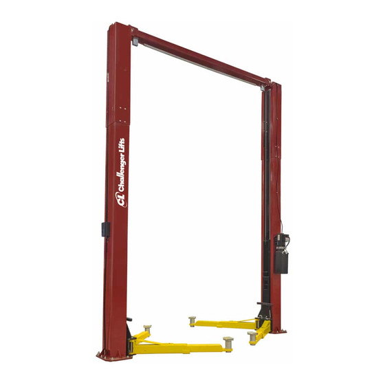
Two Post
Surface Mounted Lift
M
ODEL
10,000
LBS
2500
LBS
2311 South Park Rd Louisville, Kentucky 40219
sales@challengerlifts.com
/
502-625-0700 Fax 502-587-1933
READ THIS MANUAL COMPLETELY BEFORE
INSTALLING or OPERATING LIFT
& M
AINTENANCE
LE10
. C
APACITY
.
A
PER
RM
Web site:
www.challengerlifts.com
M
ANUAL
Rev. 12/18/18
Advertisement
Table of Contents

Related Manuals for Challenger Lifts LE10


Summary of Contents for Challenger Lifts LE10
- Page 1 & M NSTALLATION PERATION AINTENANCE ANUAL Two Post Surface Mounted Lift LE10 ODEL 10,000 APACITY 2500 2311 South Park Rd Louisville, Kentucky 40219 Email: Web site: sales@challengerlifts.com www.challengerlifts.com Office 800-648-5438 502-625-0700 Fax 502-587-1933 IMPORTANT: READ THIS MANUAL COMPLETELY BEFORE INSTALLING or OPERATING LIFT...
-
Page 2: General Specifications
Model LE10 Installation, Operation and Maintenance ENERAL PECIFICATIONS See Figure 1 LE10 LE10 w/ 2 Ft. Ext. Kit Rise Height (Screw Pads Highest Position) 74 3/4" (1899 mm) Overall Height 143 7/8" 167 7/8" (3655 mm) (4264 mm) Overall Width 131 3/4"... -
Page 3: Vertical Clearance
Model LE10 Installation, Operation and Maintenance ERTICAL LEARANCE EAD ENTIRE MANUAL BEFORE ASSEMBLING INSTALLING OPERATING OR SERVICING THIS Check the height of the area where the lift is to be EQUIPMENT installed. Clearance should be calculated based on ROPER MAINTENANCE AND INSPECTION IS the full raised height of the lift. -
Page 4: Installation
Model LE10 Installation, Operation and Maintenance ECEIVING NSTALLATION The shipment should be thoroughly inspected as AFETY EQUIREMENTS FOR NSTALLATION AND soon as it is received. The signed bill of lading is ERVICE acknowledgement by the carrier of receipt in good Refer to ANSI/ALI ALIS (current edition) condition of shipment covered by our invoice. - Page 5 Model LE10 Installation, Operation and Maintenance NCHORING 4) The anchor bolts must be installed at least 8” from any crack, edge, or expansion joint. 5) Use a concrete hammer drill with a 3/4-inch carbide bit. Tip diameter should conform to ANSI Standard B94.12-1977 (.775 to .787).
- Page 6 Model LE10 Installation, Operation and Maintenance 18) Repeat for opposite side. 23) Beginning on the idler side, attach the idler hose to the cylinder elbow fitting. Route the idler hose (long) up the backside of the column and thru the plastic guide at the top of the extension.
-
Page 7: Lock Release
Model LE10 Installation, Operation and Maintenance ELEASE 28) Install Lock Release Rod, Clevis, and Knob to the Power Column Lock using one M10 Nut. 29) Attach Mechanical Lock Release Cable Assembly to each lock pawl. See Fig. 8. Fig. 10 –... - Page 8 Model LE10 Installation, Operation and Maintenance OLUMN ECAL LACEMENT 49) Energize power unit again for 10 seconds. With a clean rag, wipe down both cylinder rods. (The 43) Clean the surface of the columns before placing cylinders are shipped with a small amount of the decals.
- Page 9 Model LE10 Installation, Operation and Maintenance Wiring Diagram FOR SINGLE PHASE ORIGINALLY CONNECTED TO A2 (Normally Open) FIELD CONNECTIONS FIELD CONNECTIONS FOR THREE PHASE FACTORY WIRED FOR 208−240V RECONNECTIONS FOR 440−480V Fig. 12 – Electrical Wiring Diagram Page 9 Rev. 12/18/18...
-
Page 10: Operation Procedure
Model LE10 Installation, Operation and Maintenance Requirements Operation, Inspection PERATION ROCEDURE Maintenance; and in the case of frame engaging lift, AFETY OTICES AND ECALS ALI/LP-GUIDE, Vehicle Lifting Points/Quick Reference Guide for Frame Engaging Lifts; in a This product is furnished with graphic safety... -
Page 11: Lifting A Vehicle
Model LE10 Installation, Operation and Maintenance IFTING A EHICLE OWERING EHICLE 1) Ensure that the lifting arms are parked, out to full 1) Ensure that the area under the vehicle is clear of drive thru position. personnel and tools. 2) Center the vehicle between the columns in the 2) Raise the vehicle until both latches are free. -
Page 12: Maintenance
Check for loose or broken parts. Check hydraulic system for fluid leaks. Check adapters for damage or excessive wear. Replace as required with genuine Challenger Lifts parts. Check lock release activation. When properly adjusted, the idler column lock should rest firmly... - Page 13 Model LE10 Installation, Operation and Maintenance Parts Breakdown Page 13 Rev. 12/18/18 LE10-IOM-A.
- Page 14 Model LE10 Installation, Operation and Maintenance Page 14 Rev. 12/18/18 LE10-IOM-A.
- Page 15 Extension Hose (2Ft.Ext. Height) IMPORTANT Replace all worn, damaged, or broken parts with parts approved by Challenger Lifts, Inc. or with parts meeting Challenger Lifts Inc. specifications. Contact your local Challenger Lifts parts distributor for pricing and availability. Call Challenger Lifts at (502) 625-0700 for the distributor in your area.
Need help?
Do you have a question about the LE10 and is the answer not in the manual?
Questions and answers