Table of Contents
Advertisement
Advertisement
Table of Contents

Related Manuals for Rohde & Schwarz R&S NRP Series


Summary of Contents for Rohde & Schwarz R&S NRP Series
- Page 1 ® R&S NRP Series Power Sensors Getting Started (>C1Ô2) 1419017002...
- Page 2 ® This manual gives an introduction to the R&S NRP series power sensors: ● ® R&S NRPxxA(N) average power sensors ● ® R&S NRPxxS(N) three-path diode power sensors ● ® R&S NRP18S-xx high-power three-path diode power sensors ● ® R&S NRPxxT(N) thermal power sensors ●...
- Page 3 Safety Instructions Instrucciones de seguridad Sicherheitshinweise Consignes de sécurité Risk of injury and instrument damage The instrument must be used in an appropriate manner to prevent electric shock, fire, personal injury or instrument damage. ● Do not open the instrument casing. ●...
- Page 4 Gefahr von Verletzungen und Schäden am Gerät Betreiben Sie das Gerät immer ordnungsgemäß, um elektrischen Schlag, Brand, Verletzungen von Personen oder Geräteschäden zu verhindern. ● Öffnen Sie das Gerätegehäuse nicht. ● Lesen und beachten Sie die "Grundlegenden Sicherheitshinweise", die als gedruckte Broschüre dem Gerät beiliegen. ●...
-
Page 5: Table Of Contents
® Contents R&S NRP Series Contents 1 Documentation Overview..............5 Getting Started Manual....................5 User Manuals.........................5 Tutorials......................... 5 Instrument Security Procedures..................5 Basic Safety Instructions..................... 6 Data Sheets and Brochures..................6 Release Notes and Open Source Acknowledgment (OSA)........6 Application Notes, Application Cards, White Papers, etc......... 6 2 For Your Safety..................8 3 Key Features...................9 4 Preparing for Use................. - Page 6 ® Contents R&S NRP Series 6.1.3 R&S NRP Toolkit for Windows..................28 Browser-Based User Interface...................30 Remote Control......................32 R&S NRPV........................32 R&S Power Viewer...................... 34 R&S Power Viewer Mobile..................37 R&S NRX........................37 R&S NRP2........................38 7 Remote Control Interfaces and Protocols......... 41 USB Interface.......................41 Ethernet Interface......................43 7.2.1...
-
Page 7: Documentation Overview
® Documentation Overview R&S NRP Series Instrument Security Procedures 1 Documentation Overview This section provides an overview of the R&S NRP series power sensor user docu- mentation. Unless specified otherwise, you find the documents on the R&S NRP series power sensor product page at: www.rohde-schwarz.com/product/nrp-a-an www.rohde-schwarz.com/product/nrp_s_sn www.rohde-schwarz.com/product/nrp18s... -
Page 8: Basic Safety Instructions
® Documentation Overview R&S NRP Series Application Notes, Application Cards, White Papers, etc. 1.5 Basic Safety Instructions Contains safety instructions, operating conditions and further important information. The printed document is delivered with the instrument. 1.6 Data Sheets and Brochures The data sheet contains the technical specifications of the R&S NRP series power sen- sor. - Page 9 ® Documentation Overview R&S NRP Series Application Notes, Application Cards, White Papers, etc. www.rohde-schwarz.com/application/nrp_s_sn www.rohde-schwarz.com/application/nrp18s Getting Started 1419.0170.02 ─ 10...
-
Page 10: For Your Safety
® For Your Safety R&S NRP Series 2 For Your Safety The R&S NRP series power sensor is designated for use in industrial, administrative, and laboratory environments. Use the R&S NRP series power sensor only for its desig- nated purpose. Observe the safety and usage instructions documented in the user manual, as well as operating conditions and performance limits stated in the data sheet. -
Page 11: Key Features
® Key Features R&S NRP Series 3 Key Features The R&S NRP series power sensors are the successors of the established R&S NRP‑Z series of RF power sensors. They provide a high-speed USB interface that constitutes both the communication port and the power supply connection. -
Page 12: Preparing For Use
® Preparing for Use R&S NRP Series Operating Conditions 4 Preparing for Use For information on safety, see: ● Chapter 2, "For Your Safety", on page 8 ● Chapter 4.2, "Operating Conditions", on page 10 4.1 Unpacking and Checking the Power Sensor Check the equipment for completeness using the delivery note and the accessory lists for the various items. -
Page 13: Important Aspects For Test Setup
® Preparing for Use R&S NRP Series Connecting to a DUT 4.3 Important Aspects for Test Setup Handling the R&S NRP33SN-V power sensor Risk of contamination Always wear clean protective gloves when handling the R&S NRP33SN-V vacuum power sensors to protect the device and its environment from contamination. Recommended bake-out procedure When the sensor is inserted in a vacuum chamber, perform vacuum baking for 100 hours at 85°C at a pressure lower than 10... -
Page 14: Connecting To A Computer
® Preparing for Use R&S NRP Series Connecting to a Computer Risk of overloading the sensor Using a power sensor at a level above its upper measuring limit can damage the sen- sor head. To avoid this risk, make sure not to exceed the test limit. The test limits specified on the type label are valid only for the supplied attenuator. -
Page 15: Setting Up A Usb Connection
® Preparing for Use R&S NRP Series Connecting to a Computer 4.5.1 Setting Up a USB Connection You can connect a R&S NRP series power sensor to a computer using the host inter- face and control it as described in Chapter 6, "Operating Concepts", on page 27. - Page 16 ® Preparing for Use R&S NRP Series Connecting to a Computer 2. On the computer, start a software application to view the measurement results. Chapter 6, "Operating Concepts", on page 27. 4.5.1.2 R&S NRP‑Z5 Sensor Hub Setup The R&S NRP‑Z5 sensor hub (high-speed USB 2.0) can host up to four R&S NRP power sensors and provides simultaneous external triggering to all connected sensors.
-
Page 17: Setting Up A Lan Connection
® Preparing for Use R&S NRP Series Connecting to a Computer = Trigger source (optional) = Triggered device (optional) 11-14 = R&S NRP‑ZK6 cable = Host interface connector = R&S NRP power sensor = Signal source Incorrectly connecting/disconnecting the R&S NRP power sensors can damage the power sensors or lead to erroneous results. - Page 18 ® Preparing for Use R&S NRP Series Connecting to a Computer Setup with a PoE Ethernet switch HOST INTERFACE TRIG2 3 V or 5 V logic OUT: min. 2 V into 50 Ω max. 5.3 V SMART SENSOR TECHNOLOGY Ethernet Switch (PoE) Figure 4-3: Setup with a PoE Ethernet switch = Signal source...
- Page 19 ® Preparing for Use R&S NRP Series Connecting to a Computer Setup with a PoE injector and a Non-PoE Ethernet switch HOST INTERFACE TRIG2 3 V or 5 V logic OUT: min. 2 V into 50 Ω max. 5.3 V SMART SENSOR TECHNOLOGY Non-PoE PoE Injector...
- Page 20 ® Preparing for Use R&S NRP Series Connecting to a Computer Setup with a PoE injector HOST INTERFACE TRIG2 3 V or 5 V logic OUT: min. 2 V into 50 Ω max. 5.3 V SMART SENSOR TECHNOLOGY PoE Injector Figure 4-5: Setup with a PoE injector = Signal source = LAN power sensor...
- Page 21 ® Preparing for Use R&S NRP Series Connecting to a Computer To set up a network Ethernet connection 1. Connect the power sensor to the network or to a single computer. By default, the power sensor is configured to use dynamic TCP/IP configuration (DHCP) and to obtain the address information automatically.
- Page 22 ® Preparing for Use R&S NRP Series Connecting to a Computer ● <serial number> is the individual serial number of the power sensor. The serial number is printed on the name plate at the rear side of the sensor. It is part of the device ID printed above the barcode: ID: 1419.0035K02 - 101441 - Zd Serial Number...
-
Page 23: Connecting To A Usb Host
® Preparing for Use R&S NRP Series Connecting to a USB Host Use hostnames to identify the sensor In networks using a DHCP server, it is recommended that you address the sensor by its unambiguous hostnames, see Chapter 4.5.2.3, "Using Hostnames", on page 19. -
Page 24: S Nrp Power Sensors Tour
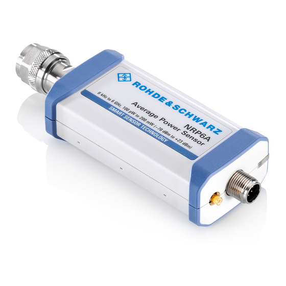
® R&S NRP Power Sensors Tour R&S NRP Series RF Connector 5 R&S NRP Power Sensors Tour This chapter provides an overview of the available connectors and LEDs of the power sensor. Figure 5-1, the USB power sensor is shown on the left, the LAN power sensor is shown on the right. - Page 25 ® R&S NRP Power Sensors Tour R&S NRP Series RF Connector Table 5-1: R&S NRPxxA(N) RF connector characteristics Power sensor Matching female con- Male connector Tightening torque nector R&S NRP6A R&S NRP6AN 1.36 Nm (12'' lbs) R&S NRP18A R&S NRP18AN Table 5-2: R&S NRPxxS(N) RF connector characteristics Power sensor Male connector...
-
Page 26: Trigger I/O Connector
® R&S NRP Power Sensors Tour R&S NRP Series Host Interface Power sensor Male connector Matching female con- Tightening torque nector R&S NRP50TN R&S NRP67T 1.85 mm R&S NRP67TN R&S NRP110T 1.0 mm 1.0 mm 0.23 Nm (2'' lbs) Table 5-5: R&S NRPxxTWG RF connector characteristics Power sensor Matching female Male connector... -
Page 27: Status Led
® R&S NRP Power Sensors Tour R&S NRP Series LAN PoE Interface 5.4 Status LED The status LED gives information about the state of the power sensor. The following states are defined: Indication State White Idle state. The sensor performs no measurement and is ready for use. Flashing white Firmware update is in progress Slow flashing white... - Page 28 ® R&S NRP Power Sensors Tour R&S NRP Series LAN PoE Interface LAN reset button The LAN reset button is used for resetting the Ethernet connection parameters of the power sensor to their default values. Power over Ethernet status LED Available only for LAN power sensor.
-
Page 29: Operating Concepts
® Operating Concepts R&S NRP Series R&S NRP Toolkit 6 Operating Concepts For operating the power sensor, you can choose from various possibilities: ● Chapter 6.2, "Browser-Based User Interface", on page 30 ● Chapter 6.3, "Remote Control", on page 32 ●... -
Page 30: R&S Nrp Toolkit For Windows
® Operating Concepts R&S NRP Series R&S NRP Toolkit Supported operating systems: ● Microsoft Windows versions – Microsoft Windows Vista 32/64-bit – Microsoft Windows 7 32/64-bit – Microsoft Windows 8/ 8.1 32/64-bit – Microsoft Windows 10 32/64-bit ● For information on other operating systems, see Chapter 6.1.1, "Versions and Downloads", on page 27. - Page 31 ® Operating Concepts R&S NRP Series R&S NRP Toolkit 3. Accept the license terms to continue with the installation. 4. Click "Next" and complete the installation process. 6.1.3.1 Components of the R&S NRP Toolkit Access: "Start" > "NRP-Toolkit" The following tools are part of the R&S NRP Toolkit for Windows. Configure Network Sensor Useful if you have troubles establishing a LAN connection with an R&S NRP LAN power sensor.
-
Page 32: Browser-Based User Interface
® Operating Concepts R&S NRP Series Browser-Based User Interface NRP Version Display Displays version information of all installed, power measurement-relevant software packages. R&S NRP‑Z Uncertainty Calculator Determines the expanded measurement uncertainty. The tool comes with a manual (PDF) that is also available in the "Start" menu. S-Parameter Update Multi Helps loading an S-parameter table into the power sensor. - Page 33 ® Operating Concepts R&S NRP Series Browser-Based User Interface Setup HOST INTERFACE TRIG2 3 V or 5 V logic OUT: min. 2 V into 50 Ω max. 5.3 V SMART SENSOR TECHNOLOGY Ethernet Switch (PoE) Figure 6-1: Setup with the web user interface = Signal source = LAN power sensor = RJ-45 Ethernet connector...
-
Page 34: Remote Control
® Operating Concepts R&S NRP Series R&S NRPV The main dialog of the web user interface opens. 4. Select the "Continuous Average" tab and perform any necessary changes. 5. Press "Measurement > ON" to start the measurement. For a detailed description of the web user interface, refer to the corresponding chapter in the user manual. - Page 35 ® Operating Concepts R&S NRP Series R&S NRPV ● R&S NRP‑ZKU cable or an R&S NRP‑Z5 sensor hub and an R&S NRP‑ZK6 cable to connect the sensor to the computer ● Windows computer with installed: – R&S NRP Toolkit V 4.16 or higher –...
-
Page 36: R&S Power Viewer
® Operating Concepts R&S NRP Series R&S Power Viewer b) Select "Zero > Select > A" (channel short name). Zeroing takes several seconds. During zeroing, a message shows the pro- gress. After completion, the message reports either success or an error ("Suc- cess"... - Page 37 ® Operating Concepts R&S NRP Series R&S Power Viewer Required equipment ● R&S NRP power sensor ● R&S NRP‑ZKU cable or an R&S NRP‑Z5 sensor hub and an R&S NRP‑ZK6 cable to connect the sensor to the computer ● Computer with installed: –...
- Page 38 ® Operating Concepts R&S NRP Series R&S Power Viewer Note: Turn off all measurement power signals before zeroing. An active measure- ment signal during zeroing causes an error. a) Switch off the measurement signal. b) Select "Sensor > Zero (Signal off) ". 4.
-
Page 39: R&S Power Viewer Mobile
® Operating Concepts R&S NRP Series R&S NRX 6.6 R&S Power Viewer Mobile The R&S Power Viewer Mobile extends the functionality of the R&S Power Viewer to Android-based devices, such as a smartphone and tablets. You can download the R&S Power Viewer Mobile free of charge from the Google Play Store. -
Page 40: R&S Nrp2
® Operating Concepts R&S NRP Series R&S NRP2 Starting a measurement 1. Preset the R&S NRX and the connected R&S power sensors. a) Press the [Preset] key. b) Tap "Preset". All parameters are set to their defaults. 2. Execute zeroing: Note: Turn off all measurement signals before zeroing. - Page 41 ® Operating Concepts R&S NRP Series R&S NRP2 Setup 3-Path Diode Power Sensor MHz to GHz, 100 pW to 200 mW (−70 dBm to +23 dBm) SMART SENSOR TECHNOLOGY Figure 6-5: Setup with an R&S NRP2 base unit 1 = Signal source 2 = R&S NRP power sensor 3 = Host interface connector 4 = R&S NRP‑ZK6 cable...
- Page 42 ® Operating Concepts R&S NRP Series R&S NRP2 b) Press the [ZERO] hardkey of the R&S NRP2. The "Zero" dialog box is displayed. c) Press the [ZERO] hardkey again to perform zeroing of all connected sensor channels ("Zero (All)") or press the appropriate softkey to select a specific sen- sor for zeroing.
-
Page 43: Remote Control Interfaces And Protocols
® Remote Control Interfaces and Protocols R&S NRP Series USB Interface 7 Remote Control Interfaces and Protocols For remote control, communication between the R&S NRP series power sensor power sensors and the controlling host is established based on various interfaces and proto- cols. - Page 44 ® Remote Control Interfaces and Protocols R&S NRP Series USB Interface The resource string represents an addressing scheme that is used to establish a com- munication session with the sensor. It is based on the sensor address and some instru- ment- and vendor-specific information.
-
Page 45: Ethernet Interface
® Remote Control Interfaces and Protocols R&S NRP Series Ethernet Interface Table 7-5: R&S NRPxxT(N) USB product IDs R&S NRP power sensor USB product ID R&S NRP18T 0x0150 R&S NRP18TN 0x0151 R&S NRP33T 0x0152 R&S NRP33TN 0x0153 R&S NRP40T 0x0154 R&S NRP40TN 0x0155 R&S NRP50T... -
Page 46: Visa Resource Strings
® Remote Control Interfaces and Protocols R&S NRP Series Ethernet Interface 7.2.1 VISA Resource Strings The VISA resource string is required to establish a communication session between the controller and the power sensor in a LAN. The resource string is a unique identifier, composed of the specific IP address of the sensor and some network and VISA-spe- cific keywords. -
Page 47: Vxi-11 Protocol
® Remote Control Interfaces and Protocols R&S NRP Series Ethernet Interface Socket communication requires the specification of the port (commonly referred to as port number) and of "SOCKET" to complete the VISA resource string with the associ- ated protocol used. The default port for socket communication is port 5025. -
Page 48: Socket Communication
® Remote Control Interfaces and Protocols R&S NRP Series Ethernet Interface The HiSLIP data is sent to the device using the "fire and forget" method with immediate return. Opposed to VXI-11, where each operation is blocked until a VXI-11 device handshake returns. -
Page 49: Index
® Index R&S NRP Series Index Android device HiSLIP R&S Power Viewer Mobile .......... 37 Protocol ............... 45 Application cards ..............6 Resource string ............44 Application notes ..............6 Hostname ................19 Brochures ................6 Instrument security procedures ........... 5 Browser-based user interface ........... - Page 50 ® Index R&S NRP Series Installation under Windows ......... 28 VXI-11 Network Configuration ..........29 Protocol ............... 45 S-parameter update ............ 30 Resource string ............44 System requirements ..........27 Uncertainty calculator ..........30 Versions ..............27 White papers ............... 6 Versions of R&S NRP software ........
Need help?
Do you have a question about the R&S NRP Series and is the answer not in the manual?
Questions and answers