Table of Contents
Advertisement
Quick Links
PC-1074
4/8 Doors Access Controller
User Manual
Ver.9.01
Pongee Industries Co., Ltd.
5F, NO. 738, Chung-Cheng Road, Chung-Ho City, Taipei, 23511, Taiwan
Tel: 886-2-82280198
Fax: 886-2-82280191
http: //www.pongee.com E-mail: pongee@pongee.com.tw
Advertisement
Table of Contents

Summary of Contents for Pongee Industries Pegasus PC-1074
- Page 1 PC-1074 4/8 Doors Access Controller User Manual Ver.9.01 Pongee Industries Co., Ltd. 5F, NO. 738, Chung-Cheng Road, Chung-Ho City, Taipei, 23511, Taiwan Tel: 886-2-82280198 Fax: 886-2-82280191 http: //www.pongee.com E-mail: pongee@pongee.com.tw...
- Page 2 1. System Synopsis The PC-1074 is designed for high-security access control and real-time monitoring environments from medium size to complex multi-site installations. It is an independent processing 4 doors access control package with metal enclosure, backup battery charger as an efficient space saving design. Suitable for applications with up to 64,000 users across a modular 1024 doors, allowing maximum flexibility for securing a growing enterprise.
- Page 3 4. System Defaults Parameter Default Setting Compare card number Disable Door release time 6 second Door monitor time 6 second Alarm time 6 second Time zone mode Disable Holiday control mode Disable Anti-pass back mode Disable Disable Check repeat reading card Printer output Disable Not recycle event buffer...
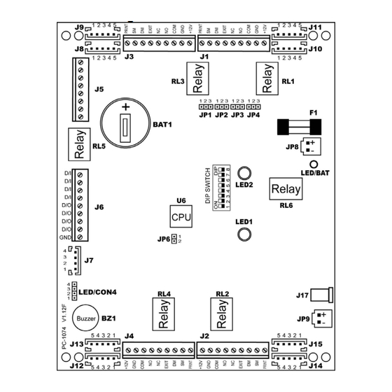
- Page 4 Connecter Function JP1~JP4 For communication interface selection For system reset For battery (UPS) JP9/ J17 Power input (Select either of one) LED1 Green light for legal access, and red light for legal access. LED2 Data ready Battery LED LED/BAT RL1~RL6 Relay 3A/250V of fuse Door 1 connecter...
- Page 5 5-4. J1~J4: 5-5. J5: 5-6. J6: The power signal sending of door monitoring、security monitoring and error times will output to DO of each door. ( 4 doors 4 DO )
- Page 6 ※D/I 3 supports fire monitor, it will be short-circuited to the GND and released 4 doors when blaze is detected, D/O 7 of fire alarm will be triggered and the same time when the doors are released. ※D/O supports Open Collector output, max. is 100mA, voltage is DC 5-12V.
- Page 7 6-2. Wiring connection with power supply ( such as electric strike lock) (J1 ~ J4) 6-3. Wiring to external reader (J8~J15)
- Page 8 6-4. Wiring to extra sensor for door monitoring or security monitoring(J1~J4) 6-5. Wiring to extra alarm...
Need help?
Do you have a question about the Pegasus PC-1074 and is the answer not in the manual?
Questions and answers