Table of Contents
Advertisement
Advertisement
Table of Contents

Related Manuals for F5 i4000 Series


Summary of Contents for F5 i4000 Series
- Page 1 Platform Guide: i2000/i4000 Series MAN-0640-02...
-
Page 3: Table Of Contents
Configure the AOM management network............22 Access the AOM Command Menu using SSH............22 Platform Installation......................... 25 About installing the i2000/i4000 Series platform.............. 25 About the quick-install rails....................25 Quick-install rail kit hardware................25 Install the rail lock brackets................... 26 About grounding the platform...................26... - Page 4 About repackaging the platform..................53 Repackage the platform..................53 Returned Material Data Security Statement................55 About returned material data security................55 About memory technologies used in F5 equipment............55 Volatile memory.....................55 Battery-backed volatile memory................55 Non-volatile memory..................... 55 About removing data from F5 components..............56 Remove sensitive data from storage drives............
-
Page 5: Platform Overview
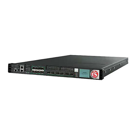
Platform Overview About i2000/i4000 Series models The i2000/i4000 Series platform is a powerful system that is designed specifically for application delivery performance and scalability. For more information, please see the data sheet at www.f5.com/pdf/products/big-ip-platforms- datasheet.pdf About the platform Before you install this platform, review information about the controls and ports located on both the front and back of the platform. -
Page 6: Hardware Included With The Platform
Platform Overview The back of the i2000/i4000 Series platform includes one power supply, one power blank, and a chassis ground terminal. Figure 3: Back view of the i2000/i4000 Series AC-powered platform 1. Power input panel 1 (AC power receptacle) 2. Power blank 3. -
Page 7: About Lcd Menus
Platform Guide: i2000/i4000 Series Type of hardware Description Network hubs, switches, or You must provide networking devices that are compatible with the connectors to connect to the network interface ports on the platform. You can use 1000/10000- platform network interfaces Megabit Ethernet switches. -
Page 8: Options Menu
LED. Option Description Display Adjusts LCD backlight brightness. Locator LED Controls the use of the chassis locator feature, which causes the F5 ® logo ball on the chassis front panel to flash on and off. Select from these options: •... -
Page 9: About Using The Lcd
Platform Guide: i2000/i4000 Series About using the LCD To manage the platform using the LCD menu options, tap the touchscreen LCD to put it into menu mode. The LCD is operational even when the Host is powered off, provided that Always-On Management and the LCD are fully booted. -
Page 10: Halt The Unit
Platform Overview 2. Tap System. The System screen displays. 3. On the System screen, tap Hard Reset. 4. Tap Confirm to reset the unit. Halt the unit You can use the touchscreen LCD to halt the unit. 1. Touch the screen to activate the LCD menus. 2. -
Page 11: Power Off/On The Unit
Platform Guide: i2000/i4000 Series Power off/on the unit You can use the touchscreen LCD to power the unit off and on. 1. Touch the screen to activate the LCD menus. 2. Tap System. The System screen displays. 3. On the System screen, swipe up to scroll down and tap Power Off or Power On. -
Page 12: Configure Lcd Brightness
Platform Overview 2. Tap Alerts. The Alerts screen displays. 3. On the Alerts screen, clear either all alerts or alerts of a specific priority: • To clear all alerts, tap Clear All. • To clear only alerts of only a specific priority, tap the priority name to view alerts with that priority, and then tap Clear. -
Page 13: Enable/Disable The Chassis Locator Led
Platform Guide: i2000/i4000 Series 3. Tap Display. The Brightness screen displays. 4. Use the left and right arrows to adjust the brightness of the LCD in real-time. 5. Click Back to return to the previous screen. Enable/Disable the chassis locator LED You can use the touchscreen LCD to enable and disable the chassis locater LED. -
Page 14: About Platform Leds
Platform Overview 4. Tap to enable or disable the chassis locator LED. About platform LEDs The behavior of the various LEDs on the platform indicate the status of the system or component. Status LED The status LED indicates the operating state of the system. State Description off/none... -
Page 15: Power 1 And Power 2 Leds
Platform Guide: i2000/i4000 Series Power 1 and Power 2 LEDs The Power 1 and Power 2 LEDs on the front of the chassis indicate the general operating state of the power supplies. Power supply Description state green solid Power supply is present and operating properly. Also indicates when the system is in power standby mode. -
Page 16: Define Custom Alerts
Platform Overview Input LED Output/Fault Condition (PWR-0307-01) Condition (PWR-0307-02 and later) green solid amber blinking Warning: FAN, OTP, OC, VOUT Warning: FAN, OTP, OC, VOUT OV/UV OV/UV green amber solid Not valid Fault: Input OV blinking green amber blinking Not valid Warning: Input OV, Input UV blinking green... -
Page 17: About Platform Interfaces
About 1GbE SFP/10GbE SFP+ interfaces The i800/i2000/i4000 Series platforms include 1GbE SFP ports (1.0-4.0 and 7.0-10.0) and 10GbE SFP ports (5.0-6.0, 11.0-12.0), in which you can use 10 GbE (SFP+) or 1GbE (SFP) transceiver modules. Important: The SFP+ ports on these platforms are not backwards compatible with SFP transceiver modules. -
Page 18: About Interface Media Type And Duplex Mode
Platform Overview The system prompt updates with the module name: user@bigip01(Active)(/Common) (tmos.net)# user@bigiq01(Active)(/Common)(tmos.net)# 3. Display the current status of all interfaces. show interface This is an example of the output that you might see when you run this command. ------------------------------------------------------------------ Net::Interface Name Status... - Page 19 Platform Guide: i2000/i4000 Series View valid media types for an interface You can use to view the valid media types for an interface. tmsh Note: This platform might not support all of the media type options that are available in tmsh 1.
-
Page 20: About Network Interface Led Behavior
Platform Overview 100baseTX full About network interface LED behavior The appearance and behavior of the network interface LEDs on the platform indicate network traffic activity, interface speed, and interface duplexity. SFP/SFP+ port LED behavior The appearance and behavior of the SFP/SFP+ port LEDs indicate network traffic activity, interface speed, and interface duplexity. -
Page 21: Create An Aom Admin User Account
Platform Guide: i2000/i4000 Series Letter Option Description • 57600 • 115200 Display platform Displays information about the AOM firmware, bootloader, and information management network configuration; chassis serial and part numbers; MAC address; power supply status; LCD status; and power status for the active console. -
Page 22: Configure The Aom Management Network
Platform Overview When the account creation is successful, a message similar to this one displays: AOM username aom-admin successfully set and enabled. Note that the AOM network must be configured via the AOM menu. 6. (Optional) Verify that the AOM admin user account is enabled and set up correctly. aom_setup_user -l A message similar to this one displays: Current AOM username: aom-admin (enabled) - Page 23 Platform Guide: i2000/i4000 Series Disable network configuration You can connect to the system's serial console to disable SSH access to AOM over the network. This does not affect console access to AOM. 1. Connect to the system using the serial console.
- Page 24 Platform Overview...
-
Page 25: Platform Installation
Platform Installation About installing the i2000/i4000 Series platform After you have reviewed the hardware requirements and become familiar with the i2000/i4000 Series platform, you can install the unit into a 19-inch rack. Important: Before you install this platform, review the environmental guidelines to make sure that you are installing the platform into a compatible rack and in the appropriate environment. -
Page 26: Install The Rail Lock Brackets
Platform Installation Quantity Hardware Rail lock brackets M3 x 6mm flathead screws, black with patch (threadlock) (for rail lock brackets) Install the rail lock brackets Be sure that the rails are installed onto the chassis before you install the rail lock brackets. The rail lock brackets secure the platform to the rack when you are using the quick-install rail kit. -
Page 27: Connect The Ground Lug To The Ground Terminal
® 2. Connect the console port to a serial console server. Depending on which F5 system you have and the console network to which you are attaching, you can use either the supplied RJ45 to DB9 console port cable or the RJ45F to RJ45M rolled serial adapter to connect the system to a serial console. - Page 28 You can now assign a management IP address to the system, and then license and provision the software. Optionally, you should run the utility. This utility collects configuration and diagnostic QKView information about your system into a single file that you can provide to F5 Technical Support to aid in troubleshooting. For more information, see support.f5.com/csp/article/K12878...
-
Page 29: Configure A Management Ip Address Using The Lcd
Platform Guide: i2000/i4000 Series Configure a management IP address using the LCD You can use the touchscreen LCD to configure the management IP address. With the management IP address, you can access the Configuration utility to configure other aspects of the product, such as the product license, VLANs, and trunks. - Page 30 Platform Installation 5. For the Type setting, tap to select either IPv4 or IPv6. 6. If you are using IPv4, you can configure the management IP address using DHCP: a) Tap DHCP. The DHCP option displays. b) Tap to set the DHCP option to ON. c) Tap Commit to save your changes.
- Page 31 Platform Guide: i2000/i4000 Series d) Tap IP Address. The IP Address screen displays. e) Use the left, right, up, and down arrows to configure the management IP address and the length of the routing prefix for the IPv4 or IPv6 management IP address.
-
Page 32: License The Platform
Once the management IP address is configured for the platform, you can use the Configuration utility to ® license the appropriate F5 software. 1. Using a Web browser, navigate to the management IP address that you assigned to the platform. -
Page 33: Platform Maintenance
DC power supply About power supplies The i2000/i4000 Series platform supports up to two AC or DC hot-swappable power supply units (PSUs). Most platforms come with only one power supply by default. Caution: Running without power supply units installed in all available bays in the platform can affect cooling and electromagnetic interference (EMI). - Page 34 Platform Maintenance When you add or replace a power supply unit in your system, be sure to verify the supply's features and that the PWR-XXXX part numbers match to ensure that you have the correct supply. On the 250W AC power supply unit, you can find the part number (PWR-0334-XX) on the top of the supply.
- Page 35 Platform Guide: i2000/i4000 Series Replace an AC power supply In the event of a power supply unit (PSU) failure, you can replace an AC PSU in your system. For a dual- supply system, you can perform the replacement without powering down the system, provided that there is at least one PSU operating during the replacement process.
- Page 36 Platform Maintenance Note: After you remove a power supply unit (PSU) from the system, it should not be installed again until five or more seconds has passed. If you apply power sooner, the supply might need to remain unpowered and out of the system for several minutes to fully discharge internally before you should try to reinstall it.
-
Page 37: About Dc Power Supplies
Platform Guide: i2000/i4000 Series 7. Ensure that the PSU is fully seated in the chassis by making sure it does not come out when gently pulled. 8. Connect an auto locking AC power cord to the power input panel on the new PSU. - Page 38 Note: The battery return terminals on the platform are in an isolated DC return (DC-I) configuration. ® Note: When you are running a redundant DC power supply configuration, F5 strongly recommends that each DC power supply unit (PSU) in the system receives power from independent DC main power sources with independent circuit breakers.
- Page 39 Platform Guide: i2000/i4000 Series Note: After you remove a power supply unit (PSU) from the system, it should not be installed again until five or more seconds has passed. If you apply power sooner, the supply might need to remain unpowered and out of the system for several minutes to fully discharge internally before you should try to reinstall it.
- Page 40 Platform Maintenance 14. Slide the new PSU into the empty slot, and push it in until the ejector latch engages and clicks. Note: While installing the supply, use care to ensure that the supply's connector does not come into contact with the rear of the chassis. 15.
-
Page 41: Environmental Guidelines
Chassis rack-mount spatial requirements The i2000/i4000 Series platforms ship with a rack mount kit to help install the system more easily. This kit requires that the rack or cabinet has certain clearances and spacing, as shown here. - Page 42 Environmental Guidelines Figure 11: Rack mounting spatial requirements for the i2000/i4000 Series platform...
-
Page 43: Guidelines For Power Supplies
Platform Guide: i2000/i4000 Series Figure 12: Detailed view of rack mounting spatial requirements Guidelines for power supplies All iSeries platforms support either single or dual power supplies. When your system includes dual power supplies, both supplies must be of the same type. To verify this, make sure that the supplies have matching base part numbers (PWR-XXXX). -
Page 44: Guidelines For Ac-Powered Equipment
Environmental Guidelines Figure 13: Example of label to check PWR-XXXX part number If you cannot read the base part number, ensure that the pull handles are both in a horizontal orientation and that the sheet metal on the power cord face for each supply has the same perforation shapes. When you add or replace a power supply unit in your system, be sure to verify the supply's features and that the PWR-XXXX part numbers match to ensure that you have the correct supply. -
Page 45: Guidelines For Dc-Powered Equipment
Platform Guide: i2000/i4000 Series Guidelines for DC-powered equipment A DC-powered installation must meet these requirements: • Use a 15 amp external branch circuit protection device to install the unit. • For permanently connected equipment, incorporate a readily accessible disconnect in the fixed wiring. - Page 46 Environmental Guidelines Figure 14: Airflow in iSeries platforms...
-
Page 47: Platform Specifications
TurboFlex Profiles are supported only in platforms running a high performance license (x800). Also, TurboFlex Profile availability varies depending on the platform series tier. For more information, see F5 Platforms: TurboFlex Profiles at support.f5.com/kb/en-us/products/big-ip_ltm/manuals/ product/f5-platform-turboflex-profiles Hardware specifications - i2000 (i2600/i2800) Series This table lists hardware specifications for i2000 (i2600/i2800 Series platforms. -
Page 48: Hardware Specifications - I4000 (I4600/I4800) Series
Platform Specifications Item Specification 16 GB AC power supply 1 x 250 W 100-240 VAC(+/- 10%) AUTO Switching Platinum 1 x NEMA 5-15P power cords DC power supply 1 x 650W DC Operating range: 44-72 VDC Minimum start up voltage: 44 VDC Note: Power supply will not start below 44 VDC. -
Page 49: Environmental Operating Specifications
Platform Guide: i2000/i4000 Series Environmental operating specifications This table lists platform environmental operating specifications. Item Specification Operational temperature 32 to 104°F (0 to 40°C) Operational relative humidity 5% to 85% (40°C) non-condensing Up to 93% (40°C) non-condensing for a maximum of 96 hours Non-operational temperature -40 to 158°F (-40 to 70°C) -
Page 50: Safety Requirements
Platform Specifications Item Single power supply Dual power supply Idle power draw (AC power) 110VAC input: 95W 110VAC input: 95W 220VAC input: 90W 220VAC input: 95W Typical power draw (AC power; 50% load; 110VAC input: 130W 110VAC input: 130W temp 25°C) 220VAC input: 125W 220VAC input: 130W Typical power draw (DC power;... -
Page 51: Acoustic And Altitude Specifications
Platform Guide: i2000/i4000 Series As Telecommunication Network Equipment (TNE) in Both Telecom Centers and Other than Telecom Centers per (as applicable): ETSI EN 300 386 V1.6.1 (2012) EN 55032:2012/AC:2013 EN 61000-3-2:2014 EN 61000-3-3:2013 As Information Technology Equipment (ITE) Class A per (as applicable):... - Page 52 Platform Specifications In accordance with China's Management Methods for the Restriction of the Use of Hazardous Substances in Electrical and Electronic Products #32, the following information is provided regarding the names and concentration levels of toxic substances or hazardous substances that may be contained in the following product relative to the standards set by the Standardization Administration of the People's Republic of China.
-
Page 53: Repackaging Guidelines
You can perform a disk erase operation to erase all sensitive data from storage drives (for example, solid- state drives and hard disk drives) before you return a platform to F5. For more information, see F5 Platforms: Essentials at support.f5.com/kb/en-us/products/big-ip_ltm/manuals/... - Page 54 Repackaging Guidelines...
-
Page 55: Returned Material Data Security Statement
Returned Material Data Security Statement About returned material data security ® Follow these data security guidelines when returning equipment to F5 for reprocessing or repair. The guidelines include reprocessing procedures and optional customer-end procedures. About memory technologies used in F5 equipment ®... -
Page 56: About Removing Data From F5 Components
For components that contain sensitive customer data and cannot be removed from your F5 system, you can take optional steps to remove the data from these components before you return the system to F5 for processing. Remove sensitive data from storage drives ®... -
Page 57: Legal Notices
2018, F5 Networks, Inc. All rights reserved. F5 Networks, Inc. (F5) believes the information it furnishes to be accurate and reliable. However, F5 assumes no responsibility for the use of this information, nor any infringement of patents or other rights of third parties which may result from its use. - Page 58 Legal Notices Any modifications to this device, unless expressly approved by the manufacturer, can void the user's authority to operate this equipment under part 15 of the FCC rules. Canadian Regulatory Compliance This Class A digital apparatus complies with Canadian ICES-003. Standards Compliance This product conforms to the IEC, European Union, ANSI/UL and Canadian CSA standards applicable to Information Technology products at the time of manufacture.
- Page 59 Index Index China material content listing, See China RoHS Directive 10G interfaces, See SFP+ interfaces. standards. 10GbE interfaces, See SFP+ interfaces. China RoHS Directive standards Configuration utility about managing interfaces licensing the platform AC power supplies viewing status of all interfaces and hot swapping cooling system AC-powered equipment...
- Page 60 Index LCD menus about halt operation Alerts menu options halting the unit and Options menu options using the LCD Setup menu options hard disk drives (HDDs) specifications 47, System menu options hard-wired failover hardware network interface AC-powered equipment LEDs DC-powered equipment about hardware requirements alarm...
- Page 61 Index power supply units (PSUs) (continued) replacing a DC power supply unit pass-through adapter, See RJ45F to RJ45M rolled serial replacing an AC power supply unit adapter. powering off/on the unit pinouts for cables using the LCD specifications platform about about grounding qkview utility about installing...
- Page 62 Index serial failover serial port setting baud rate ventilation serial port baud rate diagram configuring using the LCD SFP ports and LEDs SFP+ interfaces warnings about environmental SFP+ ports warnings, environmental and LEDs See also China RoHS Directive standards. specifications China RoHS for acoustic levels for airflow...
Need help?
Do you have a question about the i4000 Series and is the answer not in the manual?
Questions and answers