Table of Contents
Advertisement
Advertisement
Table of Contents

Related Manuals for TrolMaster Aqua-X NFS-1


Summary of Contents for TrolMaster Aqua-X NFS-1
- Page 1 Aqua-X Controller...
-
Page 2: Table Of Contents
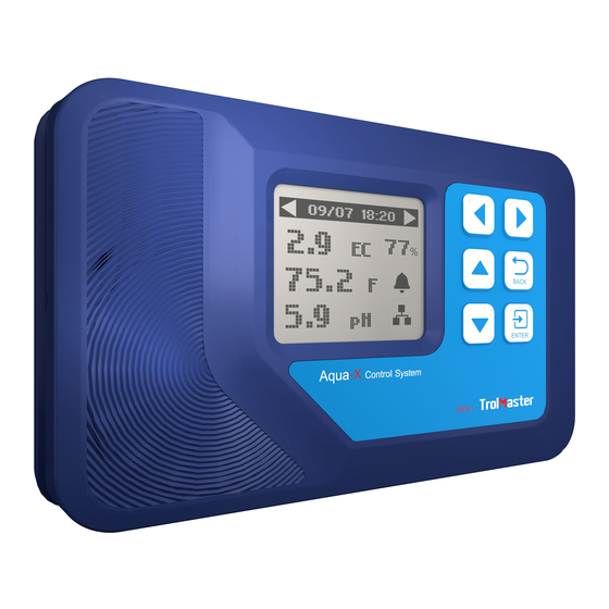
PLEASE READ FIRST INTRODUCTION Aqua-X Irrigation Controller is a pioneering and innovational hydroponic Congratulations on your purchase of the NFS-1 Controller . This unit irrigation control system. This smartphone App based system can control is an efficient way to fully control your irrigation systems. To ensure safety, please read this manual carefully before installation and follow up to 30 outputs (24V or 110V) and monitor the pH, EC and water the instructions herein. -
Page 3: Facts
COMPONENTS FACTS Here are some important things to consider when using the Aqua-X Irrigation Controller . Each set of Aqua-X Irrigation Controller can connect up to 30 outputs (24V or 110V) and monitor the pH value, EC value and water temperature of nutrient. -
Page 4: Connections
CONNECTIONS INSTALLATION Determine where to locate the main controller. The controller comes with a simple to use DIN type bracket. Pull the 4 tabs outward to release the bracket from the unit, mount the bracket to a wall or surface, place the unit back on the bracket and press the 4 tabs back in to lock the unit in place. - Page 5 CONNECTIONS CONTINUED... 5. Sensors Connection: Connect the Sensor Board to the Aqua-X with a round-headed cable (male-to-male). Connect the pH Sensor and EC/Temp Sensor to the 1. Power Connection: corresponding connector on the Sensor Board. Connect the plug-in power supply to the power (DC) connector on the far left.
-
Page 6: Buttons
If it is the first time you have used the NFS-1Controller , when you power on the NFS-1 Controller , the Welcome screen / page will display and remind user to press “ENTER” to set system time. Welcome to TrolMaster Aqua-x Control Sustem Aqua-x Control System Press “ENTER”... -
Page 7: Main Menu
Water Detector. Internet Connected Hot-plug is not recommended for the MicroSD card on the main NOTE: NOTE: Download the TrolMaster App from App Store or Google page. Damage to the files within the MicroSD card is a possible result. Play. -
Page 8: Setting Page
110V BOARD SETTING SETTING PAGE When the RJ12 cable is not correctly connected to the corresponding 110V CONTROL port or the 110V Control Board is not connected to the power supply, the LCD screen will show “No 110V Board Online”. Alarm Message Please make sure the RJ12 cable is correctly connected and power on . - Page 9 a. By schedule: When the Control Board is selected, press ENTER button and the 1st Once the “By schedule” setting is selected, user can press ENTER button output will be highlighted and blinking. Press LEFT, RIGHT, UP or to activate the setting for the 1 line of total 12 lines of schedules. The DOWN button to select the output such as 110V A1.
- Page 10 b. By recycle: 110 V 110 V Once the “By recycle” setting is selected, user can press UP or DOWN Start 08:00 Start 08:00 Setting saved button to select “Start”, “On time”, “Off time” & “Times” for change. On time 05m 10s On time 05m 10s...
-
Page 11: Water Detector Setting
a.Leak Sensor (Leak Detection Mode) WATER DETECTOR SETTING The default function of Water Detector (WD-1) is to do leak detection and the symbol is a triangle shown in the Aqua-X Controller. When WD-1 detects water leakage, it will send alarm message to your Aqua-x Controller Water Detector Smartphone one minute later. - Page 12 b. Assignment (Output Assigned Mode) Water Detector The default mode of Water Detector is in Leak Sensor (Leak Detection 110 V 110 V Mode). You can change the Leak Detection Mode (Leak Sensor) into Output assigned Mode (Assignment) as below processes. As one Water Detector 1 Detector can be assigned to only one output on any Control Board, Setting saved...
-
Page 13: Alarm Settings
ALARM SETTING User can also press DOWN button to select the MAX value directly for change if keeps unchanged for the MIN value. The setting of MAX On the Setting page, press DOWN button to select the Alarm Setting. Press ENTER value is similar to setting of MIN value. -
Page 14: Alarm Settings
SYSTEM SETTING c. pH Alarm: When the pH Alarm is selected, press the ENTER button to enter the On the Setting page, press DOWN button to select the System Setting. pH Alarm setting page. The LCD screen will display the MIN value and Press ENTER button and the LCD screen will display five Settings for MAX value. - Page 15 b.Time Setting: c . Serial Number: When the Time Setting is selected, press ENTER button and the LCD When the Serial Number column is selected, press ENTER button display will show the default time if it’s the first time to use this unit. The and the LCD display will show the QR code and serial number.
- Page 16 e. Calibration: d . System Reset: When the Calibration column is selected, press ENTER button and When the System Reset column is selected, press ENTER button and the LCD display will show Calibrate EC, Calibrate pH7.0, Calibrate the LCD display will show Device Reset, Factory Reset, Firmware pH4.0.
-
Page 17: General Information
f. Emergency Stop GENERAL INFORMATION The Emergency Stop function can be selected when there is abnormal condition found on the Control Boards. Press the DOWN button to WARRANTY select “Emergency Stop” and then press the ENTER button to confirm Aqua-X Irrigation Controller (NFS-1) only uses high quality components. your selection. -
Page 18: Troubleshooting
By registering your NFS-1 Irrigation controller on our website www.trolmaster.com, we can notify you when an update is available. We will not sell, rent or share your personal information. The Aqua-X Irrigation Controller (NFS-1) is... -
Page 19: Specifications
SPECIFICATIONS Please make sure that the network path is workable (you can check whether the network Cannot connect to the network. cable is workable to any Internet-connected device). Please do not pull out the microSD card on the The microSD card is damaged. main interface (displaying current temperature, pH, EC values).
Need help?
Do you have a question about the Aqua-X NFS-1 and is the answer not in the manual?
Questions and answers