
Related Manuals for Hitachi PLC


Summary of Contents for Hitachi PLC
-
Page 1: Table Of Contents
Getting Started Hitachi PLC Contents Page Introduction Hitachi PLC Technical Specifications Setting up Configuration Wiring Programming... - Page 2 EH-150 and MICRO-EH has a 32 bits RISC microprocessor called “Super H”. Compact size The compact PLC has more capabilities with high reliability, and saves more space and cost. Open network EH-150 series has Profibus DP master/slave modules and DeviceNet master/slave modules, which will increase application range.
-
Page 3: Introduction
How it works? The PLC has a CPU. The CPU executes (scans) a user program. When the CPU reaches the end of the program, the CPU will return to the program top and execute again, this process is continuous. In every cycle, input data is read, and output data is written once each. - Page 4 OFF. Retentive Data memory (SRAM) Start the PLC by PC or RUN switch on the PLC PLC starts operation according to the user program. CPU module FLASH memory Program memory (SRAM) Data memory (SRAM) Retentive Data memory (SRAM) ç...
-
Page 5: Hitachi Plc
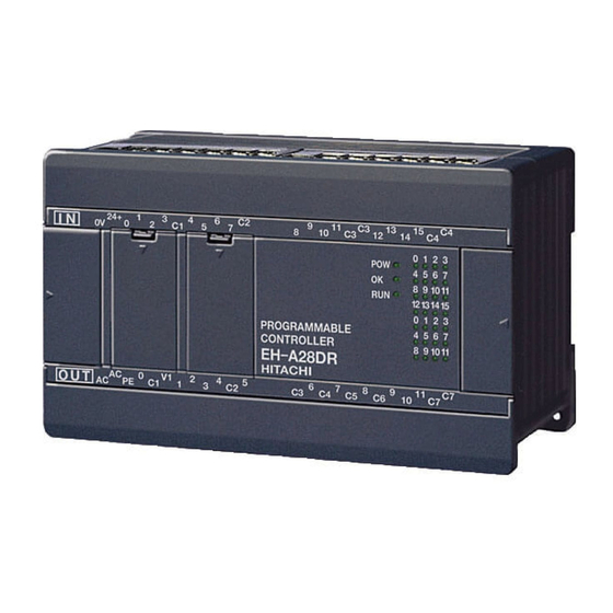
2. Hitachi PLC System design Hitachi has a compact type PLC “MICRO-EH” and modular type PLC “EH-150”. Input terminal n MICRO-EH LED indication Expansion connector è RUN RUN/STOP switch Potentiometer × 2 Communication Port 1 (RS-232C) Output terminal Communication port 2... - Page 6 Before going into the Hitachi PLC details, it is important to understand the numbering system of the PLC. Electric devices like PLC’s can handle only digital data. The minimum unit of digital data is a “bit”. 1 bit has two states, 0 or 1.
- Page 7 I/O data types Hitachi PLC’s handles the following I/O. Word Double Word (for Digital data, etc) (for Analog data, etc) X ¨¨¨¨ [D] WX ¨¨¨ [H] DX ¨¨¨ [H] External Input Y ¨¨¨¨ [D] WY ¨¨¨ [H] DY ¨¨¨ [H]...
- Page 8 n Internal I/O Internal I/O (R, WR, M, WM, etc.) means data memory. This data memory area can be read or written freely for flags, parameters, set point values or calculation depending on your program. [ R, WR ] Note : “R” and “WR/DR” are physically separated memory areas. DR 1 WR 0 WR 1...
- Page 9 I/O address of MICRO-EH The I/O address of MICRO-EH is fixed. n 10/14/28 points DI × 6 DI × 8 DI × 16 X0 – X5 X0 – X7 X0 – X15 Input DO × 4 DO × 6 DO × 12 Y100 –...
- Page 10 I/O address of EH-150 The I/O address of EH-150 depends on the module location and I/O type. X ¨ ¨ ¨¨ WX ¨ ¨ ¨ [ Bit ] [ Word ] Word number Bit number (decimal) Slot number (0 - 7) Slot number (0 - 7) Unit number (0 - 1) Unit number (0 - 1)
-
Page 11: Technical Specifications
Special internal registers R, WR The special internal registers are some flags, diagnostic information and parameter setting area to operate the PLC easily and flexibly. The following list is a part of this area and error code in WRF000. Address... -
Page 12: Setting Up
4. Setting up Baud rate for PLC n MICRO-EH Configure baud rate for communication port 1 and 2. For normal use, set the dip switch 1 ON. The port 1 will then be available for programming with 19.2kbps. Behind the cover Port No. - Page 13 n EH-150 Configure baud rate for communication port 1 and 2. For normal use, set the dip switch 1, 3, 5 all ON, and the toggle switch ON. Both ports will then be available for programming with 19.2kbps. CPU module Toggle switch Dip switch 19.2 kbps for both ports...
-
Page 14: Configuration
Ø Operation parameters Ø Retentive area, etc. I/O configuration n MICRO-EH The I/O configuration of MICRO-EH is fixed for each model. This table can be read out from the PLC when on-line. 10, 14, 28 points basic module 28 points... - Page 15 EH-150 Since the module configuration of EH-150 depends on the user, the I/O configuration table (module configuration table) must be declared in the PC. This table can be read out from PLC when on-line. EH-XD64 EH-AX8V [ I/O configuration table in PC ]...
- Page 16 Operation parameters Several optional parameters are available. Configure if necessary. Operation parameters Default Enable RUN input Disable Set the address Max. scan time 100 ms Set the time Operation mode in wrong I/O configuration STOP Operation mode in expansion unit error STOP Operation mode in remote unit error STOP...
-
Page 17: Wiring
6. Wiring Wiring diagram for some modules are shown below. Implement wiring based on these drawings for other MICRO-EH also. Each I/O module for EH-150 has a wiring label at the terminal block. Note : All DC inputs can be connected as either positive or negative logic. MICRO-EH [EH-D10DTP] EH-150 [EH-YTP16] RUN input... -
Page 18: Programming
Basically input “X” is used for the contact, and output “Y” is used for the coil. The internal I/Os “R”, “M” can be used for both cases depending on your program. (Y can work as a contact.) Hitachi PLC handles the following I/O types. A contact... - Page 19 Y100 Y100 Y100 Y100 Y100 Y100 Edge detection (á) : DIF Y100 DIF 0 Y100 1 scan time Edge detection (â) : DFN Y100 DFN 0 Y100 1 scan time Set/Reset coil Y100 Y100 Y100 Internal memory R, M can be used instead of X and Y. &...
- Page 20 ON delay timer : TD LADDER EDITOR 0.1s TD 0 TD 0 Y100 TD 0 Pro-H (LD) Y100 1.2s TD 0 0.1s Y100 TC 0 Pro-H (FBD) * TC is a word data counting 0 up to 65,535. TD 0 Y100 0.1s Single Shot timer : SS...
- Page 21 Comparison box LADDER EDITOR H3000 < Y100 WX 3 H3000 WX 3 Pro-H (LD) WX 3 GT 0 0.1s Y100 Y100 16#3000 While WX 3 exceeds H3000, Y100 is ON. Pro-H (FBD) GT 0 WX 3 Y100 0.1s 16#3000 * GT : Greater Than Inline box Many commands are available Basic commands : 35 ∼...