Table of Contents
Advertisement
Quick Links
Overview
General Description
The Shure ANI4IN Audio Network Interface converts 4 analog audio channels
into independent digital audio channels on a Dante™ network. Microphone,
auxiliary, and line-level devices are supported, with adjustable gain and +48V
phantom power for each channel. In networked conferencing systems, the
Audio Network Interface provides a simple way to connect analog equipment
onto the audio network, such as wireless microphones. The web application
Hardware and Installation
Hardware
Block Connector Model:
sig/clip
1
2
3
4
XLR Model:
©2017 Shure Incorporated
controls signal routing and channel settings from any computer connected
to the same network.
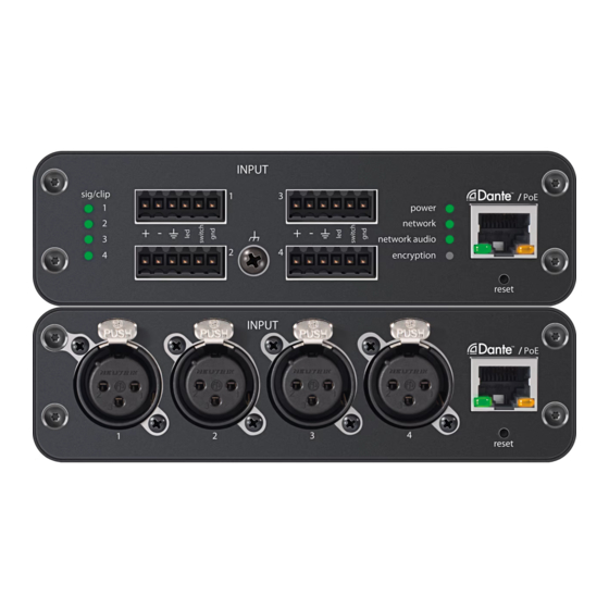
Model Variations
ANI4IN-XLR: Four XLR inputs (balanced audio only)
ANI4IN-BLOCK: Four 6-pin block connector inputs (balanced audio and
logic connections)
INPUT
1
3
2
4
Audio Network Interface
power
network
network audio
encryption
reset
ANI4IN
PoE
1/28
Advertisement
Table of Contents

Related Manuals for Shure ANI4IN Series


Summary of Contents for Shure ANI4IN Series
- Page 1 General Description The Shure ANI4IN Audio Network Interface converts 4 analog audio channels Model Variations into independent digital audio channels on a Dante™ network. Microphone, auxiliary, and line-level devices are supported, with adjustable gain and +48V ANI4IN-XLR: Four XLR inputs (balanced audio only) phantom power for each channel.
- Page 2 ANI4IN Audio Network Interface Shure Incorporated INPUT reset ① Input Signal Clip Indicators Each indicator corresponds to a single input channel. If the LED turns red, attenuate the level from the source device to prevent clipping at the input stage.
-
Page 3: Power Over Ethernet (Poe)
ANI4IN Audio Network Interface Shure Incorporated ③ Chassis Ground Screw Provides an optional connection for microphone shield wire to chassis ground Note: only applies to block connector version ④ LED Indicators Power: Power over Ethernet (PoE) present Note: Use a PoE injector if your network switch does not supply PoE. -
Page 4: Rack Ear Configuration
ANI4IN Audio Network Interface Shure Incorporated Device 1 Device 2 Device 3 Align the holes as shown for securing up to three devices in the 19" rack tray. Rack Ear Configuration A combination of up to 3 Audio Network Interfaces can be mounted in a single 19-inch rack space. The adjustable rack ears support mounting in a standard equipment rack or underneath a table. -
Page 5: Signal Flow And Connections
Setting up the Audio Network Shure networked conferencing systems are comprised of Microflex Advance microphones and network interfaces, which operate entirely on a Dante™ network. Additional hardware, including network switches, computers, loudspeakers, and audio processors are described in the hardware component index. - Page 6 This diagram shows the entire signal path through a networked conference system. Signals from the near end and far end are exchanged through an audio processor connected to a phone system, or through a computer connected to the internet. Analog microphones connect to the network through the Shure ANI4IN, while loudspeakers connect through the Shure ANI4OUT.
- Page 7 Expanded Control for Analog Devices Analog devices that are connected to the network through a Shure network interface (ANI4IN/ANI4OUT) benefit from additional remote control: Volume levels, equalization, and signal routing are managed through the web application. For example, adjusting loudspeaker volume or muting a wired microphone, which would normally be done from the hardware, can now be controlled remotely over the network.
-
Page 8: Connections And Signal Flow
ANI4IN Audio Network Interface Shure Incorporated Connections and Signal Flow ⑤ Computer INPUT sig/clip power network network audio encryption reset ① MX396 ② MX392 control audio gain power ULXD4 ENTER Digital Wireless Receiver EXIT SCAN push ④ Network Switch ③ ULX-D Receiver ①... -
Page 9: Example Scenario
ANI4IN Audio Network Interface Shure Incorporated 1 + 2 3 + 4 3 + 4 1 +2 1 + 2 + 3 + 4 Example Scenario A common application that requires summing is a video conference where there are multiple microphones. When a device (a computer running conferencing software and Dante™... -
Page 10: Software Installation, Management, And Security
Software Installation and Device Discovery The Shure Web Device Discovery application is used to access the web application for a Shure device. The web application opens in a web browser to provide comprehensive device management. Any computer networked to the device can access the GUI with this application. -
Page 11: Channel Utilities
The format for Shure device’s firmware is MAJOR.MINOR.PATCH. (Ex. 1.6.2 where 1 is the Major firmware level, 6 is the Minor firmware level, and 2 is the Patch firmware level.) At minimum, devices that operate on the same subnet should have identical MAJOR and MINOR release numbers. -
Page 12: Equalizer Applications
ANI4IN Audio Network Interface Shure Incorporated Parametric: Attenuates or boosts the signal within a customizable frequency range Low Cut: Rolls off the audio signal below the selected frequency Low Shelf: Attenuates or boosts the audio signal below the selected frequency... -
Page 13: Custom Presets
The entries are stored in the internal memory, and are not cleared when the device is power-cycled. The Export feature creates a CSV (comma separated values) document to save and sort the log data. Refer to the log file for details when troubleshooting or consulting with Shure Systems Support. To view the event log: 1. -
Page 14: Levels And Metering
ANI4IN Audio Network Interface Shure Incorporated Levels and Metering Adjusting Input Levels Input Levels Before you begin, verify that levels from the analog devices with adjustable output levels are operating at nominal levels. The analog gain adjusts the level of the audio signal before it is converted from analog to digital. It is adjustable in 3 dB increments, with up to 51 dB total gain. - Page 15 ANI4IN Audio Network Interface Shure Incorporated Analog gain adjustment (affects pre-fader metering) Pre-fader Post-fader Digital gain adjustment (affects post-fader metering) Pre-Fader (Analog Input Level) Pre-fader metering displays the signal level before it reaches the digital gain fader, so that input signal levels can be optimized for each channel. Analog gain adjustments affect the meter when set to pre-fader, but the digital gain adjustments do not.
-
Page 16: Logic And Control Systems
(such as an echo canceller or control system) that supports Ethernet command strings. ® In this diagram, Shure MX392 and MX396 Microflex microphones are connected the audio network interface. The mute button on each microphone sends a logic signal (switch) to mute other audio equipment. -
Page 17: Command Strings (Common)
ANI4IN Audio Network Interface Shure Incorporated All channels 1 through 4 Individual channels Command Strings (Common) Get All Where x is ASCII channel number: 0 through 4. Command String: Use this command on first power on to update the < GET x ALL >... - Page 18 ANI4IN Audio Network Interface Shure Incorporated Get Device ID Command String: The Device ID command does not contain the x channel character, as it is for the entire ANI4IN. < GET DEVICE_ID > Where yyyyyyyyyyyyyyyyyyyyyyyyyyyyyyy is 31 ANI4IN Response: characters of the device ID. The ANI4IN always <...
- Page 19 ANI4IN Audio Network Interface Shure Incorporated ANI4IN Response: Where yyyy takes on the ASCII values of 0000 to 1280. < REP x AUDIO_GAIN_HI_RES yyyy > Get Analog Audio Gain Command String: Where x is ASCII channel number: 0 through 4.
- Page 20 ANI4IN Audio Network Interface Shure Incorporated ANI4IN Response: The ANI4IN will respond with one of these strings. < REP x AUDIO_MUTE ON > < REP x AUDIO_MUTE OFF > Flash Lights on ANI4IN Command String: Send one of these commands to the ANI4IN. The <...
- Page 21 ANI4IN Audio Network Interface Shure Incorporated Command String: < GET x PHANTOM_PWR_ENABLE > ANI4IN Response: The ANI4IN will respond with one of these strings. < REP x PHANTOM_PWR_ENABLE ON > < REP x PHANTOM_PWR_ENABLE OFF > Turn on Phantom Power Command String: <...
- Page 22 ANI4IN Audio Network Interface Shure Incorporated Command String: < GET INPUT_METER_MODE > ANI4IN Response: The ANI4IN will respond with one of these strings. < REP INPUT_METER_MODE PRE_FADER > < REP INPUT_METER_MODE POST_FADER > Set Input Meter Mode (firmware > v2.0) Command String: <...
- Page 23 ANI4IN Audio Network Interface Shure Incorporated where x is channel number, defined in GET ANI4IN Response: command. where nnn is audio level in the range of < REP x AUDIO_IN_PEAK_LVLnnn > 000-060 Get Network Audio Device Name Command String: < GET NA_DEVICE_NAME >...
-
Page 24: Networking And Dante
This device can connect with up to two Dante devices. The Shure MXA310, ANI22, ANIUSB-MATRIX and ANI4IN support multicast transmission. This means that flows can transmit to multiple devices -- as many as the network can support. If using unicast flows, each of these devices can connect with up to two Dante receiver devices. -
Page 25: Important Product Information
Note: The maximum accepted payload 140 bytes. Any content is allowed. 2. The Shure device will send a response packet over unicast UDP to the controller, using a destination UDP port identical to the source port of the query packet. The payload of the response packet follows this format:... - Page 26 ANI4IN Audio Network Interface Shure Incorporated Phantom Power selectable per channel +48 V Logic Connections (Block connectors only) Sent as Ethernet command strings LED(+5 V), Switch Polarity Non-inverting, any input to any output Output (1) RJ45 Power Requirements Power over Ethernet (PoE), Class 0...
-
Page 27: Ip Ports And Protocols
ANI4IN Audio Network Interface Shure Incorporated 113 dB Equivalent Input Noise 20 Hz to 20 kHz, A-weighted, input terminated with 150Ω Analog Gain Setting= +0 dB -93 dBV Analog Gain Setting= +27 dB -119 dBV Analog Gain Setting= +51 dB... -
Page 28: Furnished Accessories
*These ports must be open on the PC or control system to access the device through a firewall. †These protocols require multicast. Ensure multicast has been correctly configured for your network. Shure Incorporated 5800 West Touhy Avenue Niles, IL 60714-4608 USA Phone: +1-847-600-2000 Email: info@shure.com 28/28...
Need help?
Do you have a question about the ANI4IN Series and is the answer not in the manual?
Questions and answers