Table of Contents
Advertisement
Quick Links
Advertisement
Table of Contents

Summary of Contents for Shenzhen Mindray Bio-Medical Electronics Co., Ltd. DC-N2
- Page 1 DC-N2/DC-N2T/DC-N2S Diagnostic Ultrasound System Operator’s Manual [Basic Volume]...
-
Page 3: Table Of Contents
Contents Intellectual Property Statement ......................I Responsibility on the Manufacturer Party ..................I Warranty ............................II Exemptions ........................... II Customer Service Department ..................... II Important Information ........................III About This Manual ........................... III Notation Conventions ........................ - Page 4 3.3.2 Powering OFF ....................... 3-6 3.4 Display Adjusting ........................3-6 3.4.1 Position ......................... 3-6 3.4.2 Tilting Angle ........................3-6 3.4.3 Brightness and Contrast ....................3-7 3.5 Connecting / Disconnecting a Probe ..................3-7 3.5.1 ...
- Page 5 5.6.3 Color Mode Image Optimization ................. 5-12 5.7 Power Mode Image Optimization ..................5-16 5.7.1 Basic Procedures for Power Mode Imaging ............... 5-16 5.7.2 Power Mode Image Parameters ................. 5-16 5.7.3 Power Mode Image Optimization ................5-16 5.8 ...
- Page 6 8.1.3 Adding Comments ......................8-3 8.1.4 Moving Comments ......................8-4 8.1.5 Editing Comments ......................8-4 8.1.6 Deleting Comments ...................... 8-4 8.2 Body Mark ..........................8-5 8.2.1 Body Mark Operation Procedures ................8-5 8.2.2 ...
- Page 7 10.5 Structured Report ......................10-16 10.6 DICOM Task Manager ...................... 10-16 11 Setup ...........................11-1 11.1 System Preset ........................11-1 11.1.1 Region ........................11-2 11.1.2 General ........................11-2 11.1.3 Image Preset ......................11-4 11.1.4 ...
- Page 8 14.4.2 MI/TI Display ....................... 14-2 14.5 Acoustic Power Setting ...................... 14-3 14.6 Acoustic Power Control ...................... 14-3 14.7 Acoustic Output ........................14-4 14.7.1 Derated Ultrasonic Output Parameters ..............14-4 14.7.2 Limits of Acoustic Output .................... 14-4 14.7.3 ...
-
Page 9: Intellectual Property Statement
©2013-2014 Shenzhen Mindray Bio-Medical Electronics Co., Ltd. All rights Reserved. For this Operator’s Manual, the issue date is 2014-04. Intellectual Property Statement SHENZHEN MINDRAY BIO-MEDICAL ELECTRONICS CO., LTD. (hereinafter called Mindray) owns the intellectual property rights to this Mindray product and this manual. This manual may refer to information protected by copyright or patents and does not convey any license under the patent rights or copyright of Mindray, or of others. -
Page 10: Warranty
It is important for the hospital or organization that employs this equipment to carry out a reasonable service/maintenance plan. Neglect of this may result in machine breakdown or personal injury. Warranty THIS WARRANTY IS EXCLUSIVE AND IS IN LIEU OF ALL OTHER WARRANTIES, EXPRESSED OR IMPLIED, INCLUDING WARRANTIES OF MERCHANTABILITY OR FITNESS FOR ANY PARTICULAR PURPOSE. -
Page 11: Important Information
About This Manual This operator’s manual describes the operating procedures for this diagnostic ultrasound system DC-N2/DC-N2T/DC-N2S and the compatible probes. To ensure safe and correct operations, carefully read and understand the manual before operating the system. Notation Conventions In this operator’s manual, the following words are used besides the safety precautions (refer... -
Page 12: Operator's Manuals
Operator’s Manuals Please read the operator’s manuals carefully before operating the system. You may receive multi-language manuals in compact disc or paper. Please refer to English manual for latest information and register information. The content of the operator manual, such as screens, menus or descriptions, may be different from what you see in your system. -
Page 13: Software Interfaces In This Manual
[Items in Menu] [Items in Submenu]: Selects a submenu item following the path. [Dyn Rng (Value)]: Indicates menu items with parameter, (value) shows the current value of the item. Product Differences Product Model B-histogram B-Profile √ √ DC-N2 √ DC-N2T × √ DC-N2S ×... -
Page 15: Safety Precautions
Safety Precautions Safety Classification According to the type of protection against electric shock: CLASS I EQUIPMENT + Internally Powered ME Equipment According to the degree of protection against electric shock: Type-BF applied part According to the degree of protection against harmful ingress of water: Main unit: IPX0 Probes: IPX7 Footswitch: 1-pedal type belongs to IPX8, 2-pedal and 3-pedal type belong to IP68. -
Page 16: Meaning Of Signal Words
Meaning of Signal Words DANGER WARNING CAUTION In this manual, the signal words" ”, “ ”, “ ”, “NOTE” and "Tips" are used regarding safety and other important instructions. The signal words and their meanings are defined as follows. Please understand their meanings clearly before reading this manual. -
Page 17: Safety Precautions
Safety Precautions Please observe the following precautions to ensure patient and operator’s safety when using this system. DO NOT use flammable gasses, such as anesthetic gas or DANGER: hydrogen, or flammable liquids such as ethanol, near this system, because there is danger of explosion. Do connect the power plug of this system and power plugs WARNING: of the peripherals to wall receptacles that meet the ratings... - Page 18 DO NOT allow the patient to contact the live parts of the ultrasound system or other devices, e.g. signal I / O ports. Electric shock may occur. Do not use an aftermarket probe other than those specified by Mindray. The probes may damage the system causing a profound failure, e.g.
- Page 19 19. If the battery cannot be automatically maintained in a fully usable condition, please conduct periodic checking of the battery. 20. The ultrasound system use a mains plug as isolation means to the mains power supply. Please do not posite the ultrasound system in a place difficult to operate the mains plug.
- Page 20 Do not connect this system to outlets with the same circuit breakers and fuses that control the current of devices such as life-support systems. If this system malfunctions and generates overcurrent, or when there is an instantaneous current at power ON, the circuit breakers and fuses of the building ’...
- Page 21 16. Do not use gel, disinfectant, probes, probe sheath or needle-guided brackets that are not compatible with the system. 17. Read the Acoustic Output Principle in the operation manual carefully before operate this system on clinical examination. 18. Please use the ultrasound gel compliant with the relevant local regulations.
- Page 22 Electrical and mechanical performance may be degraded due to long usage (such as current leakage or distortion and abrasion), the image sensitivity and precision may become worse too. To ensure optimal system operations, it is recommended that you maintain the system under a Mindray service agreement.
- Page 23 Do not use the carrying case for storing the transducer. If the carrying case is used for storage, it may become a source of infection. It is required to practice ALARA when operating ultrasound system. Minimize the acoustic power without compromising the quality of images.
-
Page 24: Latex Alert
2. Ambient conditions: To prevent the transducer from being damaged, do not use it where it will be exposed to: Direct sunlight or X-rays Sudden changes in temperature Dust Excessive vibration Heat generators Use the probes under the following ambient conditions: Ambient temperature: 0°C ~ 40°C Relative humidity: 30% to 85% (no condensation) Atmospheric pressure: 700 hPa ~ 1060 hPa... -
Page 25: Warning Labels
Warning Labels The warning labels are attached to this system in case of potential hazards. The symbol on the warning labels indicates safety precautions. The warning labels use the same signal words as those used in the operator’s manual. Read operator’s manual carefully before using the system. -
Page 27: System Overview
System Overview Intended Use It is intended for use in Gynecology, Obstetrics, Abdominal, Cardiac, Pediatric, Vascular, Cephalic, Musculo-skeletal, Orthopedics, Nerve, Transcranial, Small organ and Urology. Contraindication This system is not intended for ophthalmic use. Product and Model Code Model code Product code NOTE: The functions described in the operator’s manual may vary depending upon the... -
Page 28: Environmental Conditions
2.4.3 Environmental Conditions Operational Conditions Storage Transportation Conditions Ambient 0℃~40℃ -20℃~55℃ temperature Relative 30%~85% (no condensation) 20%~95% (no condensation) humidity Atmospheric 700hPa~1060hPa 700hPa~1060hPa pressure Do not use this system in the conditions other than those WARNING: specified. 2.4.4 Size and weights Size: 670mm×520mm×(1265~1415)mm (Depth×Width×Height) (Adjustable control panel is configured) -
Page 29: Transducers Available
2.5.2 Transducers Available Region Probe Model Category Intended Use Applied Convex Gynecology, Obstetrics, 35C50EA Pediatric, Abdominal, Vascular, Body surface Urology Convex Gynecology, Obstetrics, Transvaginal 65EC10EA Pediatric, Urology, Cephalic Convex Gynecology, Obstetrics, 65EC10ED Transvaginal Pediatric, Urology, Cephalic Pediatric, Small organ, Musculo- Body surface 75L38EA Linear... -
Page 30: Options
Probe Needle-guided Bracket Biopsy Angle/ Applicable Biopsy Model Model Depth (±1°) Needle 65EC10EA /65EC10ED NGB-004 16G, 17G, 18G /65EB10EA metal/needle un-detachable /65EC10EB NGB-005 65C15EA 12.7°, 24.2° 13G, 15G, 16G, 18G, 20G metal/needle un-detachable NGB-007 40°, 50°, 60° Metal: 14G, 16G, 18G, 20G, 22G plastic/needle detachable 75L53EA... -
Page 31: Peripherals Supported
2.5.4 Peripherals Supported Item Model MITSUBISHI P93W-Z Black/white Video Printer (analog) SONY UP-897MD MITSUBISHI CP910E Color Video Printer (analog) SONY UP-20 Digital printer SONY D897 HP LaserJet 1020 plus HP Deskjet 1050 HP Deskjet Ink Advantage 2020hc HP Deskjet Ink Advantage 2010 Graph / text printer HP Deskjet Ink advantage Printer K109g HP Officejet Pro 8100... -
Page 32: Introduction Of Each Unit
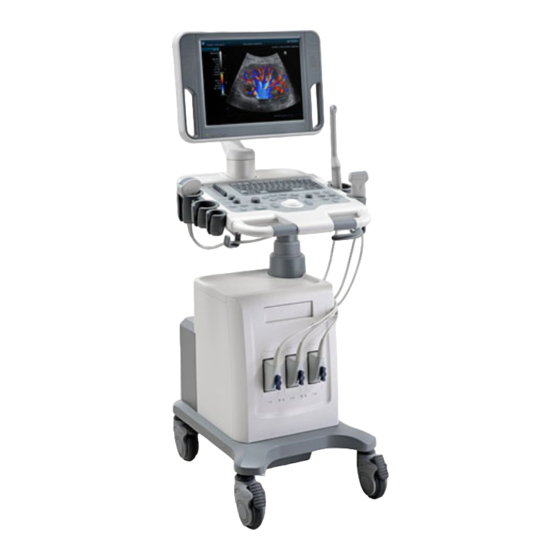
Introduction of Each Unit Name Function Displays the image and parameters during scanning (tilt <1> LCD Display angle adjustable). <2> Control Panel Refer to the 2.6.3 Control Panel. <3> Support arm Used to support the control panel and the display (option). Probe and gel Used to place the probe or gel. -
Page 33: I/O Panel
2.6.1 I/O Panel Symbol Function <1>. USB ports. <2>. Separate video output, connecting video printer. <3>. Composite video signal output, connecting video printer. <4>. Remote control port. <5>. Audio output (left channel). <6>. Audio output (right channel). VGA signal output. <7>. -
Page 34: Power Supply Panel
2.6.2 Power Supply Panel <2> <3> <1> Name Function Used for equipotential connection, that balances the protective Equipotential <1>. earth potentials between the system and other electrical terminal equipment. Auxiliary power output, used to supply power for optional <2>. Power outlet peripheral devices. -
Page 35: Control Panel
2.6.3 Control Panel Name Description Function Off: when system is turned off; <1>. Power button Green: when system is turned on by pressing this button. Indicator Battery status indicator Charging: light in orange Full: light in green Discharge (capacity >20%): light in green <2>. - Page 36 Name Description Function HDD status indicator Read/ write: blinking in green Other status: light off <5>. Indicator NOTE: DO NOT move the machine when the indicator is blinking in green. Otherwise the HDD may be damaged by sudden shake. Exit Press to exit the current status to the previous <6>.
- Page 37 Name Description Function Multifunctional Adjusts the image parameter combed with the key <30>. / Knob of Scale/Baseline/Menu. <31>. Cursor Press to show the cursor. <32>. PW Press to enter PW mode. <33>. Color Press to enter Color mode. <34>. M Press to enter M mode.
-
Page 38: Symbols
Symbols This system uses the symbols listed in the following table, and their meanings are explained as well. Symbol Description Type-BF applied part General warning, caution, risk of danger Dangerous voltage Equipotentiality Power button Network port USB ports Video output Remote control port VGA signal output AC (Alternating current) -
Page 39: System Preparation
System Preparation Move/Posit the System Please read and understand the safety precautions before placing the system to ensure safety for both operator and devices. 1. Switch off the power, and pull out the plug. 2. Disconnect the system from all peripherals. 3. - Page 40 Retaining clamp Power plug Receptacle 2. Push the retaining clamp downward, and lock the power cord, as shown in the figure below. 3. Plug the other end power plug into an appropriate power socket. The grounding terminal should be connected with a power grounding cable to ensure that protective grounding works normally.
-
Page 41: Equipotential Terminal
2. Be sure to connect this system and its peripheral devices to wall receptacles, which meet the rated power requirement written on the nameplate. If adapters or multifunctional receptacles are used, it may cause the leakage current to exceed the safety requirement. In addition, please connect the video printer to the special auxiliary power outlet of this system, and use the cable provided with this system to connect the printer. -
Page 42: Powering On/ Off
Powering ON/ OFF 3.3.1 Powering ON To ensure safe and effective system operation, you must CAUTION: perform daily maintenance and checks. If the system begins to function improperly – immediately stop scanning. If the system continues to function improperly – fully shut down the system and contact Mindray Customer Service Department or sales representative. - Page 43 Checking after it is turned on Press the power button in the upper right corner on the control panel. To check the system after the system is turned on: Check Item <1> There shall be no unusual sounds or smells indicating possible overheating. <2>...
-
Page 44: Powering Off
3.3.2 Powering OFF You need to follow the correct procedures to power off the system. In addition, after you upgrade the software or when the system is down, you need to power off and restart it. If you will not use the system for a long period of time, after powering off the system, you shall disconnect the external power supply;... -
Page 45: Brightness And Contrast
3.4.3 Brightness and Contrast Adjusting the monitor’s brightness and contrast is one of the most important factors for proper image qualities, if these controls are set incorrectly, the gain, TGC, dynamic range or even acoustic output have to be changed more often than necessary to compensate. The adjusting buttons are shown as follows: Brightness: <1>, <2>... -
Page 46: Disconnecting A Probe
Lock NOTE: Before inserting the connector into the probe port, inspect the connector pin. If the pin is bent, don’t use the probe until it has been inspected/repaired or replaced. 3.5.2 Disconnecting a Probe 1. Turn the lock handle 90°counterclockwise to the horizontal position (Shown in the left figure). -
Page 47: Graph / Text Printer
Graph / Text Printer 3.8.1 Connecting a Local Printer As shown in the figure below, a graph / text printer has a power cord and data cable. The power cord shall be directly connected to a wall receptacle as required. Power cord Data cord USB port... - Page 48 Select the printer model from the drop-down list right to the “Printer”; Set “Paper Size”. 6. Click [Save] to finish the installation. Tips: Drivers of some popular printers have already been integrated in the system, and will be installed automatically. You need to check the following information to check if the auto- installation fails: Model of the connected printer is not displayed in the “Printer Driver”...
-
Page 49: Add Network Printer
3.8.2 Add Network Printer 1. Make sure the target network printer and the ultrasound system are both connected into the same LAN. 2. Check the IP address of the network printer (for details, please refer to the accompanying documents of the printer). 3. -
Page 50: Istorage Ultraassist Print
3.8.4 iStorage UltraAssist Print The system supports printing by iStorage function. Before using this function, please make sure that the iStorage server has configured a defaulted printer, and the ultrasound system has configured an iStorage server. For details, please refer to “11.5 Network Preset” chapter. 1. -
Page 51: Analog Video Printer
a) Select an existed printer service in the list. b) Select the printer type in the Property box. c) Set the attribute: paper size. d) Click [Save] to confirm. Image print Select the image to be printed on the iStation or Review screen, and click beside the image or [Send To] to select the printer to print. -
Page 52: Basic Screen And Operation
3.11 Basic Screen and Operation 3.11.1 Basic Screen The following diagram maps out the different areas in the screen: Hospital name Accession# Patient Logo Freeze Information Operator icon Exam time Probe Acoustic power, MI/TI Product Mode Exam Mode Menu area Image Parameters Image area Thumbnail... - Page 53 The freeze icon means the image is frozen. Patient Information Displays patient name, ID, gender and age etc. Press <Patient> on the control panel to enter patient information. Or, import the saved patient data from iStation or the DICOM Worklist server. Probe model Display the currently-used probe model, or the default model.
- Page 54 Parameter area Displays the image parameters for the activating window. If there are more than one imaging modes, the parameters are displayed by each mode. For detailed parameters displayed in this area, please refer to the corresponding imaging mode chapter. Image area The image area displays the ultrasound images, probe mark (or activating window mark), time line (in M mode), coordinate axis (including depth, time, velocity/frequency), focus...
-
Page 55: Basic Operations Of Screens
3.11.2 Basic Operations of Screens Title Contents Control button Composition Description The title bar is used to give a description for the content and function Title Bar of the screen. Use the selection pointer and <Set> key to open / close the available Page Tab pages. -
Page 57: Exam Preparation
Exam Preparation Before examining a new patient, press <End Exam> to end the CAUTION: exam of the previous patient, update the patient ID and information, to avoid mixing data of the next new patient. Start an Exam You can start a patient exam in the following situations: New patient information: to start a new patient exam, enter the patient information first, for details, please refer to “4.2.1 New Patient Information”;... - Page 58 Place the cursor onto the targeted box. The field box is highlighted and a flashing cursor appears. Information can be entered or selected from the options. You can also change the cursor position by <Tab>, <Enter> or up/down controls. Information includes: 1.
- Page 59 age is less than one year, the system will automatically calculate the age in months or days. Also, you can manually enter the age. NOTE: When you enter the date manually, please enter it in the format as that of the system.
- Page 60 Exam Type Information Description Para Times of delivery Aborta Times of abortion Last menstrual period Gravida Times of pregnancy. Para Times of delivery (Gynecology) Ectopic Times of abnormal pregnancy. e.g. extrauterine pregnancy Aborta Times of abortion Height Weight BSA (body After the height and weight are inputted, the system will surface automatically calculate the BSA based on the formula...
-
Page 61: Retrieve Patient Information
[Cancel]: click to cancel the patient data entered and exit the screen. 4.2.2 Retrieve Patient Information 4.2.2.1 iStation The patient data can be obtained in iStation from the system hardware or USB memory device. You can enter the searching conditions for the patient. 1. - Page 62 Button Function Description Review Click to enter the Review screen. Image Patient Click to enter the Patient Info screen. Info Review Click to enter the Diagnostic Report screen. Report Delete Click to delete the selected record. Exam Backup Click to export the selected patient data to media supported. Exam Restore Click to import the patient data from an external media.
-
Page 63: Select Exam Mode And Probe
To reset the criteria, click [Clear] button on the screen. 3. Select the desired patient from the list. Click [Start Exam], the patient information is imported into the system and then an exam is started. Click [Transfer], the patient information is imported into the Patient Info screen. Edit the patient information in the Patient Info screen, and select [OK] to start a new exam. -
Page 64: Selecting Imaging Mode
To save the image parameters for the current exam mode quickly: Click [QSave] to save the image parameters in the current image mode as presets. A dialogue box pops up to prompt you the operation will cover the current image preset data. Click [Exam Preset] to enter the exam preset screen. -
Page 65: End An Exam
4.6.2 End an Exam Before examining a new patient, press <End Exam> on the control panel to end the exam of the previous patient, update the patient ID and information, to avoid mixing data of the next new patient. To end an exam, you can do one of the following: Press <End Exam>... -
Page 67: Image Optimization
Image Optimization The images displayed in this system are only reference for WARNING: diagnosis. Mindray is not responsible for the correctness of diagnostic results. It is the responsibility of the clinician, who performs the exam, to capture the correct diagnostic results. -
Page 68: Basic Operations
Basic Operations Before optimizing the image by adjusting image parameters, adjust the brightness and contrast of the display to the best. Requirement Available Operations Adjust gain Adjust TGC To modify the brightness Adjust [A. power] (do try to adjust gain first before increasing the acoustic power) Adjust [Dynamic Range] Adjust [Gray Map]... - Page 69 Navigating Selecting Selecting parameters (white parameter (blue parameter Finish adjustment shading fonts) level shading fonts) Under Color/Power/PW mode, press <Scale>/<Baseline>/<Menu> on the control panel to switch the adjusting status of the Multifunctional Knob (corresponding key backlight is on). Under non-Smart 3D mode, press <Cursor> on the control panel to show the cursor and use the trackball to move the cursor onto the image parameter menu.
-
Page 70: Quickly Saving Image Setting (Qsave)
Adjusting through control panel: Trackball, control panel key, knob or sliders. Quickly Saving Image Setting (QSave) To enter image parameter saving screen: Press <Probe> and click [QSave], or; Press the user-defined key for QSave function (for details about user-defined key setting, please refer to “11.1.6 Key Config”... -
Page 71: B Mode
B Mode B mode is the basic imaging mode that displays real-time images of anatomical tissues and organs. 5.4.1 B Mode Exam Protocol 1. Enter the patient information, and select the appropriate probe and exam mode. 2. Press <B> on the control panel to enter B mode. 3. - Page 72 Operation To increase the gain compensation at an area of interest, move the TGC slider to the right. To decrease the gain compensation at the corresponding area of interest, move the TGC slider to the left. About 1.5s after the adjustment is finished, the TGC curve disappears. Effects Adjust the signal gain for the certain image area to get a balanced image.
- Page 73 FOV (Field 1. To change the scan range, click [FOV] on the image menu to enter the of View) FOV range and FOV position adjustment status. 2. Press <Set> to switch between adjusting FOV position and FOV range by the icon hint information below the image: indicates FOV position adjusting status, and indicates FOV range adjusting status.
- Page 74 Persistence Description This function is used to superimpose and average adjacent B images, so as to optimize the image and remove noises. Operation Adjust through the [Persistence] item on the menu; The system provides 7 level of frame average adjustment, the bigger the value the stronger the effect.
- Page 75 Tint Map Description Colorize function provides an imaging process based on color difference rather than gray distinction. Operation Select the colorize map through the [Tint Map] item on the menu; The system provides 16 colorize maps to be selected among. Impacts The function is available in real-time imaging, freeze or cine review status.
-
Page 76: M Mode
M Mode 5.5.1 M Mode Exam Protocol 1. Select a high-quality image during B mode scanning, and adjust to place the area of interest in the center of the B mode image. 2. Press <M> on the control panel, and roll the trackball to adjust the sampling line. 3. - Page 77 Effects Adjust according to the actual situation and obtain a desired analysis through comparison. Speed Description This function is used to set the scanning speed of M mode imaging, and the real-time speed value is displayed in the image parameter area in the upper left corner of the screen.
-
Page 78: Color Mode Image Optimization
M Soften Description This feature is used to process the scan lines of M images to reject noise, making the image details to be clearer. Operation Adjust through the [M Soften] item on the menu; The system provides 14 levels of M Soften adjustment, the bigger the value the stronger the effect. - Page 79 Color Gain Description Refers to the overall sensitivity to flow signals, and this function is used to adjust the gain in Color mode. The real-time gain value is displayed in the image parameter area in the upper right corner of the screen. Operations Rotate the <Gain/iTouch>...
- Page 80 Operations Turn on or off the function through the [Invert] item on the image menu. Select “Auto Invert” in the “[Setup] → [System Preset] → [Image]”, then the color bar can automatically invert when the color flow is steered to a certain angle to accommodate operator’s habit of distinguishing flow direction.
- Page 81 B/C Align Description To set and constrain the maximum width of the B mode image to that of the Color ROI. Operations Turn on or off the function through the [B/C Align] item on the image menu. Impacts Frame rate increases when the function is turned on. Dual Live Description This function is used to display B image and Color image synchronously.
-
Page 82: Power Mode Image Optimization
Power Mode Image Optimization Power mode provides a non-directional display of blood flow in the form of intensity as opposed to flow velocity. DirPower (Directional Power mode) provides additional information of flow direction towards or away from the probe. NOTE: Power imaging is an option. -
Page 83: Pw Doppler Mode
Power Map Description This feature indicates the display effect of Power image. The maps in the Power mode image are grouped into two categories: Power maps and Directional Power maps. Operations To select among the maps, turn the knob under [Map] on the image menu. There are 8 kinds of maps provided: P0-3 belong to Power mode maps, while Dp0-3 belong to Directional Power mode maps. -
Page 84: Pw Mode Image Parameters
4. Press <PW> again or <Update> to enter PW mode and perform the examination. You can also adjust the SV size, angle and depth in real-time scanning. 5. Adjust the image parameters during PW mode scanning to obtain optimized image. 6. - Page 85 Operations Adjust through the <Steer> key on control panel or [Steer] item on image menu. Effects This feature is used to steer the direction of the beam so as to change the angle between the beam and flow direction with immobility of the linear probe. Values of steer angles vary by probe.
- Page 86 Operations Adjust through the [Dynamic Range] item on the image menu. The adjusting range is 24-72dB in increments of 2dB. Effects The more the dynamic range, the more specific the information, and the lower the contrast with more noise. HPRF Description HPRF mode is used when detected velocities exceed the processing capabilities of the currently selected PW Doppler scale, or when the selected...
- Page 87 Operations Click the [Gray Map] item on the image menu. There are 8 maps available. Duplex/ Triplex Description This function is used to set if B image (B + Color image) and PW image are displayed synchronously. Operations Click [Duplex/ Triplex] on the image menu to turn on or off the synchronization. Auto Calculation Description This function is used to trace the spectrum and calculate parameters of PW...
-
Page 88: Iscape
Angle Description This function is used to adjust the angle between Doppler vector and flow to make the velocity more accurate. The real-time adjusting angle value is displayed on the right part of the spectrum map. Operations Click the <Angle> item on the image menu to adjust. The adjustable angle range is -89~89°, in increments of 1°. -
Page 89: Image Acquisition
3. Optimize the B mode image: In the acquisition preparation status, click the menu title to enter the B mode image optimization. Do measurement or add comment/body mark to the image if necessary. 4. Image acquisition: Click [Start Capture] or press <Update> on the control panel to begin the acquisition. For details, please refer to “5.9.2 Image Acquisition”. -
Page 90: Iscape Viewing
5.9.3 iScape Viewing After completing the image acquisition, the system performs image splicing and then enters the iScape viewing mode. In iScape viewing mode, you can perform the following functions: Image parameters setting, for details, please refer to “5.9.3.1 Image Parameters ”. Image zooming, for details, please refer to “5.9.3.2 Image Zooming”. -
Page 91: Cine Review
NOTE: iScape panoramic imaging is intended for well-trained ultrasound operators or physicians. The operator must recognize image artifacts that will produce a sub- optimal or unreliable image. The following artifacts may produce a sub-optimal image. If the image quality cannot meet the following criteria, you shall delete the image and do image acquisition again. -
Page 92: Smart 3D
5.10 Smart 3D NOTE: 1. Smart 3D is an option. 2. Smart 3D imaging is largely environment-dependent, so the images obtained are provided for reference only, not for confirming a diagnosis. Please compare the images with that of other machines, or make diagnosis using none- ultrasound methods. -
Page 93: Overview
Scanning technique Stability: body, arm and wrist must move smoothly, otherwise the restructured 3D image distorts. Slowness: move or rotate the probe slowly. Evenness: move or rotate the probe at a steady speed or rate. NOTE: 1. A region with qualified image in B mode may not be optimal for Smart 3D imaging. - Page 94 image Cut plane ROI size and position Roll the trackball to change the ROI size and position, press the <Set> key to toggle between setting the size (dotted line) and position (solid line, with a small box at each corner of ROI). Curved VOI adjustment Roll the trackball to change the curved VOI position, press <Set>...
- Page 95 View Direction a. Up/Down b. Down/Up c. Left/Right d. Right/Left e. Front/Back f. Back/Front Wire cage When you view a Smart 3D image on the display monitor, it’s sometimes difficult to recognize the orientation. To help, the system displays a three-dimensional drawing to illustrate the orientation.
-
Page 96: Basic Procedures For Smart 3D Imaging
Wire Cage The ultrasound images are provided for reference only, not for CAUTION: confirming a diagnosis. Please use caution to avoid misdiagnosis. 5.10.3 Basic Procedures for Smart 3D Imaging NOTE: In Smart 3D image scanning, if the probe orientation mark is oriented to the operator’s finger, please perform the scanning from right to left in linear scan;... -
Page 97: Smart 3D Acquisition Preparation
NOTE: To define a ROI, please try to cut the useless data as to reduce the volume data, shortening the time for image storing, processing and rendering. 5. Select [Render] mode, [Method] (including the distance or angle to be scanned) if necessary. - Page 98 Fan scanning Rotate the probe once from the left to the right side (or from the right to the left) to involve the whole region desired. See the following figure. Parameters description: Type Parameter Description Function: select the image acquisition method. Selection: Fan, Linear.
-
Page 99: Smart 3D Image Viewing
Type Parameter Description Function: set Max as 3D image rendering mode, displays the maximum intensity of gray values in the ROI. This is helpful for viewing bony structures. Function: set Min as 3D image rendering mode, displays the minimum number of gray values in the ROI. This is helpful for viewing vessels and hollow structures. - Page 100 Select [Cur. Win] to be the desired window, then the current active window will be highlighted by different colors of frame. A, B, C sectional images (MPR) are corresponding to the following sections of 3D image. Section A: corresponds to the 2D image in B mode. Section A is the sagittal section in fetal face up posture, as shown in the figure A above.
- Page 101 Parameter Description Function: set Surface as 3D image rendering mode. This is helpful for surface imaging, such as fetus Surface face/hand or foot. Tips: you may have to adjust the threshold to obtain a clear body boundary. Function: set Max as 3D image rendering mode, displays the maximum intensity of gray values in the ROI.
- Page 102 Display Format Image display format: click [Format] on the menu to set the image display format,. Here, Select [Single], system displays one image, which can be a sectional image (MPR) or a 3D image (VR). Select [Dual], system displays two images left and right. Select [Quad], system displays four images.
- Page 103 Rotating the Image The system supports the following rotation modes: Sphere center rotation Axial rotation Auto rotation Quick rotation Sphere center rotation Rotate the 3D image around the center point of the 3D image. Procedures a) Set 3D image window as the current window. Click [Cur.
- Page 104 NOTE: You can view the back of the 3D image by rotating it 180°, but the back view image may not as vivid as the front. (Here we call the initial view of the 3D image you see as “front”). It’s recommended to re-capture than to rotate the 3D image remarkably if a certain region desired is blocked in the 3D image.
-
Page 105: Image Saving And Reviewing In Smart 3D
Type Parameters Description Allows you to trace the portion of the image you want to cut. Inside Contour Inside Contour removes all portions of the image that fall inside your traced region. Allows you to trace the portion of the image you want to cut. Outside Contour Outside Contour removes all portions of the image that fall outside your traced region. -
Page 107: Display & Cine Review
Display & Cine Review Image Display 6.1.1 Splitting Display The system supports dual-split and quad-split display format. However, only one window is active. Dual-split: press <Dual> key on the control panel to enter the dual-split mode, and using <Dual> key to switch between the two images; press <B> on the control panel to exit. -
Page 108: Freeze/ Unfreeze The Image
3. Exit: Press <Depth/Zoom>. Unfreeze the image, the system exit pan zooming status automatically. 6.1.2.3 iZoom (Full-screen Zooming) Function: to magnify the image in full screen. According to the region to be zoomed, the system supports two types of full-screen zooming: Zoom in the standard area to full-screen, including image area, parameter area, image banner, thumbnail area and so on. -
Page 109: Cine Review
2D+PW (Press <Freeze> in 2D+PW scanning mode) If the imaging mode before frozen is 2D (frozen) +PW (real time) or 2D (real time) +PW (frozen), then in freeze mode, you can switch between 2D(real time)+PW(frozen) or 2D(frozen)+PW(real time)) by pressing <Update> key on the control panel. Dual/quad splitting display mode (Press <Freeze>... -
Page 110: Cine Review In M/ Pw Mode
Manual Cine Review: After entering the cine review of 2D mode, roll the trackball to review the cine images on the screen one by one. If you roll the trackball to the left, the review sequence is reversed to the image-storing sequence, thus the images are displayed in descending order. -
Page 111: Linked Cine Review
Roll the trackball to the left, the review progress slider moves to the left, the images moves to the right, and the earlier stored images are invoked. Whereas roll the trackball to the right, the review progress slider moves to the right, and the images move to the left, the recently stored images are invoked. -
Page 112: Frame Compare
4. Review the images of different image windows (cine replaying can’t be performed for single-frame image file), press <Dual> or user-defined Quad key to switch the active image window. The window with the highlighted “M” mark is the current activated window. Press <Cursor>... -
Page 113: Cine Memory
Cine Memory 6.4.1 Cine Memory Setting There are 2 ways of cine memory split: auto and split. Setting path: select "Auto" or "Split" for cine memory in [Preset]→ [System Preset]→ [Image]. Where, "Auto" for the cine memory indicates the system splits the cine memory as per the number of B image windows. -
Page 114: Preset
Preset Open [Setup] ->[System Preset]->[General] to preset the cine storage length. Clip length: 1~60s. 6-8 Display & Cine Review... -
Page 115: Measurement
Measurement There are general measurement and application measurement. You can perform measurements on a zoomed image, cine reviewing image, real-time image, or a frozen image. For measurements details, please refer to the [Advanced Volume]. Be sure to measure areas of interest from the most optimal WARNING: image plane... -
Page 116: M General Measurements
Measurement Tools Function Volume The volume of a target. Measures the length of two line segments, which are perpendicular to Double Dist each other. Parallel The distance between each pair of parallel lines in a sequence. Trace Length Measures the length of a curve on the image. Measures the lengths of any two line segments and the calculated Distance Ratio ratio. -
Page 117: Application Measurement
Measurement Function Tools Velocity and PG between two peaks on the Doppler spectrum to PS/ED calculate RI (resistance index) and PS/ED (peak systolic/end diastolic). Volume Flow Blood flow through some vascular cross section per unit time. Application Measurement The system support following measurement types: Abdomen measurements - Used for measurements of abdominal organs (liver, gall bladder, pancreas and kidney, etc.) and large abdominal vessels. -
Page 118: Measurement Accuracy
Measurement Accuracy Table 1 Error of 2D Images Parameter Value Range Error Distance Full screen Within ±4% Area Full screen Within ±8% Circumference Within ±20% Angle Full screen Within ±3%. Linear and convex-wide probe: within ±10% Distance (iScape) Full screen Micr-convex probe: within ±15% Table 2 Volume Measurements Parameter... -
Page 119: Comments And Body Marks
Comments and Body Marks Comments Comments can be added to an ultrasound image to bring attention, notate or communicate information observed during the examination. You can add comments to: zoomed image, cine review image, real-time image, frozen image. You can type the character as comments; insert the pre-defined comments from the comment library;... - Page 120 Home of comments Assign the user-defined key for the set home function in “[Setup] → [System Preset] → [Key Config]”. Move the cursor to the desired location for a comment and click the Set-Home user- defined key. The current position of the cursor is set to be the default position of the comment adding.
-
Page 121: Adding Comments
1. Use the trackball and <Set> to click to navigate the comment items; 2. Move the cursor onto the target comment and press <Set>. 3. Use the keyboard to type in the letters. 8.1.3 Adding Comments Typing comment characters 1. To set the comment location: Roll the trackball or press direction-control keys on the keyboard to move the cursor to the desired location for comments. -
Page 122: Moving Comments
Adding an Arrow You can add an arrow to a location where you want to pay attention. Press the <Arrow> key, and an arrow will appear at the default position. Adjust the arrow Adjust the position and orientation of the arrow: roll the trackball to the desired position and use the Multifunctional Knob to change the orientation in 15°... -
Page 123: Body Mark
NOTE: When no object is selected, pressing the <Clear> key will clear all comments and all measurements calipers. After powering off, the system will clear all comments on the image. Body Mark The Body Mark (Pictogram) feature is used for indicating the exam position of the patient and transducer position and orientation. -
Page 124: Deleting Body Marks
3. Roll the trackball to move the Body Mark graphic to the desired position. 4. Press <Set> to anchor and confirm the new graphics position. NOTE: In Dual B Mode, a body mark cannot be moved between the separated image windows. -
Page 125: Patient Data Management
Patient Data Management An exam record consists of all information and data of one exam. An exam record consists of the following information: Patient basic information and exam data Image files Report NOTE: DO NOT use the internal hard drive for long-term image storage. Daily backup is recommended. -
Page 126: Image Storage Preset
The system can save FRM files as BMP, JPG, TIFF or DCM files, or save CIN files as AVI, DCM files. The system can also open FRM, JPG, BMP and CIN files. PC-compatible formats: Screen file (BMP) Single-frame file format, used to save the current screen, non-compressed format; Screen file (JPG) Single-frame file format, used to save the current screen in the compressed format;... -
Page 127: Quickly Saving Images To Usb Flash Drive
The thumbnail of this image will appear in the thumbnail area on the lower side of the screen. When you move the cursor onto the thumbnail, its filename with suffix will be displayed. 9.2.5 Quickly Saving Images to USB Flash Drive Use user-defined keys to quickly save the single-frame or cine to USB flash drive. - Page 128 To enter Review: Press <Review> on the control panel to enter Review screen. The system display the images stored in this exam of the current patient (if there is no current patient information, you can review the images of the latest exam). Select an exam of a patient in the iStation screen, and click to enter the Review screen to review the images of the patient.
-
Page 129: Ivision
Click to enter the Patient Info screen, you can review or edit the currently-selected patient information. Report Click to review or edit the currently-selected patient report. Image operations [Select All]: click to select all images in the thumbnail window. [Deselect All]: after clicking the [Select All], the button changes into [Deselect All], you can cancel all the selections by clicking [Deselect All]. - Page 130 3. Select an item in the list, and click [Start] to begin the demonstration. 4. Click [Exit] or press <ESC> to exit the iVision status. The iVision screen is shown as follows: Demonstration item The demonstration items are the image files in the formats that the system supports. You can add the exam data in patient database or system supported image files and folders to demonstration list.
-
Page 131: Sending Image File
Demonstration mode Interval: refer to the interval time for demonstration, the adjusting range is 1~500s. Option of Demo You can choose whether to repeat the demonstration or exit after a demonstration is completed. 9.2.10 Sending Image File On the image screen, select a stored image thumbnail, click the Send To Arrow on the right corner of the image, the image can be sent to the external device, DVD recorder, DICOM storage server, DICOM print server, system connected printer and etc. -
Page 132: Patient Data Management (Istation)
Importing, exporting and sending a report In the iStation screen, select patient data, click (Restore) or (Backup) to import or export patient information, images and reports from or to an external memory device. See the following figure: In the iStation screen, click the Send To Arrow; or, in Review screen, click [Send To] to send patient data to an external memory device, you can choose if reports are exported with images. -
Page 133: Searching A Patient
Data Source Select the data source of patient data, the system patient database is default. Patient List Display patient information, exam mode, number of images and cines, exam state, backed up or not. New Exam After you select a patient data or exam in the iStation screen, click the [New Exam] to enter the Patient Info screen, where you can select a new exam mode and click [OK] to begin a new exam. -
Page 134: Patient Data View & Management
9.4.2 Patient Data View & Management Select the desired patient information in the list. The following menu pops up: Review Select an exam of a patient, click to enter Review screen. Info Select an exam of a patient, click on the right side to display the patient information of this exam. - Page 135 Press <Shift> on the control panel to select more than one exam or image at one time. Activate exam After you select an exam, which has been performed within 24 hours, click activate the exam and load the basic patient information and measurement data to continue the exam.
-
Page 136: Backing Up And Erasing Files Through Dvd Drive
Backing Up and Erasing Files through DVD Drive The system supports DVD-RW to write data in CD/DVD and to read data from CD/DVD in PC. Support media: DVD±RW, CD-R/W. NOTE: DVD R/W Drive is an option. To write data to a CD/DVD: (1) Put a CD/DVD in the tray. -
Page 137: Patient Task Manager
Patient Task Manager Click at the lower right corner of the screen to pop up the following dialogue box: Including: Storage Task: displays the DICOM storage task. DICOM Print Task: displays the DICOM print task. Media Storage Task: DICOM media storage task(including disc and USB devices) Backup task (system-relevant format): select the exam to be backed up in iStation and click Send to external devices (including disc and USB devices): select exam data or... -
Page 138: Access Control
Retry Click [Retry] to retry the failed task. When the printer ran out of ink or paper, tasks in print list will be paused. Click [Retry] to continue the paused print task. Select All Click [Select All] to select all the tasks. Task Status Select the undergoing task, the system will display its detailed status information or error information. -
Page 139: Add/ Delete A User
Changing user As long as the system is in working status, you can enter the above screens without inputting user name and password repeatedly. You need to login again after system restart or dormancy. Login the system: (1) If the system requires you to log on the system before you access the data, you can see the following dialogue box. - Page 140 2. Click [Add] to enter the following page. 3. Enter the user name (you are not allowed to enter the same name or modify the name already exist). 4. Enter user name and the password. 5. Set the user role in the drop-down list: administrator or operator. 6.
-
Page 141: Modify Password
9.7.5 Modify Password The system administrator can modify password of all users. The administrator password by factory is empty, you can set the password for it. The operator can only modify his/her own password. To modify the password, the user has to login the system first. There are two ways to modify password: modify it on “Admin”... -
Page 143: Dicom
DICOM NOTE: Before using DICOM, please read the electronic file DICOM CONFORMANCE STATEMENT along with the device. This chapter is confined to the preset, connection verification and DICOM services of the DICOM-configured ultrasound machine, not including SCP configurations like PACS/ RIS/ HIS. NOTE: DICOM functions are optional. -
Page 144: Dicom Preset
10.1 DICOM Preset 10.1.1 Network Preset Preset local TCP/IP settings. 1. Press <Setup> to enter the [Setup] menu. 2. Select [Network Preset]. 3. Local TCP/ IP preset items are described as follows: Name Description Current Net Adapter To select network connection mode. DHCP DHCP: IP address will be automatically obtained from DNS server;... -
Page 145: Dicom Preset
10.1.2 DICOM Preset To set the DICOM service and server properties. 1. Press <Setup> to enter the [Setup] menu. 2. Select [DICOM Preset]. 3. Preset local DICOM properties and DICOM server. Localhost DICOM Service Property Name Description Application entity title of the ultrasound system. AE Title The AE title here should be the same with the one of the acceptable SCU set in the server. - Page 146 DICOM Server Setting Name Description Device Name of the device supporting DICOM services. IP Address IP address of the server. You can ping other machines to verify connection after entering the Ping correct IP address. Also you can check the connection of the already added server in the list.
- Page 147 DICOM storage setting items are described as follows: Name Description After you set the server (s) in DICOM Server Setting, the name Device (s) will appear in the drop-down list, select the name of the storage server. Service Name Default is xxx-Storage, and it can be modified. Application Entity title, Here, it should be consistent with that of AE Title the storage server.
- Page 148 Name Description Select an item in the service list, change the parameters in the [Update] above area, and click [Update] to update the item in the service list. [Delete] Click to delete the selected service in the service list Select an item in the service list, click [Default] and you can see [Default] “Y”...
- Page 149 DICOM print setting items are described as follows: Name Description After you set the server (s) in DICOM Server Setting, the name (s) Device will appear in the drop-down list, select the name of the print server. Service Name Default is xxx-Print, and it can be modified. Application Entity title.
- Page 150 Name Description [Delete] Click to delete the selected service in the service list. Select an item in the service list, click [Default] and you can see “Y” [Default] in the Default column. Click to verify if the two DICOM application entities are normally [Verify] connected.
-
Page 151: Dicom Service
2. Select device, enter the right AE Title, port, etc. 3. Click [Add] to add the service to the Service List. 4. Click [Exit] to confirm the preset and exit the page. DICOM Query/Retrieve service parameters are similar to those described in DICOM Storage Preset, please refer to “10.1.3.1 Storage”... -
Page 152: Dicom Print
(3) Select DICOM in the “Target” list, select a server in the “Storage Server” list. (4) Click [OK] to start the sending. To send image for storage after an exam ends (1) Open “[Setup] (F10) → [System Preset] → [General]”, and then check in the Patient Management box. -
Page 153: Dicom Worklist
(3) Click [OK] to send print task. To send image for print after an exam ends 1) Open “[Setup] (F10) → [System Preset] → [General]”, and then check in the Patient Management box. 2) Set a default print server. a) Enter the DICOM Service Preset screen via “[Setup] (F10) → [DICOM Preset] → [Set DICOM Service]→... - Page 154 (3) Retrieve Patient Information a) Set query criteria among Patient ID, Patient Name, Accession #, Search Key, Worklist Server or Exam Date. The default exam date is the current date. b) Click [Query]. c) The scheduled patients, which meet the criteria, are displayed in the lower part of the screen.
-
Page 155: Mpps
In the off-line status, you can: Perform a second query; or, Click [Show Detail] to view the patient information in details. 10.3.4 MPPS MPPS is used to send exam state information to the configured server. This will facilitate the other systems to obtain the exam progress in time. The status information is described as below: When you begin an exam or send image(s) during the exam, the system sends status information “Active”... -
Page 156: Query/Retrieve
NOTE: Multi-frame storage is not allowed if “Allow Multiframe” is not selected ([Setup]-> [DICOM Preset] -> [Set DICOM Service] -> [Storage]). For example, if there is multi-frame file in the exam to be sent, then only single-frame image storage will be performed, and after the storage is completed, there is no “√”... -
Page 157: Dicom Media Storage
8. Click [Exit], you can see the retrieved patient records are listed in the iStation screen. 10.4 DICOM Media Storage The system supports to save patient data to the external media in DCM format. Meanwhile, in the system, you can view the saved DCM files from external media Media storage: 1. -
Page 158: Structured Report
2. In iStation, review the data stored in the external media. 3. Select the data to be restored in iStation. 4. Click in the iStation screen. NOTE: Only the system accessible media can be selected. 10.5 Structured Report DICOM OB/GYN Structured report, Cardiac Structured report and Vascular Structured report are supported by this system, they can be sent together with the exam only. -
Page 159: Setup
Setup The Setup function is designed to set the configuration parameters of operating the system and maintaining user workflow setup data. The setup data of the user and system are stored to the hard drive, and should be backed up to CD/DVD or USB memory devices. When the setup data is changed, be sure to save the preferences CAUTION: according to the methods described in this chapter. -
Page 160: Region
11.1.1 Region Open the Region page via [Setup]-> [System Preset]-> [Region]. Item Description To set the hospital relevant information like name, address, telephone Hospital Information and so on. To select a language for the system, the available languages are Chinese, English, French, German, Italian, Portuguese, Russian, Spanish, Polish, Czech, Turkish, Finnish, Danish, Icelandic, Language Norwegian, and Swedish. - Page 161 Type Item Description To select if to display the following patient information Info displays in on the image banner: Gender, Age, Operator, ID, image banner Name, Hospital Patient Info H&W Unit To set the unit for patient height and weight. Surface Formula To set the surface formula.
-
Page 162: Image Preset
Type Item Description Status after exam Select to enter the imaging scanning, patient info or the Exam Setup ends Worklist after ending an exam. Color temperature Cold/ Warm. Display Brightness/Contrast Load the factory data of the display brightness and Load Factory contrast. -
Page 163: Application
Type Item Description The spectrum can automatically invert when the color Auto Invert flow is steered to a certain angle, thus accommodating operator’s habit of distinguishing flow direction. Cine Memory To set the cine memory splitting type. iScape Ruler To set if to display the iScape ruler on iScape imaging Display mode. -
Page 164: Admin
The following introduces an example as setting <F1> as “Save AVI Cine to USB disk”: (1) Select F1 in the “Key Function” list at the left side of the page. (2) Select “Save AVI Cine to USB disk” in “Function” at the right side of the page. (3) Click [Save] to complete the setting. -
Page 165: Measure Preset
1. To select a probe: Move the cursor to [Probe] on the exam preset screen, and select a probe from the drop- down list. 2. Selecting/delete exam modes On the right side of the screen, you can view the exam types supported by the current probe. -
Page 166: Network Preset
Print Service Setting Add Service: click to begin print service adding. Remove Service: click to delete the selected print service. Rename Service: click to rename the selected print service. Property: to preset the property of print services. Printer Driver Setting Printers listed in the operator’s manual are all supported by the system, no drive is required. -
Page 167: Maintenance
Name Description Press to verify connection with the PC server. On PC server, if the storage path has not been confirmed, a dialog box will pop up and Connect guide the user to set it. If the storage path on PC has already been set, here it displays connection successful after clicking this button. -
Page 169: Probes And Biopsy
Probes and Biopsy 12.1 Probe The system supports the following probes: Probe Probe Illustration Illustration Model Model 35C50EA 65C15EA 65EC10EA 35C20EA 65EC10ED 10L24EA 75L38EA 65EB10EA Probes and Biopsy 12-1... -
Page 170: Probe Functions By Part
Probe Probe Illustration Illustration Model Model 35C50EB 75L38EB 65EC10EB 75L53EA NOTE: For details of storage time and condition for disinfected probes or sterilized probes and brackets, please refer to Technical standard for Disinfection of Medical and Health Structures 12.1.1 Probe Functions by Part Basic structures and functions of all probes listed above are similar, and are described as follows. -
Page 171: Orientation Of The Ultrasound Image And The Transducer Head
Name Function Converts the electrical signal into an ultrasonic signal, focusing the sound beams in a given direction; meanwhile, it receives the reflected ultrasonic signal and then converts <1> Transducer head it into an electrical signal for transmission over the cable. The lens on the surface is the acoustic lens. -
Page 172: Operating Procedures
12.1.3 Operating Procedures This section describes general procedures for operating the probe. The proper clinical technique to be used for operating the transducer should be selected on the basis of specialized training and clinical experience. Procedures for operating Inspection before examination Connection to the ultrasonic diagnostic system Examinations... - Page 173 Procedures for operating (with no biopsy function) Inspection before examination Connection to the ultrasonic diagnostic system Examinations Disconnection to the ultrasonic diagnostic system Wiping off the ultrasound gel Washing the transducer with water Draining/drying Disinfection Immersion into disinfectant Removing the transducer from disinfectant Rinsing the transducer into sterile water Draining/drying...
-
Page 174: Wearing The Transducer Sheath
12.1.4 Wearing the Transducer Sheath A transducer sheath must be installed over the transducer before performing examination. Probe sheaths are available for use with all clinical situations where infection is a concern. A probe sheath must be installed over the probe before performing intra-cavity or biopsy examination. -
Page 175: Probes Cleaning And Disinfection
12.1.5 Probes Cleaning and Disinfection After completing each examination, clean and disinfect (or sterilize) the probes as required. When biopsy procedures have been performed, be sure to sterilize the needle-guided bracket. Fail to do so may result in the probe and the needle-guided bracket to becoming sources of infection. - Page 176 Connector Strain relief NOTE: Observe the graph here carefully to perform disinfection. Do not spray the strain relief on the connector end or the connector. Disinfecting by Immersion 1. Wear sterile gloves to prevent infection. 2. Clean the transducer before disinfecting it. MINDRAY recommends the following solutions to disinfect the transducer.
- Page 177 Strain relief Probe handle NOTE: Observe the graph here carefully to immerse the transducer. Only soak parts of the transducer below the strain relief. Repeated disinfection will eventually damage the probe, please check the probe performance periodically. Compatible Disinfectants Manufacturer Trade Name Procedures Type...
-
Page 178: Storage And Transportation
Manufacturer Trade Name Procedures Type Please refer to the instructions Minntech Minncare® Cold provided by the manufacturer of Solution*** Corporation Sterilant the solution for details. “**” denotes if the disinfectant is not applicable for the probe 65EC10ED. “***” denotes if the disinfectant is not applicable for the probe 65EC10ED. 12.1.6 Storage and Transportation When all examinations for the day have been completed, confirm that the transducer is in good condition. -
Page 179: Biopsy Guide
12.2 Biopsy Guide The person performing biopsy procedures must understand diagnostic ultrasound thoroughly and WARNING: have been trained adequately, otherwise, side effects may be produced in the patient. In situations listed below, the biopsy needle may fail to penetrate the target. The incorrect biopsy may cause various side effects to the patient. - Page 180 Adjust the needle mark before the biopsy procedure is performed. When performing biopsy procedures, use only sterile ultrasound gel that is certified to be safe. And manage the ultrasound gel properly to ensure that it does not become a source of infection. When performing the operation concerning biopsy, wear sterile gloves.
-
Page 181: Basic Procedures For Biopsy Guiding
1. When using the needle-guided bracket, wearing sterile gloves CAUTION: can help to prevent infection. 2. During biopsy of the probe 65EB10EA, misoperation may occur when the scan range is not set to “W”, which will affect the blind area of the image and the accuracy of needle displaying. -
Page 182: Needle-Guided Brackets
12.2.2 Needle-guided Brackets A needle-guided bracket is available for purchase as an optional accessory; it is used in combination with this transducer. Part of the probes have matched needle-guided bracket and needles. To order needle-guided brackets, contact MINDRAY Customer Service Department or sales representative. - Page 183 NGB-003 (Metal/needle detachable) Name Description Clamp of needle- Used for installing the needle-guided bracket on the <1> guided bracket transducer Groove of the <2> needle-guided Matches with the tab of the transducer bracket <3> Angle adjusting base There are 3 types of angles available to be adjusted Angle shift sign (11°, <4>...
-
Page 184: Needle-Guided Bracket Inspection And Installation
NGB-016 Name Description Clamp of needle-guided Used for installing the needle-guided bracket on the <1> bracket transducer. Groove of the needle- <2> Matches with the tab of the transducer. guided bracket <3> Angle adjusting base There are 3 types of angles available to be adjusted. Matches with the biopsy angle Angle shift sign (30°, 40°, <4>... - Page 185 Installing the Needle-guided Bracket NGB-001, NGB-002, NGB-003 and NGB-005 metal/needle un-detachable needle-guided bracket (taking NGB-001 as example) (1) Put on the sterile transducer sheath. (2) Inosculate the locating groove on the clamp with the two raised edges on the transducer head and aligning the locating pit of the clamp to the convex point on the transducer head.
- Page 186 (4) Select a proper guiding block and push it into the groove above the angle block. (5) Screw the nut of the block to secure the block. (6) Insert a biopsy needle with the same specification as that of the guiding block into the hole of the guiding block.
-
Page 187: Biopsy Menu
(2) Select a proper needle-guided bracket, and match the groove with the tab of the transducer. Mount the bracket onto the transducer. (3) Screw the pinch nut of the needle-guided bracket to confirm that the needle-guided bracket is properly installed on the transducer. (4) Select a proper guiding block and push it into the groove above the angle block, and clamp it tightly. -
Page 188: Verify Biopsy Guide Line
Select Dot size Move the cursor onto [Dot Size], press <Set> to select the dot size among Small, Medium and Large. Tips: The guide line is a dot line which consists of two kinds of dots, the distance between two dots is depth dependent. Move the cursor onto the big dot, a numeral, which represents the biopsy depth, is displayed. -
Page 189: Removing The Needle-Guided Bracket
Move the cursor onto [Angle], press <Set> key to change the guide line angle, or press and rotate the Multifunctional Knob. This is operative when there is only one guide line displayed. Save verified settings After the position and angle of the guide line are adjusted, click [Save], and the system will save the current settings of the guide line. - Page 190 (2) Separate the residual part of the needle-guide bracket and the transducer from the needle. (3) Screw the pinch nut of the bracket, and remove the needle-guided bracket from the transducer. NGB-004 Hold the transducer in the left hand, unscrew the locking nut with the right hand to open the retaining clamp, and then raise the needle-guided bracket to separate the locating bulge from the locating grooves.
-
Page 191: Clean And Sterilize The Needle-Guided Bracket
12.2.7 Clean and Sterilize the Needle-guided Bracket Cleaning 1. Wear sterile gloves to prevent infection. 2. Or, wash with clean water or soapy water to remove all the foreign matters, or, wipe the bracket with a soft ethyl carbamate sponge. 3. -
Page 192: Storage And Transportation
Refer to the instruction of STERRAD 100S sterilizing system provided by the manufacturer for operation instructions and cautions. The STERRAD 100S low-temperature hydrogen peroxide gas plasma sterilization system is available for metal needle-guided brackets. High-pressure steam sterilization (only applicable for metal guided-bracket) Autoclaving (moist heat) 121 ... -
Page 193: Battery
Battery The battery is inside the machine; only technical WARNING: professionals from Mindray or engineers authorized by Mindray after training can perform battery installation and uninstallation. If you need to change the battery or buy a new one, please contact your sales representative. NOTE: Battery is an option. -
Page 194: One Full Discharge / Charge Cycle
13.4 One Full Discharge / Charge Cycle If the battery has not been used for over 2 months, you are recommended to perform one full discharge / charge cycle. It is also recommended that the battery is stored in the shady and cool area with FCC (full current capacity). -
Page 195: Acoustic Output
Acoustic Output This section of the operator’s manual applies to the overall system including the main unit, transducers, accessories and peripherals. This section contains important safety information for operators of the device, pertaining to acoustic output and how to control patient exposure through use of the ALARA (as low as reasonably achievable) principle. -
Page 196: Mi/Ti Explanation
14.4 MI/TI Explanation 14.4.1 Basic Knowledge of MI and TI The relationship of various ultrasound output parameters (frequency, acoustic pressure and intensity, etc) to bioeffects is not fully understood presently. It is recognized that two fundamental mechanisms may induce bioeffects. One is a thermal bioeffect with tissue absorption of ultrasound, and another one is a mechanical bioeffect based on cavitations. -
Page 197: Acoustic Power Setting
NOTE: If there is a value of MI or TI exceeds 1.0, you must be careful to practice the ALARA principle. The display precision is 0.1. Display accuracy of MI is ±28.5%, TI is±38.7% 14.5 Acoustic Power Setting Acoustic power adjustment Click [A. -
Page 198: Acoustic Output
Indirect Controls The controls that indirectly affect output are many imaging parameters. These are operating modes, frequency, focal point positions, image depth and pulse repetition frequency (PRF). The operating mode determines whether the ultrasound beam is scanning or non-scanning. Thermal bioeffect is closely connected to M mode. Acoustic attenuation of tissue is directly related to transducer frequency. -
Page 199: Differences Between Actual And Displayed Mi And Ti
14.7.3 Differences between Actual and Displayed MI and In operation, the system will display to the operator the Acoustic Output Parameters Thermal Index, TI, or Mechanical Index, MI (or sometimes both parameters simultaneously). These parameters were developed as general indicators of risk from either thermal or mechanical action of the ultrasound wave. -
Page 200: References For Acoustic Power And Safety
14.9 References for Acoustic Power and Safety “Bioeffects and Safety of Diagnostic Ultrasound” issued by AIUM in 1993 “Medical Ultrasound Safety” issued by AIUM in 1994 "Acoustic Output Measurement Standard for Diagnostic Ultrasound Equipment, Revision 3" issued by AIUM/NEMA in 2004 "Standard for real-time display of thermal and mechanical acoustic output indices on diagnostic ultrasound equipment, Revision 2"... -
Page 201: Guidance And Manufacturer's Declaration
Guidance and Manufacturer’s Declaration The system complies with the EMC standard IEC60601-1-2: 2007. The use of unapproved accessories may diminish system WARNING: performance. NOTE: 1 Use of accessories, transducers, and cables other than those specified may result in increased emission or decreased immunity of system. 2 The system or its components should not be used adjacent to or stacked with other equipment. - Page 202 TABLE 1 GUIDANCE AND MINDRAY DECLARATION—ELECTROMAGNETIC EMISSIONS The system is intended for use in the electromagnetic environment specified below. The customer or the user of system should assure that it is used in such an environment. ELECTROMAGNETIC ENVIROMENT- EMISSIONS TEST COMPLIANCE GUIDANCE The system uses RF energy only for its...
- Page 203 TABLE 2 GUIDANCE AND MINDRAY DECLARATION—ELECTROMAGNETIC IMMUNITY The system is intended for use in the electromagnetic environment specified below. The customer or the user of system should assure that it is used in such an environment. IEC 60601 COMPLIANCE ELECTROMAGNETIC IMMUNITY TEST LEVEL ENVIRONMENT-GUIDANCE...
- Page 204 TABLE 3 GUIDANCE AND MINDRAY DECLARATION—ELECTROMAGNETIC IMMUNITY The system is intended for use in the electromagnetic environment specified below. The customer or the user of system should assure that it is used in such an environment. IMMUNITY IEC 60601 COMPLIANCE ELECTROMAGNETIC TEST TEST LEVEL...
- Page 205 TABLE 4 RECOMMENDED SEPARATION DISTANCES BETWEEN PORTABLE AND MOBILE RF COMMUNICATION DEVICE AND SYSTEM The system is intended for use in an electromagnetic environment in which radiated RF disturbance are controlled. The customer or the user of system can help prevent electromagnetic interference by maintaining a minimum distance between portable and mobile RF communication equipment (transmitters) and system as recommended below, according to the maximum output power of the communication equipment.
-
Page 207: System Maintenance
System Maintenance Routine system maintenance shall be carried out by the user. System maintenance after the warranty has expired is the full responsibility of the owner/operator. The responsibility for maintenance and management of the product after delivery resides with the customer who has purchased the product. If you have any questions, please contact Mindray Customer Service Department or sales representative. - Page 208 Remained stain or dust attached to surface of transducer cable should be washed out by cloth with clear water or soapy water, and then air-dry the surface of transducer cable; Use a soft brush to clean the transducer holder, removing dust simultaneously. Please refer to the operator’s manual of the corresponding transducer or “12.1.5 Probes Cleaning and Disinfection”...
- Page 209 Rotary ball Clamping ring Top cover b) Cleaning Clean the two long shafts, the bearing and the rotary ball with soft dry cloth or paper. Bearing Long shaft Long shaft c) Installing Put the rotary ball back in the trackball and then align the clamping ring click with the top cover notch.
-
Page 210: Checking The Power Cable And Plug
Cleaning the peripherals Do the cleaning maintenance according to your actual peripheral configuration; items which are not configured can be skipped. Content Description First wipe off dust or stain attached to the cover of printer with soft dry Color and B/W cloth, then clean the inside of printer. - Page 211 Fixing and rotating 1. Visually check to confirm if any inclination happened to the monitor. mechanism of the 2. Manually operate the monitor to make sure the monitor can move monitor normally when it is turned left/ right, lifted/ lowered, and no abnormal sound exists.
-
Page 212: Troubleshooting
16.2 Troubleshooting To ensure proper system operation and function, it is recommended that a maintenance and inspection plan be established to periodically check the safety of the system. If any system malfunction is experienced, contact Mindray Customer Service Department or sales representative. -
Page 213: Appendix A Iscanhelper
Appendix A iScanHelper By providing the referential information, such as, the ultrasonic image, the anatomic graphic, scanning pictures/other scanning tips or diagnosis comments, the system helps the doctors to operate the scanning by iScanHelper. Furthermore, it is a good platform for the self-learning and training of ultrasound scanning technique for doctors. - Page 214 You can zoom in a single window in the help information area to see the information. For details, please refer to “A.4.3 Single/quad-window Display”. 4. Save images as necessary. 5. Press <Help> again to exit iScanHelper. Basic Screen and Operation Section selecting box Image...
- Page 215 Ultrasonic Anatomic image graphic Scanning Scanning picture tips Ultrasonic image It is used to compare with images scanned by the operator. Anatomic graphic Related anatomical tissue information are provided here. Scanning picture Ordinary scanning tips can be observed here, including posture, probe mark, probe swing/sweep techniques.
-
Page 217: Appendix B Electrical Safety Inspection
Appendix B Electrical Safety Inspection The following electrical safety tests are recommended as part of a comprehensive preventive maintenance program. They are a proven means of detecting abnormalities that, if undetected, could prove dangerous to either the patient or the operator. Additional tests may be required according to local regulations. - Page 218 B.2.1 Visual Inspection Test Item Acceptance Criteria No physical damage to the enclosure and accessories. No physical damage to meters, switches, connectors, etc. The enclosure and No residue of fluid spillage (e.g., water, coffee, chemicals, accessories etc.). No loose or missing parts (e.g., knobs, dials, terminals, etc.).
- Page 219 LIMITS For UL60601-1, 300 μA in Normal Condition 1000 μA in Single Fault Condition For IEC60601-1, 500 μA in Normal Condition 1000 μA in Single Fault Condition Enclosure Leakage Test The following outlet conditions apply when performing the Enclosure Leakage test. normal polarity (Normal Condition);...
- Page 220 100 μA in Normal Condition 500 μA in Single Fault Condition Mains on Applied Part Leakage The Mains on Applied Part test applies a test voltage, which is 110% of the mains voltage, through a limiting resistance, to selected applied part terminals. Current measurements are then taken between the selected applied part and earth.
- Page 221 P/N: 046-005132-00 (V4.0)
Need help?
Do you have a question about the DC-N2 and is the answer not in the manual?
Questions and answers