
Related Manuals for Sutter Instrument MP-225


Summary of Contents for Sutter Instrument MP-225
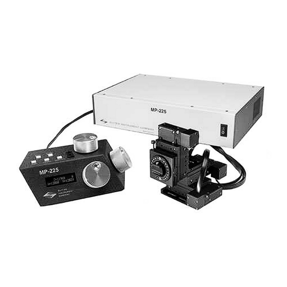
- Page 1 MP-225 Motorized Micromanipulator System Operation Manual Rev. 1.70 ( 20150316) One Digital Drive Novato, CA 94949 Voice: 415-883-0128 Web: www.sutter.com Fax: 415-883-0572 Email: info@sutter.com...
- Page 2 Copyright © 2015 Sutter Instrument Company. All Rights Reserved. MP-225 MOTORIZED MICROMANIPULATOR SYSTEM OPERATION MANUAL – REV. 1.70 (20150316)
-
Page 5: Dislaimer
Electrical • Operate the MP-225 using 110-120 V AC, 60 Hz, or 220-240 V AC., 50 Hz line voltage. This instrument is designed for connection to a standard laboratory power outlet (Overvoltage Category II), and because it is a microprocessor--controlled device, it should be accorded the same system wiring precautions as any 'computer type' system. -
Page 6: Electromagnetic Interference
Never touch any part of the micromanipulator electromechanical device while it is in operation and moving. Doing so can result in physical injury (e.g., fingers can be caught and pinched between the moving parts of the micromanipulator). MP-225 MOTORIZED MICROMANIPULATOR SYSTEM OPERATION MANUAL – REV. 1.70 (20150316) -
Page 7: Handling Micropipettes
Failure to do this may result in damage to the motors. This instrument contains no user-serviceable components — do not open the instrument casing. This instrument should be serviced and repaired only by Sutter Instrument or an authorized Sutter Instrument servicing agent. - Page 8 (This page intentionally left blank.) MP-225 MOTORIZED MICROMANIPULATOR SYSTEM OPERATION MANUAL – REV. 1.70 (20150316)
-
Page 9: Table Of Contents
2.5.3 Configuring the Inclusion of Y-Axis in Home and Work Pos. Robotic Moves.....7 3. OPERATING INSTRUCTIONS......................9 4. INSTRUCTIONS FOR CHANGING HANDEDNESS..............11 APPENDIX A. LIMITED WARRANTY....................13 APPENDIX B. ACCESSORIES......................15 APPENDIX C. FUSE REPLACEMENT.....................17 APPENDIX D. TECHNICAL SPECIFICATIONS................19 MP-225 MOTORIZED MICROMANIPULATOR SYSTEM OPERATION MANUAL – REV. 1.70 (20150316) - Page 10 TABLE OF FIGURES Figure 2-1. Position of locking setscrews on the front of the MP-225/M..........4 Figure 4-1. Changing manipulator handedness..................11 Figure C-1. Power entry module......................17 Figure C-2. Fuse holder...........................17 TABLE OF TABLES Table 2-1. Configuring the Angle of Diagonal-Mode Movements............7 Table 2-2.
-
Page 11: General Information
An extended version of Sutter Instrument’s rotary optical encoder (ROE) is the input device for the MP-225. The system provides for a synthetic 4th axis for diagonal advancement of the pipette; and up to 16 different angles can be configured. Speed and resolution of movement are easily selected with a multiple position thumbwheel, allowing fast/coarse movement and slow/ultra-fine movement in 10 increments. - Page 12 (This page intentionally left blank.) MP-225 MOTORIZED MICROMANIPULATOR SYSTEM OPERATION MANUAL – REV. 1.70 (20150316)
-
Page 13: Installation
Tightening the hex screw that threads from the side into each peg hole locks one axis to the next. The The MP-225 manipulator mechanical is set up for either right- or left-handed use. The handedness is determined when the system is ordered. -
Page 14: Figure 2-1. Position Of Locking Setscrews On The Front Of The Mp-225/M
X-axis firmly onto the plate, and re-tighten the locking hex set screws. Figure 2-1. Position of locking setscrews on the front of the MP-225/M. The modular construction allows for some flexibility in the connections between axes. In addition, the 3 axes can be used separately or assembled in non-standard configurations. -
Page 15: Electrical Connections
If you intend to use the right angle adapter (2852RA) with your MP-225 in order to rotate the manipulator 90 degrees, please see “Instructions used in Special Installations Only” near the end of this manual. The rotary dovetail on the front of the MP-225 provides a mounting surface for most common headstages. -
Page 16: Instructions Used In Special Installations Only
DIP Switches 1, 2, 3 and 4 set the angle of the Diagonal mode movement. The table gives the angles that can be used and the DIP-switch settings of switches 1,2,3 and MP-225 MOTORIZED MICROMANIPULATOR SYSTEM OPERATION MANUAL – REV. 1.70 (20150316) -
Page 17: Configuring Movement Display For Each Axis When Turning Roe Knob Clockwise
Home move and is moved back to whatever Y coordinate was recorded during Set-Work Pos. in the Work Pos. move. If switch 8 is set to 1, the Y axis is not moved (Y position MP-225 MOTORIZED MICROMANIPULATOR SYSTEM OPERATION MANUAL – REV. 1.70 (20150316) -
Page 18: Table 2-3. Configuring The Inclusion Of Y-Axis In Home And Work Pos. Robotic Moves
Home and Work Pos. moves). Table 2-3. Configuring the inclusion of Y-axis in Home and Work Pos. robotic moves. DIP Switch Include Y-Axis in Home and Work Pos. Robotic Moves MP-225 MOTORIZED MICROMANIPULATOR SYSTEM OPERATION MANUAL – REV. 1.70 (20150316) -
Page 19: Operating Instructions
Diag/Norm: Pressing the “Diag/Norm” button will cause the green LED to light, indicating the MP-225 is in Diagonal mode. When in this mode, rotation of the Z-axis knob produces diagonal movement. A second press will put the MP-225 back into Normal mode. When in diagonal mode, the X and Y knobs remain active, allowing you to re-adjust the X and Y positioning of the pipette as you approach a cell in diagonal mode. - Page 20 Center routine. If you find you need to run the center routine often (seeing EOT soon after running Center), you should contact Sutter Instrument Company for advice. MP-225 MOTORIZED MICROMANIPULATOR SYSTEM OPERATION MANUAL – REV. 1.70 (20150316)
-
Page 21: Instructions For Changing Handedness
To switch from left to right, simply reverse these directions. RIGHT HAND X-AXIS ROTATING LEFT HAND LOCKING SCREWS FOR CHANGING HANDEDNESS LOCKING SCREWS FOR CHANGING HANDEDNESS SWING GATE ROTATED AND TUMB SCREW MOVED Figure 4-1. Changing manipulator handedness. MP-225 MOTORIZED MICROMANIPULATOR SYSTEM OPERATION MANUAL – REV. 1.70 (20150316) - Page 22 (This page intentionally left blank.) MP-225 MOTORIZED MICROMANIPULATOR SYSTEM OPERATION MANUAL – REV. 1.70 (20150316)
-
Page 23: Appendix A. Limited Warranty
Warranty work will be performed only at the factory. The cost of shipment both ways is paid for by Sutter Instrument during the first three months this warranty is in effect, after which the cost is the responsibility of the customer. - Page 24 (This page intentionally left blank.) MP-225 MOTORIZED MICROMANIPULATOR SYSTEM OPERATION MANUAL – REV. 1.70 (20150316)
-
Page 25: Appendix B. Accessories
Hinged headstage mount M100106 Flat side panel for controller For use with MT- or MD-series stands/platforms, or any surface with 1-inch centered holes. XenoWorks® is a registered trademark of Sutter Instrument Company. MP-225 MOTORIZED MICROMANIPULATOR SYSTEM OPERATION MANUAL – REV. 1.70 (20150316) - Page 26 (This page intentionally blank.) MP-225 MOTORIZED MICROMANIPULATOR SYSTEM OPERATION MANUAL – REV. 1.70 (20150316)
-
Page 27: Appendix C. Fuse Replacement
Replace the active fuse with the spare and re-install the fuse holder and power cord. If the controller fails to power up with the new fuse installed, call Sutter Instrument technical support personnel for assistance. -
Page 28: Table C-1. Fuse Type And Rating
(Time Delay) S506-2A (RoHS) VAC) Littelfuse: 239 002 or 239.002.P (RoHS) “220” T1.0A, 250V Bussmann: GDC-1A or S506-1A (RoHS) (200 – 240 Littelfuse: 218 001 or 218 001.P (RoHS) VAC) MP-225 MOTORIZED MICROMANIPULATOR SYSTEM OPERATION MANUAL – REV. 1.70 (20150316) -
Page 29: Appendix D. Technical Specifications
MP-225/E Controller: 10 lb (4.5 kg.) ROE-225 Rotary Optical Encoder 3.118 lb (1.42 kg) Electrical: Input voltage (Mains): 100 – 120 VAC, 50/60 Hz 200 – 240 VAC, 50/60 Hz MP-225 MOTORIZED MICROMANIPULATOR SYSTEM OPERATION MANUAL – REV. 1.70 (20150316) -
Page 30: Table D-1. Mains Fuse Type And Rating
(RJ45 receptacle) 10 feet) NOTE:: A ferrite at the controller end is strongly recommended (Fair-Rite part number 0443164-251). Fair-Rite Products Corp., P.O. Box J, One Commercial Row, Wallkill, NY, 12589, USA MP-225 MOTORIZED MICROMANIPULATOR SYSTEM OPERATION MANUAL – REV. 1.70 (20150316) - Page 31 .............1 travel..............19 mains fuse..............20 fuses ..............iii unpacking..............3 voltage..............19 modular construction..........3 mounting instructions..........3 voltage mains..............19 notes user..............22 warranty..............13 weight ..............19 packaging..............3 MP-225 MOTORIZED MICROMANIPULATOR SYSTEM OPERATION MANUAL – REV. 1.70 (20150316)
- Page 32 NOTES MP-225 MOTORIZED MICROMANIPULATOR SYSTEM OPERATION MANUAL – REV. 1.70 (20150316)
Need help?
Do you have a question about the MP-225 and is the answer not in the manual?
Questions and answers