Table of Contents
Advertisement
Quick Links
Overview
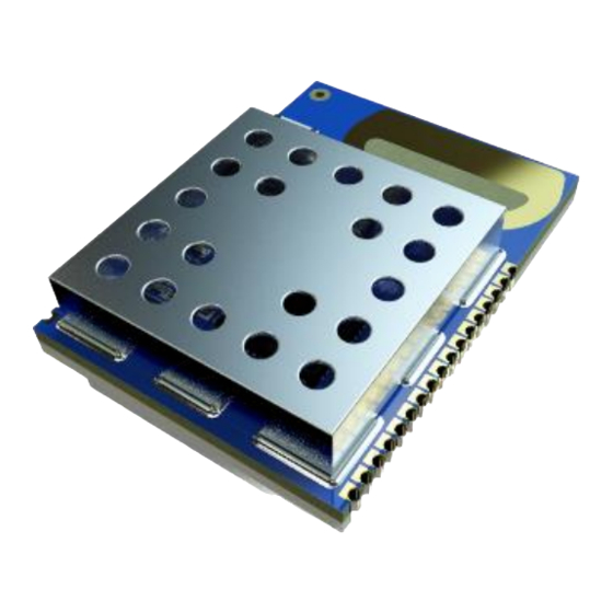
The DWM1001 module is based on Decawave's DW1000 Ultra
Wideband (UWB) transceiver IC, which is an IEEE 802.15.4-
2011 UWB implementation. It integrates UWB and Bluetooth®
antenna, all RF circuitry, Nordic Semiconductor nRF52832 and
a motion sensor.
Key Features
•
Ranging accuracy to within 10cm.
•
UWB Channel 5 printed PCB antenna (6.5 GHz)
•
6.8 Mbps data rate
•
60 m line-of-sight range typical
•
IEEE 802.15.4-2011 UWB compliant
•
Nordic Semiconductor nRF52832
•
Bluetooth® connectivity
•
Bluetooth® chip antenna
•
Motion sensor: 3-axis accelerometer
•
Current consumption optimised for low power sleep mode: <15μA
•
Supply voltage: 2.8 V to 3.6 V
•
Size: 19.1 mm x 26.2 mm x 2.6 mm
Key Benefits
•
Enables anchors, tags & gateways to quickly get an entire RTLS system up-and-running
•
Accelerates product designs for faster Time-to-Market & reduced development costs
•
Ready-to-go embedded firmware to minimise software development
•
Over-the-air updates
•
User API to DWM1001 firmware (available as a library) for user code customisation
•
On-board Bluetooth® SMART for connectivity to phones/tablets/PCs
•
SPI, UART and Bluetooth® APIs to access DWM1001 firmware from an external device
•
Low-power hardware design and software architecture for longer battery life
RESET
BT_WAKE_UP
READY
UART [1:0]
SPI S2* [3:0]
I2C [1:0]
相关的中文文档请参考 www.decawave.com/china
UWB Antenna
BLE Antenna
BLE
UWB
Microprocessor
Transceiver
SPI M1*
Nordic
Decawave
nRF52832
DW1000
64 MHz ARM
Cortex M4
IRQ
1V8
3- Axis Motion
Detector
STM
LIS2DH12TR
*SPI M1 is nRF52 SPI master 1, SPI S2 is SPI slave 2
High Level Block Diagram
4
GPIO
12
GPIO
SWD[1:0]
DC-DC
VCC
Converter
2.8 V – 3.6 V
GND
Advertisement
Table of Contents

Summary of Contents for decaWave DWM1001
- Page 1 Ready-to-go embedded firmware to minimise software development • Over-the-air updates • User API to DWM1001 firmware (available as a library) for user code customisation • On-board Bluetooth® SMART for connectivity to phones/tablets/PCs • SPI, UART and Bluetooth® APIs to access DWM1001 firmware from an external device •...
-
Page 2: Table Of Contents
2.1.2 Transmitter Calibration ....6 ......19 ODULE OLDER ROFILE 2.1.3 Antenna Delay Calibration ....6 ORDERING INFORMATION ......20 DWM1001 PIN CONNECTIONS ..... 7 ...... 20 APE AND NFORMATION .......... 7 UMBERING GLOSSARY ..........21 ........7 ESCRIPTIONS REFERENCES ..........22 ELECTRICAL SPECIFICATIONS ...... - Page 3 ............9 FUNCTION 4: I2C I2C ....... 9 ABLE SLAVE DEVICES ADDRESS 5: DWM1001 O .... 10 ABLE PERATING ONDITIONS 6: DWM1001 DC C ....10 ABLE HARACTERISTICS 7: DWM1001 R AC C ... 10 ABLE ECEIVER HARACTERISTICS 8: DWM1001 T...
- Page 4 Decawave product would reasonably be expected to cause severe personal injury or death. Decawave customers using or selling Decawave products in such a manner do so entirely at their own risk and agree to fully indemnify Decawave and its representatives against any damages arising out of the use of Decawave products in such safety-critical applications.
-
Page 5: Overview
DWM1001 Datasheet VERVIEW The block diagram on page 1 of this data sheet shows the major sections of the DWM1001. An overview of these blocks is given below. 1.1 UWB Transceiver DW1000 The module has a DW1000 UWB transceiver mounted on the PCB. The DW1000 uses a 38.4 MHz reference crystal. -
Page 6: Dwm1001 Calibration
In order to measure range accurately, precise calculation of timestamps is required. To do this the antenna delay must be known. The DWM1001 allows this delay to be calibrated and provides the facility to compensate for delays introduced by PCB, external components, antenna and internal DWM1001 delays. -
Page 7: Dwm1001 Pin Connections
DWM1001 Datasheet 3 DWM1001 P ONNECTIONS 3.1 Pin Numbering DWM1001 module pin assignments are as follows (viewed from top): - SWD_CLK RESETn SWD_DIO BT_WAKE_UP GPIO_10 GPIO_2 GPIO_9 GPIO_3 GPIO_12 SPIS_CSn GPIO_14 SPIS_CLK GPIO_22 SPIS_MOSI GPIO_31 SPIS_MISO GPIO_30 GPIO_8 GPIO_15 GPIO_27... - Page 8 Generated interrupt from the device. [N] P0.26 Indicates events such as SPI data ready, or READY location data ready. See the function dwm_int_cfg() in the DWM1001 Firmware API Guide for details[5]. UART_TX, This is also the ADC function of the UART_TX [N] P0.05 nRF52 General purpose I/O pin of the DW1000.
-
Page 9: Table 2: Explanation Of Abbreviations
PO.28 I2C_SCL DW1000’s GPIOs 5,6 control the DW1000 SPI mode configuration. Within the DWM1001 module, those GPIOs are unconnected and will be internally pulled down. Consequently, SPI will be set to mode 0. For more details, please refer to DW1000 data sheet [2]. -
Page 10: Electrical Specifications
DWM1001 Datasheet LECTRICAL PECIFICATIONS = 25 ˚C for all specifications The following tables give detailed specifications for the DWM1001 module. T given. 4.1 Nominal Operating Conditions Table 5: DWM1001 Operating Conditions Parameter Min. Typ. Max. Units Condition/Note ˚C Operating temperature... -
Page 11: Receiver Sensitivityc
Output Channel Power dBm/500MHz Output power variation with Using on board temperature* compensation. * If using the pre-loaded embedded firmware of the DWM1001 module, otherwise see the DW1000 datasheet © Decawave Ltd 2017 Subject to change without notice Version 1.10 Page 11... -
Page 12: Absolute Maximum Ratings
ESD (Human Body Model) 2000 Note that 3.6 V is the max voltage DWM1001 pins other than VCC, VDDIO and GND that may be applied to these pins Stresses beyond those listed in this table may cause permanent damage to the device. This is a stress rating only;... -
Page 13: Figure 2: Power Consumption During
OWER ONSUMPTION The following Figures give power profiles for the DWM1001 on a DWM1001-DEV PCB when used for Two Way Ranging, see Figure 2. Peak values are given. Figure 2 shows an example of the power consumption of a DWM1001 tag running the factory loaded firmware. -
Page 14: Figure 3. Antenna Radiation Pattern
NTENNA ERFORMANCE This section details antenna radiation patterns for the DWM1001-Dev board. Figure 3 presents a view of the measurement planes considered in this document. Table 11 shows antenna radiation patterns for the DWM1001 module mounted on the DWM1001-Dev board. -
Page 15: Table 11. Antenna Radiation Patterns
XZ Plane: 344 352 180° 270° 90° 0° Theta XY Plane: 344 352 90° 180° Theta 0° 270° YZ Plane: 344 352 180° 90° 270° Theta 0° © Decawave Ltd 2017 Subject to change without notice Version 1.10 Page 15... -
Page 16: Figure 4: Dwm1001 Application
(Note: the rectangular area above the shield on the module is the antenna area) It is also important to note that the ground plane on the application board affects the DWM1001 antenna radiation pattern. There must be a minimum spacing of 10 mm (d) without metal either side of the module antenna. -
Page 17: Package Information
DWM1001 Datasheet ACKAGE NFORMATION 8.1 Module Drawings All measurements are given in millimetres. Figure 5: Module Package Size (units: mm) © Decawave Ltd 2017 Subject to change without notice Version 1.10 Page 17... -
Page 18: Module Land Pattern
DWM1001 Datasheet 8.2 Module Land Pattern The diagram below shows the DWM1001 module land pattern. Figure 6: DWM1001 Module Land Pattern (units: mm) 8.3 Module Marking Information Each module has a label on the shield with a serial number in the following format:... -
Page 19: Module Solder Profile
DWM1001 Datasheet 8.4 Module Solder Profile Figure 7: DWM1001 Module Solder Profile © Decawave Ltd 2017 Subject to change without notice Version 1.10 Page 19... -
Page 20: Ordering Information
DWM1001 Datasheet RDERING NFORMATION 9.1 Tape and Reel Information Figure 8: DWM1001 Tape and Reel Dimensions © Decawave Ltd 2017 Subject to change without notice Version 1.10 Page 20... -
Page 21: Glossary
TDOA Arrival the transmitter. A number of such TDOA measurements at different locations can be used to uniquely determine the position of the transmitter. Refer to Decawave’s website for further information. Ultra Wideband A radio scheme employing channel bandwidths of, or in excess of, 500MHz... -
Page 22: Stm Icroelectronics
[3] Decawave DW1000 User Manual www.decawave.com [4] STMicroelectronics LIS2DH12TR www.st.com [5] DWM1001 Firmware API Guide [6] DWM1001 Firmware User Guide [7] IEEE802.15.4-2011 or “IEEE Std 802.15.4™‐2011” (Revision of IEEE Std 802.15.4-2006). IEEE Standard for Local and metropolitan area networks – Part 15.4: Low-Rate Wireless Personal Area Networks (LR- WPANs). -
Page 23: About Decawave
(RTLS) and Ultra Low Power Wireless Transceivers in areas as diverse as manufacturing, healthcare, lighting, security, transport, inventory & supply chain management. Further Information For further information on this or any other Decawave product contact a sales representative as follows: - Decawave Ltd Adelaide Chambers...
Need help?
Do you have a question about the DWM1001 and is the answer not in the manual?
Questions and answers