
Related Manuals for BFGoodrich Stormscope II Series

Summary of Contents for BFGoodrich Stormscope II Series
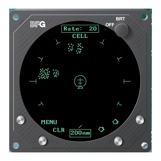
- Page 1 $7.00 U.S. Pilot’s Guide for the Stormscope ® Series II Weather Mapping Systems Model WX-950 Rate CELL MENU 200nm...
- Page 2 The system, the original, most ac- Stormscope curate weather mapping system is now manufactured by BFGoodrich Avion- ics Systems. Fly with Greater Confidence You now own the leading instrument in the world for airborne detection and mapping of thunderstorms.
- Page 3 BFGoodrich Avionics Systems. No government or other contractual support or relationship what- soever has existed which in any way affects or mitigates proprietary rights of BFGoodrich Avionics Systems in these developments. Methods and apparatus disclosed herein may be subject to U.S. Pat- ents existing or applied for.
- Page 4 Safety Summary The following warnings and cautions appear in this guide and are repeated here for emphasis: WARNING The illustrations in this guide are only examples. Never use ® your Stormscope system to attempt to penetrate a thunder- storm. The FAA Advisory Circular, Subject: Thunderstorms, and the Airman’s Information Manual (AIM) recommend that you “avoid by at least 20 miles any thunderstorm iden- tified as severe or giving an intense radar echo.”...
-
Page 5: Table Of Contents
Table of Contents Page List of Illustrations ................v List of Tables ................... v Chapter 1 System Description ............. 1-1 General Description ................... 1-1 Display/Processor .................. 1-1 Antenna ....................1-1 Functional Description ................1-2 Cell Display Mode ................. 1-2 Strike Display Mode ................1-3 Features ...................... - Page 6 ® Table of Contents Stormscope WX-950 Table of Contents (Continued) Page Non-Recoverable Faults ..............3-15 Fatal Faults ................... 3-16 Chapter 4 Weather Display Interpretation ........4-1 Introduction ....................4-1 Radial Spread ..................4-2 Typical Patterns ..................4-2 Three Clusters within the 200 nmi Range Ring ........4-2 Two Clusters within the 200 nmi Range Ring ........
- Page 7 List of Illustrations Figure Title Page WX-950 System Components ............. 1-1 WX-950 Functional Diagram ............1-2 WX-950 Weather Views .............. 1-3 Electrical Discharges in Thunderstorms ........2-1 Discharge Rate a Function of Wind Shear ........2-2 Controls and Indicators ............... 3-1 Self Test In Progress ..............
-
Page 8: Chapter 1 System Description
® Stormscope WX-950 System Description Chapter 1 System Description General Description ® Series II Weather Mapping System, model WX-950 detects Stormscope electrical discharges associated with thunderstorms within a 200 nmi radius of the aircraft and displays the location of the associated thunderstorms. ®... -
Page 9: Functional Description
® System Description Stormscope WX-950 better than other systems due to its patented sense channel technology. The ® antenna has also been improved for the model WX-950 sys- Stormscope tem to help filter out pulsed noise from sources other than atmospheric electrical discharges. -
Page 10: Strike Display Mode
® Stormscope WX-950 System Description Rate Rate CELL STRIKE MENU MENU 200nm 200nm 360° View, CELL Display Mode 120° View, STRIKE Display Mode Figure 1-3. WX-950 Weather Views Strike Display Mode ® In the strike display mode, the Stormscope system immediately plots an “x”... - Page 11 ® System Description Stormscope WX-950 • Heading stabilization – automatically repositions discharge points on the display relative to the latest aircraft heading when connected to a compat- ible heading system • Local and remote clear – allows operator to clear displayed discharge points ®...
-
Page 12: Chapter 2 Storm Mapping Principles
® Stormscope WX-950 Storm Mapping Principles Chapter 2 Storm Mapping Principles Anatomy of a Thunderstorm ® model WX-950 is intended to help pilots avoid the dangers Stormscope associated with thunderstorms (convective wind shear, lightning, icing, torna- ® does, etc.). The Stormscope system locates thunderstorms by detecting the electrical discharges that thunderstorms always generate. -
Page 13: Stages Of A Thunderstorm
® Storm Mapping Principles Stormscope WX-950 Figure 2-2 shows that the rate of electrical discharges detected in an area is directly related to the amount of convective wind shear turbulence present. In fact, as convective wind shear increases, the rate of electrical discharges in- creases at an increasing rate. -
Page 14: Storm Mapping Technology
® Stormscope WX-950 Storm Mapping Principles Storm Mapping Technology ® The Stormscope System and Weather Radar ® The storm mapping technology used in the Stormscope system is funda- mentally different than the technology used in weather radar. Weather ra- dar operates by transmitting UHF radio waves in the direction of interest ®... -
Page 15: Chapter 3 Operation
1 2 3 4 5 6 7 8 9 10 SELF-TEST WX-950 ERROR 02 SYSTEM TEST Processor Fault IN PROGRESS . . . ALL TESTS PASSED BFGoodrich Continued operation FlightSystems, Inc. is not possible (C) 1995 Self-Test Screen Error Message Figure 3-1. Controls and Indicators Table 3-1. - Page 16 ® Operation Stormscope WX-950 Table 3-1. Controls and Indicators (Continued) Item Name Description Discharge Points large area. A dense cluster indicates an intense (Continued) thunderstorm. The size of the discharge points increases as the selected range decreases in order to enhance the storm clustering effect on the ®...
- Page 17 ® Stormscope WX-950 Operation Table 3-1. Controls and Indicators (Continued) Item Name Description 10 Azimuth Marker The azimuth markers help to quantify the angular location of electrical discharges relative to the aircraft. In the 360° view, 8 short r adial markers are spaced 30°...
-
Page 18: Operating Instructions
® Operation Stormscope WX-950 Table 3-1. Controls and Indicators (Continued) Item Name Description 17 Highlighted A highlighted menu item identifies the currently Menu Item selected menu item. 18 Menu Item Status These indicators display the status of the test or Indicator function named in the menu item. -
Page 19: Self Test In Progress
® Stormscope WX-950 Operation SELF-TEST WX-950 SYSTEM TEST IN PROGRESS . . . BFGoodrich FlightSystems, Inc. (C) 1995 Figure 3-2. Self Test In Progress SELF-TEST WX-950 SYSTEM TEST IN PROGRESS . . . ALL TESTS PASSED BFGoodrich FlightSystems, Inc. (C) 1995 Figure 3-3. -
Page 20: Switch To The Menu Screen
® Operation Stormscope WX-950 Switch to the MENU Screen a. From either of the two weather views (360° or 120°) press the MENU button. (See figure 3-1.) The display will switch to the MENU screen. The first menu item, Weather View, will be highlighted. (See figure 3-5.) MENU Weather View... -
Page 21: Method B
® Stormscope WX-950 Operation The position of the 360° and 120° button labels depends on the last weather view screen displayed. If the 360° weather view screen was displayed last, the upper left button will be labeled 120° and the lower left button will be labeled 360°. If the 120° weather view screen was displayed last, the upper left button will be la- beled 360°... -
Page 22: Select The Range
® Operation Stormscope WX-950 Select the Range a. Switch to one of the two weather views (360° or 120°). b. Press the up arrow button repeatedly to step up through the operating ranges 25, 50, 100, and 200 nmi. c. Press the down arrow button repeatedly to step down through the operating ranges 200, 100, 50, and 25 nmi. -
Page 23: Switch Between Wx Display Modes
® Stormscope WX-950 Operation Switch Between WX Display Modes ® The WX Display menu item selection determines how the Stormscope system will display electrical activity on both the 360° and 120° weather views. (WX stands for weather and is defined as electrical activity.) a. -
Page 24: Toggle Heading Stabilization On And Off
® Operation Stormscope WX-950 MENU Weather View Display CELL Self Test PASSED HDG Stabilize 360$ TEST Figure 3-8. MENU Screen with Self Test Highlighted c. Press the TEST button to run the operator-initiated self test. ® system will switch to the SELF-TEST screen (fig- Stormscope ure 3-2) and will begin the self test. -
Page 25: Turn Off The Stormscope ® System
® Stormscope WX-950 Operation a. Switch to the MENU screen. b. Scroll through the menu items until the HDG Stabilize menu item is highlighted. (See figure 3-9.) The current state of the heading stabilization feature is listed to the right of the highlighted menu item. An “N/A” displayed here means that heading stabilization is not available due to your particular in- stallation configuration. -
Page 26: Error Messages
® Operation Stormscope WX-950 Error Messages ® Stormscope system detects most common faults and displays error mes- sages indicating the nature of the faults and which functions may be inopera- ® tive. These error messages enable your authorized dealer or BFG Stormscope Avionics Systems factory service personnel to quickly diagnose and correct the fault. - Page 27 ® Stormscope WX-950 Operation Table 3-2. Error Messages (Continued) Error Message Fault Source Type* Recommended Action Error 16 Antenna is not NF/R Press any button to continue Antenna Fault able to receive without weather mapping or forward the functions. See your dealer for necessary service.
-
Page 28: Non-Fatal Faults
® Operation Stormscope WX-950 Table 3-2. Error Messages (Continued) Error Message Fault Source Type* Recommended Action Error 23 No 400 Hz NF/R Press any button to continue Invalid Synchro reference without heading stabilization. See your dealer for service. Error 24 Mic key (inhibit NF/R Check your microphone key Mic Key Stuck... -
Page 29: Recoverable Faults
® Stormscope WX-950 Operation Recoverable Faults A recoverable fault is one that allows the affected functions to auto- matically resume proper operation after the fault goes away. The associ- ated error message will disappear within 10 seconds after the fault goes away. -
Page 30: Fatal Faults
® Operation Stormscope WX-950 Rate STRIKE ERROR 23 Invalid Synchro Ref Heading Stabilization is Not Available Press any key MENU to continue 100nm Figure 3-14. Weather View with a Figure 3-13. Error Message for a Heading Flag Heading-Related Fault Fatal Faults If a fatal fault occurs, all functions will cease to operate and the message “Continued operation is not possible”... -
Page 31: Chapter 4 Weather Display Interpretation
® Stormscope WX-950 Weather Display Interpretation Chapter 4 Weather Display Interpretation WARNING The illustrations in this guide are only examples. Never use ® your system to attempt to penetrate a thunder- Stormscope storm. The FAA Advisory Circular, Subject: Thunderstorms, and the Airman’s Information Manual (AIM) recommend that you “avoid by at least 20 miles any thunderstorm iden- tified as severe or giving an intense radar echo.”... -
Page 32: Radial Spread
Discharge points in radial spread do not necessarily indicate the exact lo- cation of atmospheric electrical discharges. To counteract radial spread, BFGoodrich Avionics Systems applied its extensive research in lightning detection to develop enhanced lightning positioning algorithms. These al- gorithms (used only in the cell display mode) greatly reduce radial spread and improve the depiction of thunderstorms on the display. -
Page 33: Three Clusters Within 200 Nmi
® Stormscope WX-950 Weather Display Interpretation Rate Rate CELL STRIKE MENU MENU 200nm 200nm Figure 4-2. Three Clusters Within 200 nmi Rate Rate CELL STRIKE MENU MENU 100nm 100nm Figure 4-3. Range Changed to 100 nmi Pilot’s Guide... -
Page 34: Two Clusters Within The 200 Nmi Range Ring
® Weather Display Interpretation Stormscope WX-950 ® range 75 nmi. You’ll notice on the right-hand screen (strike Stormscope display mode) that there is less radial spread than there was in the 200 nmi range. It is true in general that radial spread is reduced on the shorter ranges. Two Clusters within the 200 nmi Range Ring ®... -
Page 35: Aircraft Progresses 100 Nmi
® Stormscope WX-950 Weather Display Interpretation Rate 117 Rate 125 CELL STRIKE MENU MENU 200nm 200nm Figure 4-5. Range Set at 200 nmi Aircraft Progresses 100 nmi Figure 4-6 shows that the aircraft has maintained its heading and progressed 100 nmi. The two thunderstorms off the nose of the aircraft appear to have expanded horizontally on the screen. -
Page 36: Aircraft Progresses 100 Nmi
® Weather Display Interpretation Stormscope WX-950 Rate 118 Rate 127 CELL STRIKE MENU MENU 200nm 200nm Figure 4-6. Aircraft Progresses 100 nmi Rate Rate CELL STRIKE MENU MENU 100nm 100nm Figure 4-7. Range Changes to 100 nmi Pilot’s Guide... -
Page 37: Special Patterns
® Stormscope WX-950 Weather Display Interpretation Rate Rate CELL STRIKE MENU MENU 100nm 100nm Figure 4-8. Aircraft Turns To Avoid Thunderstorms Special Patterns Randomly Scattered Discharge Points Atmospheric instability associated with cumulus clouds, or developing or dissipating thunderstorms could cause randomly scattered discharge points ®... - Page 38 ® Weather Display Interpretation Stormscope WX-950 Rate Rate CELL STRIKE MENU MENU 200nm 200nm Figure 4-9. Randomly Scattered Discharge Points Rate Rate CELL STRIKE MENU MENU 25nm 25nm Figure 4-10. Cluster and Splattering Within 25 nmi Pilot’s Guide...
-
Page 39: Discharge Points Off Aircraft's Nose
® Stormscope WX-950 Weather Display Interpretation You’ll notice in figure 4-10 that the location of random, individual dis- charge points is about the same on both the cell and storm display modes. ® This is true because in the cell display mode, the Stormscope system plots every electrical discharge detected within the 25 nmi range at the exact... -
Page 40: Line Of Discharge Points While Taxiing
® Weather Display Interpretation Stormscope WX-950 Line of Discharge Points While Taxiing Passing over a cable beneath the taxiway can cause a line of discharge points across the screen as shown in figure 4-12. Similar concentrations of discharge points across the screen may appear while taxiing due to electri- cal signals from nearby equipment such as arc welders or subway rails. -
Page 41: Developing Cluster Within The 25 Nmi Range Ring
® Stormscope WX-950 Weather Display Interpretation Developing Cluster Within the 25 nmi Range Ring Figure 4-13 shows a developing thunderstorm 12 nmi from the aircraft. If you see a screen such as this with a developing cluster within the 25 nmi range ring, you should change course to avoid the storm and continue to ®... -
Page 42: Chapter 5 Specifications, Maintenance, & Service
Chapter 5 Specifications, Maintenance, & Service Specifications ® Table 5-1 lists the specifications for the system. Stormscope ® Table 5-1. WX-950 Stormscope System Specifications PART NUMBER: 805-10950-( ) FEATURES: Selectable weather ranges: 25, 50, 100, or 200 nautical miles Selectable weather views: 120 or 360 degrees Selectable display modes: Cell or Strike Integral CRT display screen Built-in self tests... -
Page 43: Maintenance & Service
® Specifications, Maintenance, & Service Stormscope WX-950 Maintenance & Service ® Your Stormscope system should be checked for proper operation and perfor- mance at least once a year, preferably before the thunderstorm season. Your ® authorized dealer has the specialized test equipment and train- Stormscope ®... -
Page 44: Chapter 6 Warranty Information
® system is warranted for 2 years from the date of installation Stormscope (not to exceed 30 months from the date of shipment from BFGoodrich Avion- ics Systems) subject to the following limitations. Warranty Statement BFGoodrich Avionics Systems, (hereinafter called BFGAS), warrants each... -
Page 45: Related Policies And Procedures
Written notification of the transaction must be submitted by the initial recipient of the war- ranty to: ATTENTION: WARRANTY ADMINISTRATOR BFGoodrich Avionics Systems 5353 52nd Street, S.E. Grand Rapids, MI 49588-0873 U.S.A. b. Equipment must be installed by a BFG Avionics Systems authorized dealer or installer. -
Page 46: Appendix A Dealer Information & Annual Performance Check
Note ® To ensure that a repaired system meets FAA TSO, Stormscope major government regulatory agencies approvals outside the U.S.A., and BFGoodrich Avionics Systems performance stan- ® dards, your system must be reinstalled and tested Stormscope ® by an authorized dealer. - Page 47 009-10951-001 (Rev. 00, 2/9/96) ® Stormscope Series II Weather Mapping Systems...
Need help?
Do you have a question about the Stormscope II Series and is the answer not in the manual?
Questions and answers