VeEX TX300s User Manual
Hide thumbs
Also See for TX300s:
- User manual (107 pages) ,
- User manual (109 pages) ,
- User manual (123 pages)
Table of Contents
Advertisement
Advertisement
Table of Contents

Related Manuals for VeEX TX300s


Summary of Contents for VeEX TX300s
-
Page 2: Table Of Contents
Table of Contents 1.0 About This User Manual 2.0 Safety Information 3.0 Introduction 3.1 Platform Overview 3.2 Front Panel 3.2.1 LED's 3.2.2 Key Pad 3.2.3 Touch Screen 3.3 Battery 3.3.1 Battery Overdraw Protection 3.4 Hardware Configurations 3.5 Home Screen 3.6 Quick Access Menu 4.0 Getting Started 4.1 Initial Settings 4.1.1 Change language and user interface style... - Page 3 5.1.6 Global Settings 5.1.7 Date and Time 5.1.8 Remote Access 5.1.9 EZ Remote 5.1.10 VF Noise Calibration (Microphone) 5.1.11 Maps Downloader 5.1.12 High Precision Clock Sources 5.2 Help 5.3 VeExpress 5.4 R-Server (Advanced Management) 5.5 Software Upgrade 6.0 File Manager 6.1 File Manager: Working with Saved Results, Profiles, Images 6.2 USB Memory Browser 6.3 Manage SD Card...
- Page 4 7.6 Web Browser 8.0 Warranty and Software 9.0 Certification and Declarations 10.0 About VeEX Go back to TOC TX300s_Platform_Manual_RevB00 Page 4 of 104...
-
Page 5: About This User Manual
(c) Copyright 2019 VeEX Inc. All rights reserved. VeEX, VePAL are registered trademarks of VeEX Inc. and/or its affiliates in the USA and certain other countries. All trademarks or registered trademarks are the property of their respective companies. No part of this document may be reproduced or transmitted electronically or otherwise without written permission from VeEX Inc. -
Page 6: Safety Information
Do not operate the instrument in the presence of flammable gases or fumes or any other combustible environment. VeEX Inc. assumes no liability for the customer's failure to comply with safety precautions and requirements. - Page 7 50% of its capacity. Spare battery packs should be charged and used at least once a year to prevent over-discharge (rotate them regularly). It is recommended to charge and use battery packs at least every three months. Battery packs must not go without recharging (reconditioning) for more than six months.
-
Page 8: Introduction
3.0 Introduction to TX300s Series ® VeEX TX300s series test sets are portable test solutions, with flexible configurations, for Core, Transport, Metro and Access Networks carrying Data, Voice, and Video. All-in-one hardware platform reduces CAPEX The VeExpress ecosystem allows users to Buy, Rent, Lease-to-own and share test feature licenses to optimize OPEX... -
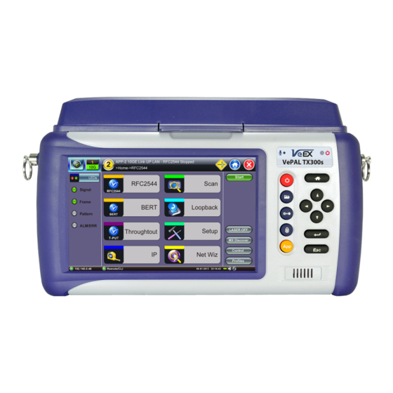
Page 9: Front Panel
3.1 TX300s Overview Go back to TOC 3.2 Front Panel 3.2.1 LEDs Power LED: A single LED indicates the power state of the unit. The LED is off when the unit is powered off. The LED is green when the unit is powered on. -
Page 10: Key Pad
Battery Charging time The total charging time depends on the remaining battery capacity percentage and the actual current load in the TX300s. An idle TX300s would recharge faster than an active one. -
Page 11: Battery Overdraw Protection
For safety reasons, the battery charging time is always limited to a maximum of three hours If the TX300s is being used while charging and a full charge (100% capacity) cannot be achieved within three hours, the charging will automatically stop. -
Page 12: Hardware Configurations
3.4 Hardware Configurations The following are examples of some test modules available for the TX300s platform. Please refer to their individual datasheets and manuals for further details. For an up-to-date list of modules available, please visit www.veexinc.com/TX300S Two 300SM Modules - Two Single Port Groups... - Page 13 One 320S Module - Single Port Group Configurable as an economical Single-Group Dual-Port option (Dual Tests) Universal multi-service test module offers OTN/SDH/SONET/PDH/DSn, Carrier Ethernet, MPLS, Fibre Channel, CPRI/OBSAI, Synchronization and more Additional Technologies, Rates and Test Features can be added later, via SW licenses Perfect companion to the OTDR hardware option One 340SM Module - Single Port Group Flexible, all-in-one multi-service test solution, from 64kbps to 16 Gbps (can be combined with 100G and OTDR modules)
- Page 14 fuctions One 100G Module Available with CFP4 or QSFP28 for 100GE and OTU4 applications Supports IEEE 802.3bj Clause 91RS-FEC as required for SR4 (QSFP28) QSFP+ for 40GE, OTU3 External clock interface 150 ppm clock offset generation Soft LED indicators OTDR Module Fiber Optics, Transport and Service Verification, Testing &...
-
Page 15: Home Screen
Go back to TOC 3.5 Home Screen Go back to TOC TX300s_Platform_Manual_RevB00 Page 15 of 104... -
Page 16: Quick Access Menu
3.6 Quick Access Menu This multi-tasking section provides convenient and immediate access to system features, connectivity, accessories, results, etc. Those features are always available, independently of whether tests are running or not. Go back to TOC TX300s_Platform_Manual_RevB00 Page 16 of 104... -
Page 17: Getting Started
4.0 Getting Started - TX300s 4.1 Initial Settings 4.1.1 Change language and user interface style Before using the platform, set the language and user interface style as needed. By default, the user interface style is set to USA if the unit is shipped to North America and to International if the unit is shipped to outside North America. -
Page 18: Launching Test Applications
4.2 Launching Test Applications The Test Cards summary/status screen offers intuitive test application management (launch, monitor, switching and release). Each test card is associated with a test module (orange numbers) and their individual test port groups (white numbers); capable of showing two, three or four possible tests, depending on the capabilities of the modules installed in the test platform. -
Page 19: Understanding Test Application Gui
2. Select the Technology Group. 3. Select the desired Test Mode based on the application to be tested. 4. Tap on the OK button to confirm. The test port group is assigned to the selected test application. Required software/firmware is loaded. Go back to TOC 4.3 Understanding Test Application GUI A. -
Page 20: Utilities
5.0 Utilities 5.1 Platform Settings This section provides settings for the global parameters of the test set or platform (system settings). Settings Menu Go back to TOC 5.1.1 About This section provides information about the software version, serial number, and MAC address of the management port of the unit, as well as a list of software licenses (optional test features) currently loaded in the test set. -
Page 21: Screen Calibration
License Keys for manual activation. License keys must be requested at the time new options are purchased. To activate new features, tap on the expired item and enter the Activation Code that you received from VeEX, VeEX partner or your manager. Press Activate to complete the licensing process. -
Page 22: Bluetooth
5.1.3 Bluetooth VeEX products support a micro USB Bluetooth adaptor offering wireless connectivity up to 10 meters (30 feet). Ultra compact and portable, the adaptor provides an untethered connection between the tester and other Bluetooth compatible devices such as a Notebook PC or cell phone, so the user can transfer test result files quickly and easily without having use memory sticks or Ethernet connections. - Page 23 Bluetooth - Devices Tab Bluetooth - Devices Tab Bluetooth - Connection - Passcode Setup Press Scan to check for available bluetooth devices. Once scanning is complete, a list of discovered Bluetooth devices will be listed. Please ensure the peripheral device is set to Discoverable during Scanning and Pairing operation. Press Pair BT to begin the pairing process.
- Page 24 peripheral device (PC or Mobile Phone) in order to pair successfully. Enter the last 4 digits of the V300 serial number as shown in the Connection tab. Once paired, click the Services button at the bottom of the screen to check the service attributes. To upload test results via Bluetooth and Mobile phone to a UMTS or 3G network, full data upload service will be required.
-
Page 25: Power
5.1.4 Power This section provides information about current power source and information about the battery gauge. Tap on the battery icon, on the top bar, to bring battery charge and estimated autonomy information. Utility Settings - Battery Power Go back to TOC 5.1.5 Backlight This section provides backlight control of the unit. -
Page 26: Global Settings
Backlight - AC Power Brightness: The user can select the brightness level for Battery and AC operation modes. Backlight - Brightness Go back to TOC 5.1.6 Global Settings General Setting Language: An alternative language for the user interface Units: Measurement system (English - feet or Metric - meter) Audible Alarm: When enabled, the test set's buzzer will sound (beep) when alarms and errors are being detected Show Password: Hides/unhides username and password information associated with FTP and related IP functions User Interface: The USA user interface version presents SONET/DSn application-oriented menus, while the International... - Page 27 Utility Settings - General Setting Storage Setting File Name Prefix: Tap on the box to enter the file name prefix using the pop up alphanumeric keypad. Profile Deleting: Auto Delete or Prompt User Profile Saving: Auto Overwrite or Prompt User Result Saving: Manual or Prompt User Advanced Saving: On/Off.
-
Page 28: Date And Time
Utility Settings - Lock/Save Screen Go back to TOC 5.1.7 Date and Time This screen allows the user to set the date and time according to time zone or user requirement. Daylight savings are automatically enabled in the utility. Date Setup TX300s_Platform_Manual_RevB00 Page 28 of 104... - Page 29 Time Zone Setup Go back to TOC TX300s_Platform_Manual_RevB00 Page 29 of 104...
-
Page 30: Remote Access
Using command line interface (CLI) scripts via SSH connection ReVeal RXTS PC software This VeEX application allows users to connect to the test set, using the platform’s IP address. ReVeal intuitive user interface offers the following functions: Test Profiles Management: Create, Edit, upload and download complex Ethernet and Fibre Channel test profiles (BERT,... - Page 31 Use this function to View, Download, Delete, Filter and convert saved Test Results to PDF Screen Shots View, Download (PNG format), Copy, Delete and convert to PDF any screens captured using the TX300s Lock button Remote Control (Screen Mirroring) It is similar to using VNC, but in this case no VNC client installation is required. It uses a standard Java-based web browser as a client.
- Page 32 certain tablets. The web browser must support Java (tm) Web Super User Password: Defines the password for users allowed to control the test set via standard web browser clients Web Regular User Password: Defines the password given to users who are only allowed to view the test set current screen via standard web browser clients, but not make any changes to test or test set Type in the test set IP address in the web browser.
-
Page 33: Ez Remote
5.1.9 EZ Remote The EZ Remote functionality allows users to quickly and securely connect to VeEX test sets all over the world, without the need for VPN, port forwarding or public IP addresses. This VeEX hosted service and user interface take care of all the complex tasks required, and present users with a simple application. - Page 34 The basic EZ Remote service is offered by VeEX free of charge. It provides public registration servers to help users and test sets stablish remote sessions, without having to get IT departments involved. All you need is internet access for the test set and a remote user.
- Page 35 4. Provide the resulting URL and Session ID to the intended remote user. 5. You may continue to use the test set until a remote user logs in, then both will share control over the unit. Make sure the test set remains connected to the LAN/WLAN/Internet and that the EZ remote session indicator at the bottom of the screen stays green.
- Page 36 Connect to the Remote Test Set from a Computer Establish a Remote Access Connection EZ Remote provides two types of services: Remote Control (screen and mouse/touch mirroring) to operate a test set from a different location Remote Platform Access to access information stored in the remote test set, such as Test Results, Profiles, User Manual, Screen Captures (screen shots), information about the test set (Home) and its local IP address Although multiple users could simultaneously log-in to the same test set, they would be sharing the same mirrored GUI image and mouse control.
- Page 37 4. Depending on the type of test set used, shortcut buttons may be provided below the mirrored screen, allowing access to functions provided by physical buttons on the instrument, such as Settings, Home, Save Test results. Click or tap on the shortcut to activate it.
- Page 38 Save Test Results To save the results of a test, from the remote computer, press the Save button below the screen image. Then use the pop-up keypad and/or the PC keyboard to enter the file name and add any extra details (if Advanced Save is enabled). TX300s_Platform_Manual_RevB00 Page 38 of 104...
- Page 39 Access Remote Test Result Files The Remote Platform Access tab provides links to access test results, test profiles, screen shots, the user manual and other information stored in the test set. TX300s_Platform_Manual_RevB00 Page 39 of 104...
- Page 40 A tab will open up for each selection made, allowing for quick access to each fuction. Pofiles Test Profiles are configurations saved by the user that can be retrieved and reapplied to the test set. For example, commonly used configurations and test limits/threshold can be saved as test profiles, for different types of services. Remote Control Remote Control has been replaced by EZ Remote tab.
-
Page 41: Vf Noise Calibration (Microphone)
Files can be downloaded by clicking on Download (original file format) or PDF. Screen Shots Pictures (PNG) taken of the screen can be accessed from this link and sub-tab. Pictures can be viewed or downloaded to the local computer. Screen captures can be made using the Lock button (Ï) on the test set or from the remote computer, using the links provided or the respective F-key on the computer’s keyboard. -
Page 42: Maps Downloader
Users can calibrate it to remove typical environmental noise and improve voice quality. The test set must be recalibrated before use and when moved to a different environment (e.g. from the equipment room to an office). The Noise Calibration function can be found in >Utilities >Settings >More >Noise Calibration. - Page 43 Maps Downloader 7.1 IP Tools This function requires management port connection (Ethernet or Wi-Fi). Please see section for further information on how to connect via the managment port. 1. Enter the city name in the search box. City Location The unit connects automatically to the database here: http://www.openstreetmap.org/.
- Page 44 Select Map After downloading the map, the unit shows a list of all the downloaded maps. Maps can also be deleted or transferred to and from a USB stick. For further instruction on USB file transfer please see chapter 6.0 File Management. Downloaded Map Maps are included if Advance Saving function is enabled (Utilities>Settings>Global>Storage Setting) and GPS position is acquired (Utilities>Setting>More>GPS/High Precision Clock).
- Page 45 Save Results Equipped with a camera and GPS antenna, the MTTplus platform allows to create a complete report of the Wi-Fi site survey results in HTML or PDF format. QR code reader to document equipment bar code and serial numbers. Camera function to document the AP location and installation.
-
Page 46: High Precision Clock Sources
5.1.12 High Precision Clock Sources Precision Clock References GPS Receiver (HW Option) The optional high-sensitivity GPS module (built-in) provides accurate Phase alignment and Coordinated Universal Time (UTC) synchronization to the test set, in the form of internal pulse-per-second (1PPS) clock synchronized to the standard second and time stamps. - Page 47 Atomic Clock Relative Phase Monitoring VeEX test sets equipped with GPS receiver and Chip Scale Atomic Clock options include a relative phase monitoring tool that can be used for the Relative Phase Measurements that provide a bit more visibility into the disciplining process.
- Page 48 Relative phase compares disciplined Atomic 1PPS vs. GPS 1PPS Relative phase measurements are more useful when monitored at the beginning of the disciplining process, to track the phase alignment between the oscillator’s output (Atomic 1PPS) and its input (GPS 1PPS). Since the oscillator filters the raw 1PPS noise and fine tunes its frequency to align its own 1PPS to true time, the input vs output differential graph can become a very useful tool to monitor and verify that the convergence process is going as expected.
- Page 49 Not so good phase alignment The chip scale atomic clock oscillator uses its 10 MHz frequency source for the disciplining process. Its 1PPS phase is initially aligned to the 10 MHz phase, so it should be within ±100 ns (one 10 MHz cycle). Then the CSAC would start steering its frequency to finely align its 1PPS output within a few nanoseconds to the “average”...
- Page 50 Illustrative examples of what would happen if GPS 1PPS is lost during different steering stages Limitations: This method of determining proper 1PPS phase disciplining convergence would only work at the beginning of the disciplining process, which is what would be needed in the field. Long-term, especially when long time constants are used, the oscillator will become hard to steer as it would be trying to hold what it “believes”...
-
Page 51: Help
5.2 Help Help provides an online help related to the operation of the test set and the measurements performed. The user can access the table of contents, and hyperlinks. Use the scroll bars to navigate help content. Help Menu Go back to TOC TX300s_Platform_Manual_RevB00 Page 51 of 104... -
Page 52: Veexpress
5.3 VeExpress VeExpress is a cloud-based asset management system. VeEX VeExpress cloud services is included with every test set. It allows the following services / functions: Delivers Software/Firmware Updates and Upgrades directly to the test set. Makes any new Purchased or Rented licenses (new functions) assigned to the test set immediately available for testing. - Page 53 Options Enabled (in the Test Set) Up-to-date list of licenses assigned Permanent = Purchased, owned (users can still share permanent licenses by releasing the option from one test set and assign it to another) Leased = Rented, temporary Displays remaining time (Days and Hours) Countdown starts upon first assignment Both permanent &...
- Page 54 5.3.3 Software Upgrade Procedure – Delta Version 1. Open the Software Upgrade tab. Smaller Delta Update package is often made available between consecutive versions (e.g. from 1.2.5 to 1.2.6) for easier and faster field firmware update 2. Attach the DC charger to the test set. 3.
- Page 55 5.4 R300 Server (Advanced Management) The R-Server is a centralized server repository for test results. Technicians in the field can register their test set on the R-Server and upload test results directly to the server. To enter the R-Server result upload function, there must be an IP connection established, otherwise a reminder message will pop Register 1.
- Page 56 3. When the test set registration is complete and approved by the R-Server manager, you can select Check function button to verify that your test set is authorized. Once your test set is authorized, you can proceed to Upload. Upload To upload result files to the R-Server, tap the Upload tab and select the desired files.
-
Page 57: Software Upgrade
TX300s Platform includes the bootloader, OS and system-wide (common) features. Its software update package can be identified as tx300s-veex.tar.gz. The TX300s Platform uses the traditional V300 upgrade procedure to update the System. The software upgrade packages can be downloaded from www.veexinc.com, or using the test set’s built-in VeExpress client. - Page 58 The built-in VeExpress client downloads the uncompressed tx300s-veex.tar.gz upgrade package directly to the root of the memory stick attached to the test set, so the System software upgrade process can be started right away. Go back to TOC 5.5.2 Module Software Upgrade Procedure 1.
-
Page 59: File Manager
6.0 File Management V300 Style File Manager Go back to TOC 6.1 File Manager: Working with Saved Results, Profiles, Images From Utilities go to >Files >Saved. Displays all results stored in the test set Use the check box to select the desired files. Tap on any column header to sort by that specific parameter. - Page 60 Requires compatible USB dongle File Filters Makes it easier to isolate desired types of results from all other test results stored in the test set Reduces the number of pages displayed Activate Filters Use the stylus to tap on the Y+ icon. Check mark the desired attributes.
-
Page 61: Usb Memory Browser
6.2 USB Memory Browser USB Tool The USB tool can be found in the Utilities section, under >Files >USB. It provides users with basic memory stick management tools, to browse and interact with its contents without the need of a PC: Reload: Refreshes the USB stick info Delete: Erases the selected files or folders Up: Exits the current folder and moves up to a higher folder in the file tree hierarchy. -
Page 62: Manage Sd Card
>Files >Saved >To USB backup utility or Delete function if the Data partition is nearly full. The Format function is exclusively a maintenance tool. Use ONLY when instructed by a VeEX Customer Care representative. It erases all the information stored in the test set. -
Page 63: Tools
7.0 Tools 7.1 IP Tools The 10/100BaseT management port is located on the right hand side of the unit. This port can be used to connect to the unit for management purposes (results retrieval, software upgrade, remote connectivity, ect.). You can access the management port configuration on the Tools > IP Tools menu. Go back to TOC 7.1.1 Setup By detault the IP configuration is set to DHCP and the unit will automatically attempt to connect. - Page 64 Enter all parameters then press Connect to start the test. Static Setup Go back to TOC 7.1.2 IP Connection Status Ensure the Status is PASS before continuing with any IP tests. If the connection fails, go back to the setup screen to verify that the parameters are entered correctly. Verify that the Ethernet cable is properly connected on the management port.
- Page 65 7.1.3 Ping The Ping Result provides the number of Sent, Received, Unreach, Missing, and the Round Trip delay. Ping Testing Ping is a popular computer network tool used to test whether a particular host is reachable across an IP network. A ping is performed by sending an echo request or ICMP (Internet Control Message Protocol) to the host, and listens to echo response replies.
- Page 66 Ping Result Go back to TOC 7.1.4 Trace Route Trace Route is a common method used to find the route to the destination IP address or URL. It is often used to identify routing problems and unreachable destinations. All the remote IP addresses and their response times are displayed indicating possible network congestion points.
- Page 67 Results: Hop: Order of the routers on the route TTL: Time to reach each router on the route Address: Address of each router on the route If there is no response from a particular hop, an asterisk will be displayed. Trace Route Result Go back to TOC TX300s_Platform_Manual_RevB00...
-
Page 68: Net Wiz
7.2 Net Wiz Net Wiz verifies the status of each IP address in the user selected range, by using ARP (Address Resolution Protocol) and ICMP test. 7.2.1 Net Wiz Setup Profile: Drop-down selections are Default, Delete, Save, Save As... Begin IP: Set the start address for the desired IP range using the numeric keypad. End IP: Set the end address for the desired IP range using the numeric keypad. - Page 69 The Devices tab reports global and detailed device information. Global reports: Total number of devices found Number of devices (Routers, Servers, Hosts) Net Wiz Results - Devices - Global Detail displays the Attribute, MAC and IP Addresses, and Ping test results of each device discovered. Net Wiz Results - Devices - Detail Go back to TOC TX300s_Platform_Manual_RevB00...
-
Page 70: Wifi Wiz
Plug the WiFi adaptor into the USB port. Allow at least 30-45 seconds for the unit to detect the wireless adaptor and for the software driver to load. Products support USB wireless adaptors supplied by VeEX only and have the necessary software driver built into the test set. - Page 71 WiFi Wiz - AP List AP List The following information is displayed for each AP: SSID name of the AP BSSID (MAC address) of the AP 802.11 protocol version supported by the AP Max data rate supported by the AP AP's radio channel number Lock symbol indicates if security is set on the AP (WEP, WPA or WPA2) When the AP is unsecured, no lock symbol is displayed...
- Page 72 WiFi Wiz - AP Encryption Settings Connect The Setup Tab displays the Profile, ESSID, Encryption Type and Password. WiFi Wiz Connection Setup Status The Status Tab displays the following information on the connection: Connection Status ESSiD: Name connected to BSSiD: MAC address of wireless router/device connected to Channel: WiFi Channel # connected to Encryption: Encryption type Mode...
- Page 73 WiFi Wiz Connection Status After a successful connection to the Access Point press Connect IP to obtain an IP address and access the additional IP tests like Ping, Trace Route etc. WiFi Wiz Connect IP Go back to TOC TX300s_Platform_Manual_RevB00 Page 73 of 104...
-
Page 74: Arp Wiz
7.4 ARP Wiz ARP Wiz uses the Address Resolution Protocol (ARP) to verify the status of each IP address in a user-selectable IP range. ARP is the standard method for finding a host's hardware address when only its network layer address is known. In other words, ARP is used primarily to translate IP addresses to Ethernet MAC addresses. - Page 75 ARP Wiz Result Go back to TOC TX300s_Platform_Manual_RevB00 Page 75 of 104...
-
Page 76: Advanced Tools
Cracks are not permitted in neither core or cladding Equipped with 400x magnification, the VeEX Fiber Scope Inspector is well suited for general installation and maintenance checks on both single mode and multi mode fiber types. Contamination or damage that cannot be viewed at this magnification is unlikely to impact practical connector performance, thus, it is an ideal tool for patch cord inspection, optical laboratory or field test applications. - Page 77 Instead of adding the extra complexity, fragility, cost, size and weight of other electromechanical focusing systems currently available in the market, VeEX’s auto focus detection technology still relies on the fast response and finesse of human hands, but leave the focus assessment, image capturing and analysis to the test set. Users could even try with their eyes closed and still achieve a perfectly focused image of the connector end-face in a few seconds.
- Page 78 7.5.1.5 About the DI-1000 Fiber Inspection Scope Digital Fiber Inspection Probe Native USB 2.0 (no adapters required, no image degradation) Compatible with existing UX400, TX300s, FX300, RXT-1200 and SunLite OTDR Precise and stable single-finger focus knob for one hand operation Blue light source for better contrast 400X magnification Interchangeable tips –...
- Page 79 test set will automatically freeze the image when the image comes into focus. Once the image is frozen, users can tap on the image to save it. Analysis ON/OFF: Turns the optional auto-analysis feature ON and OFF. If turned ON, the test set automatically analyzes the image in real time.
- Page 80 Clear All: Deletes all the image files in the Captured Files list. Delete: Deletes any selected files from the Captured Files list. Use the check-boxes to select. Compare: Compares two images, for example, ones taken before and after cleaning. Use the check-boxes to select any two image files and then tap on the Compare soft button.
- Page 81 Results Table: Shows the defects and scratches count by sizes and position, used for the evaluation of the Pass/Fail criteria, according to the IEC 61300-3-35 standard. TX300s_Platform_Manual_RevB00 Page 81 of 104...
-
Page 82: Optical Power Meter (Opm)
Go back to TOC 7.5.2 Optical Power Meter (OPM) This function works in conjunction with Optical Power Meter dongles (USB), such the optional UPM-100. Insert the OPM dongle to on of the test set’s USB port before launching this application. Optical Power and Loss Measurements Wavelength: This pull-down menu provides a list of calibrated wavelengths to match the signal being measured. -
Page 83: Wifi Spectrum Analyzer
7.5.2.1 Setting Pass/Fail Limits Whether measuring optical power or loss, there are always power input limits (saturation and Loss) or attenuation allowances that determine whether the fiber cable meets the requirements for the desired application or network elements. Power Limits (dBm): When check-box is ticked, users can enter the Minimum and Maximum power levels allowed for the application (e.g. - Page 84 The WiFi SA test application menu is located in the Tools/Advanced Tools menu WiFi SA Display Summary WiFi Analyzer USB dongle Display Summary Planar view: Reports current, average, and maximum signal amplitude for each wireless frequency Topographic view: Emphasizes which frequencies are the busiest across the entire spectrum Spectral view: Historical view of wireless spectrum use at a point in time WiFi SA - Planar View Planar View...
- Page 85 WiFi SA - Topographic View Topographic View Similar to a density map - plots frequency versus amplitude Uses a special color scheme to assign colors to frequency amplitude points and to identify how often a particular coordinate is recorded Great resource for identifying devices with very low duty cycles Leaving it running will give a good indication of the typical local network conditions WiFi SA - Spectral View Spectral View...
- Page 86 WiFi SA - Signatures Signatures The Signatures button presets are available to identify unknown sources of RF activity (e.g., microwave oven) Select a device in the sidebar and click the pattern in the Topographic view to identify a device WiFi SA - Inspector Inspector The Inspector button setup allows the user to measure the frequency of the RF activity or interference of interest When selected, a prompt and result box appears...
-
Page 87: Data Card
To establish an IP connection using a data card, please make sure that the data card is connected on the USB port. Note that only datacards provided by VeEX are supported and have the driver necessary for connection. The Data Card icon, as shown below, will appear at the bottom of the screen. - Page 88 Data Card - Setup 1. Press the Dial Up key 2. In the IP Tools Setup menu, the Port will be displayed as "Datacard Port." The D for Data icon in the bar on the lower end of the screen will have a red cross to show that datacard is not connected - Select the configuration parameters, then press Connect.
-
Page 89: Wifi Inssider
1. Plug the WiFi adaptor into the USB port. Allow at least 30-45 seconds for the unit to detect the wireless adaptor and for the software driver to load. Products support USB wireless adaptors supplied by VeEX only and have the necessary software driver built into the test set. - Page 90 Signal strength of the AP Access Points in the 5.0GHz spectrum can only be displayed if the VeEX USB Wifi adapter supports 802.11a/n or 802.11 a/n/ac. Refer to the USB Wifi adapter specifications. 3. Use the 2.4GHz GraphCH and 5.0GraphCH tabs to view the number of Access Points detected for each channel in the 2.4GHz and 5GHz bands and the strength of the strongest AP's signal for each channel.
-
Page 91: Otdr Viewer
7.5.6 OTDR Viewer This functionality allows the test platform to open and analyze standard OTDR .SOR files created by the TX300s-OTDR, RXT-4100 OTDR, FX300 OTDR or SunLite OTDR test sets. It can also be used to control the wireless OPX BOX OTDR via Bluetooth or USB connection, offering full-featured OTDR functionality. - Page 92 GNSS Receiver On 1. Turn the GNSS Receiver = ON. 2. Set the Satellite System = GPS 3. Set In-survey time (s) = 600, which is the time window used by the GNSS Receiver to assess stable location, using the specified accuracy (below).
- Page 93 Clock Disciplining - Using the built-in GNSS 1PPS 1. With the GNSS module already locked, go to >Utilities >Settings >More >High Precision Clock >Atomic Clock. 2. Set Discipline Source = GNSS 1PPS, to use the traceable (UTC aligned) 1PPS timing signal from the GNSS receiver. Discipline Source 3.
- Page 94 Clock Disciplining - Using External 1PPS from a PRTC (Cs or Rb) The TX300s can also be disciplined, faster and more accurately, using a 1PPS reference signal from a traceable time standard (PRTC), which can be connected to the test set’s ToD port (RS232).
- Page 95 1. Go to >Utilities >Settings >More >High Precision Clock >Atomic Clock. 2. Set Discipline Source = Ext. 1PPS (RJ11). 3. Verify that 1PPS Signal Health = Valid. 4. Set Discipline Profile = Custom. 5. Set Time Constant (s) = 600. 6.
- Page 96 Verifying the Antenna Field of View Not many of us would be tempted to get on the roof or climb to the top of a tower to perform a 360° visual inspection to identify any potential satellite signal obstructions. But even if you do, you won’t be able to “see” interference, multi-path or other RF effects. As all “visible”...
-
Page 97: Gnss Sky View
Examples of 2D Linear and Cosine projection (polar) grids, as well as actual satellite trails recorded This type of tool can also be used to evaluate and bench-mark different antennas in real life and under the same conditions. The areas in yellow indicate the directions where the degraded satellite signals are, such as RF “shadows” cast by trees and buildings. - Page 98 GNSS Setup 7. Tap on the Arrow to open the menu and tap on Start. GNSS Start Menu TX300s_Platform_Manual_RevB00 Page 98 of 104...
- Page 99 GNSS Start GNSS Results 1. To save Results to USB tap on the Arrow and then tap on Save Results To USB. TX300s_Platform_Manual_RevB00 Page 99 of 104...
- Page 100 GNSS Save Results Go back to TOC TX300s_Platform_Manual_RevB00 Page 100 of 104...
- Page 101 The built in web browser uses the management port IP connection. An active IP connection can be established either through Ethernet, WiFi or datacard ports. The web browser defaults to VeEX's website. Use the Web browser's navigation bar to enter the name of the website you wish to reach.
- Page 102 Replace hardware which proves to be defective provided that the products that the customer elects to replace is returned to VeEX Inc. by the customer along with proof of purchase within thirty (30) days of the request by the customer, freight prepaid.
- Page 103 All applicable products imported into the EU market after July 1, 2006 must pass RoHS compliance. For more information about RoHS as it relates to VeEX Inc, go to the VeEX web site at www.veexinc.com/RoHS. Go back to TOC...
- Page 104 With a blend of advanced technologies and vast technical expertise, VeEX’s products diligently address all stages of network deployment, maintenance, field service turn-up, and integrate service verification features across DSL, Fiber Optics, CATV/DOCSIS, Mobile backhaul and fronthaul (CPRI/OBSAI), next generation Transport Network, Fibre Channel, Carrier &...
Need help?
Do you have a question about the TX300s and is the answer not in the manual?
Questions and answers