
Related Manuals for Iskra WM3x6 Series


Summary of Contents for Iskra WM3x6 Series
- Page 1 Energy meters WM3x6 Three-phase electrical energy meter WM3-6 Three-phase electrical energy meter WM3M6 November 2018 • Version 1.01 User’s Manual...
- Page 2 Three-phase electrical energy meter WM3x6 User and Installation manual User’s Manual...
- Page 3 ISKRA Company assumes no responsibility in connection with installation and use of the product. If there is any doubt regarding installation and use of the system in which the device is used for measuring or supervision, please contact a person who is responsible for installation of such system.
- Page 4 Used symbols on devices’ housing and labels SYMBOL EXPLANATION DANGER Indicates proximity of hazardous high voltage, which might result in serious injury or death if not handled with care. WARNING Indicates situations where careful reading of this manual is required and following requested steps to avoid potential injury is advised.
- Page 5 ASIC DESCRIPTION AND OPERATION Table of contents BASIC DESCRIPTION AND OPERATION ESCRIPTION OF THE DEVICE HREE PHASE ENERGY METERS APPLICATION AIN FEATURES CONNECTION OUNTING LECTRICAL CONNECTION FIRST STEPS NDIVIDUAL PHASE MEASUREMENT UNIT ISPLAY OF DEVICE INFO OFTWARE FUNCTIONS LCD U NTERFACE IMITS REEZE COUNTERS...
- Page 7 ASIC DESCRIPTION AND OPERATION 1 BASIC DESCRIPTION AND OPERATION The following chapter presents basic information about a three-phase energy meter WM3x6 required to understand its purpose, applicability and basic features connected to its operation. In this chapter you will find: ESCRIPTION OF THE DEVICE HREE PHASE ENERGY METERS APPLICATION...
-
Page 8: D Escription Of The Device
ASIC DESCRIPTION AND OPERATION 1.1 Description of the device The three-phase energy meters WM3-6, WM3M6 (MID certified) are intended for energy measurements in three-phase electrical power network and can be used in residential, industrial and utility applications. Meters measure energy directly in 4-wire networks according to the principle of fast sampling of voltage and current signals. -
Page 9: T Hree - Phase Energy Meters Application
ASIC DESCRIPTION AND OPERATION 1.2 Three-phase energy meters application Energy meters have built-in optical (IR) communication port on the side as a standard. Special WM-USB adapter (size 1 DIN module) can easily be attached to it. It can be used for direct communication with a PC to change settings of devices without any communication installed. - Page 10 Connection shall therefore be performed ONLY a by a qualified person using an appropriate equipment. ISKRA, d.d. does not take any responsibility regarding the use and connection. If any doubt occurs regarding connection and use in the system which device is intended for, please contact a person who is responsible for such installations.
-
Page 11: M Ounting
CONNECTION 2.1 Mounting Threee-phase electrical energy meter WM3x6 is intended only for panel mounting. Pluggable connection terminals allow easier installation and quick replacement should that be required. This device is not intended for usage as portable equipment and should be used only as a fixed panel mounted device. -
Page 12: E Lectrical Connection
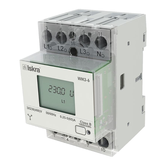
CONNECTION 2.2 Electrical connection WARNING Wrong or incomplete connection of voltage or other terminals can cause non-operation or damage to the device. Meter is used for direct connection into the four-wire networks. Meter can be equipped with different modules. Pictures below are showing equipped combinations. Recommended installation: Mounting to DIN rail according to DIN EN60715 Power contacts:... - Page 13 CONNECTION Figure 4: Connection diagram for M-BUS option Figure 5: Connection diagram for pulse output option Figure 6: Connection diagram for tariff input option User’s Manual...
- Page 14 CONNECTION Figure 7: Connection diagram for RS485 Complete WM3x6 system is assembled with three main units and optionally communication unit: Individual phase measurement unit. Power supply unit (based on configuration). Processing unit (MCU) with IR communication, LED indicator, LCD support and EEPROM. ...
- Page 15 CONNECTION Auxiliary terminal M-Bus Table Survey Pulse output communication Tariff input connection RS485* *It is recommended to use ferrite bead on communication line RS485 (two turns) to reduce radiated emission. PLEASE NOTE Check labels on the side of the meter to check what modules are built in. Auxiliary terminal Digital input L (switch)
- Page 16 FIRST STEPS 3 FIRST STEPS Programming a three-phase electrical energy meter WM3x6 is very transparent and user friendly. Numerous settings are organized in groups according to their functionality. In this chapter you will find basic programming steps: NDIVIDUAL PHASE MEASUREMENT UNIT ISPLAY OF DEVICE INFO OFTWARE FUNCTIONS LCD U...
-
Page 17: I Ndividual Phase Measurement Unit
FIRST STEPS 3.1 Individual phase measurement unit The microprocessor is used to process the voltage and current samples from the AD converter. It calculates the RMS voltage, RMS current, active and reactive power, U-I phase angle, first harmonic of voltage, first harmonic of current, the DC voltage, DC current, peak to peak voltage, peak to peak current, THD of voltage and THD of current. -
Page 18: D Isplay Of Device Info
FIRST STEPS For MID approved meters only active energy is approved – non resettable counters. The approved active energy counters are coded with the following codes: 1110 – Import Active Power, Tariff 1 1120 – Import Active Power, Tariff 2 1130 –... -
Page 19: S Oftware Functions
MID meters). Password Level 2 – enables all available settings and resets. If meter password is forgotten, device serial number should be sent to Iskra, d.d. to receive device default password. WM3-6 supports MODBUS protocol. RTU mode is used. RTU messages start and end with a silent interval of at least 3,5 character times (t1-t2-t3-t4 as shown below). -
Page 20: Lcd U Ser I Nterface
FIRST STEPS 3.4 LCD User Interface The LCD display allows displaying the following measurement values: Four Energy registers: Energy counter 1 (mandatory) Energy counter 2 III. Energy counter 3 IV. Energy counter 4 Actual measured values: Active Power, total, ph1, ph2, ph3 Reactive Power, total, ph1, ph2, ph3 III. - Page 21 FIRST STEPS Energy counters are represented as shown on LCD examples bellow: Non-MID meters show resettable counters (letter r representing it) MID meters show non resettable counters (letters nr representing it) Counter 1 shows: Import Active Energy = 6250.3 kWh at Tarif 2 Counter 2 shows: Export Active Energy = 70352.5 kWh at Tarif 1 Counter 3 shows: Total Active Energy = 2369025.3 kWh at both Tarif 1 and 2 Counter 4 shows: Total Active Energy = 105101.5 kWh at Tarif 1...
- Page 22 FIRST STEPS Phase Voltages: Voltage ph. 3 Voltage ph. 2 Voltage ph. 1 Phase to phase Voltages: Volt. ph to ph U12 Volt. ph to ph U23 Volt. ph to ph U13 Reactive powers: Reactive pow. total Reactive pow. ph 1 Reactive pow.
- Page 23 FIRST STEPS 3.4.2 Display menu structure The display menu is entered by holding the push button for more than one second. Blinking of the screen indicates that. Short clicks then move user through the main menu. By holding the button when positioned on certain screen ( e.g. measure, set, etc…) the sub-menu is entered. User’s Manual...
- Page 24 FIRST STEPS 3.4.2.1 Measure sub-menu When in measure sub-menu, short clicks move user through it, allowing her/him to select a dedicated menu. User’s Manual...
- Page 25 FIRST STEPS 3.4.2.1.1 Counter menu Holding button on any of screens 2.1.1 through 2.1.8 sets this screen as a meter screen. In the Counter menu all counters (resettable and non resettable) are displayed for both – MID and non MID meters 3.4.2.1.2 Power menu Holding button on any of screens 2.2.1 through 2.2.4 sets this screen as a meter screen.
- Page 26 FIRST STEPS 3.4.2.1.5 Reactive and apparent power menu Holding button on any of screens 2.5.1 through 2.5.8 sets this screen as a meter screen. 3.4.2.1.6 Power factor, power angle and frequency menu Holding button on any of screens 2.6.1 through 2.6.6 sets this screen as a meter screen. User’s Manual...
- Page 27 FIRST STEPS 3.4.2.2 Set sub-menu When in set sub-menu, short clicks move user through it, allowing her/him to select a dedicated menu. The screens 3.2 to 3.4 appear only in case the actual option is available on the meter. User’s Manual...
- Page 28 FIRST STEPS 3.4.2.2.1 Reset counters menu Holding button on any of screens 3.1.1 through 3.1.5 resets any of counters or all of them respectively. 3.4.2.2.2 RS485 menu Screen 3.2.1 shows the address of RS 485 communication and screen 3.2.2 shows the baud rate. 3.4.2.2.3 M-bus menu Screens 3.3.1 shows the primary address of M-bus communication, screen 3.3.2 shows baud rate and screen 3.3.3 shows the secondary address.
- Page 29 FIRST STEPS 3.4.2.4 Info sub-menu When in info sub-menu, short clicks move user through it, allowing her/him to get required information about smart meter. Screen 4.1 shows the serial number of the smart meter. Screen 4.2 shows the software version present on smart meter. Screen 4.3 shows CRC code and below the number of Firmware upgrades.
-
Page 30: Limit
FIRST STEPS 3.4.3 Set device ModBus address Non configured devices have the same factory Modbus address set to 33. One of the options for changing the Modbus address is the following. Holding the button for more than 6 seconds, the energy meter will switch to Modbus address configuration mode (you will see the screen below). - Page 31 FIRST STEPS 3.5.1 Limit A User can set the ON state of an output A, when the threshold is reached (any from the above specified measured values can be set as a threshold). Likewise the OFF state can be set, when the same measured value falls below the OFF state threshold.
- Page 32 FIRST STEPS Limit A AND Limit B Limit A AND Limit B is a logical operation, which sets the output A AND B ON, when both output A and output B are in ON. Figure below (example 3) shows the example of output A AND B being ON. For clearer picture refer also to output A (example 1) and output B (example 2) figures.
- Page 33 FIRST STEPS Following Modbus registers define Limit function: Address Contents Data Values P. Level LIMIT 40187 Limits enabled None Limit 1 Limit 2 Limit 1 OR Limit 2 Limit 1 AND Limit 2 40188 Display notification None Relay ON Relay OFF 40189 Limit 1: Parameter See OutTypes...
- Page 34 FIRST STEPS Power Factor Phase 3 (PF3) PA angle between U and I 100° j1 (angle between U1 and I1) j2 (angle between U2 and I2) j3 (angle between U3 and I3) fi U12 j12 (angle between U1 and U2) 100°...
-
Page 35: F Reeze Counters
FIRST STEPS 3.6 Freeze counters 3.6.1 Meaning Since WM3-6 energy meter does not support internaly synchronised real-time clock (RTC) for the purpose of simultaneous capture of measurements, the freeze function is implemented. Use is enabled only when the meter is on. Freeze function enables using WM3x6 smart meters for billing or sub-billing purposes and to compare sub-metering data with main energy meter. - Page 36 FIRST STEPS 3.6.5 Status register of freeze (41905) The purpose of the status register is to test the reliability of RS485 communication. Enter the broadcast command of different identification codes between 1 to FFFD in the freeze status register (41905). Repeatedly send a different identification code to the freeze status register (41905) in order to increase the reliability of receiving commands.
- Page 37 SETTINGS 4 SETTINGS A setting structure, which is similar to a file structure in an explorer is displayed in the left part of the MiQen setting window. Available settings of that segment are displayed in the right part by clicking any of the stated parameters.
-
Page 38: Introduction
(size 1 DIN module) and MiQen software version 2.0 or higher. 4.2 MiQen software MiQen software is a tool for a complete programming and monitoring of ISKRA measuring instruments, connected to a PC via serial communication or by a special WM-USB adapter. A user-friendly interface consists of five segments: devices management (Connection), instrument settings (Settings), real-time measurements (Measurements), data analysis (Analysis), and software upgrading (Upgrades). - Page 39 SETTINGS MiQen version 2.1 or higher is required for programming and monitoring WM3x6. Software installation is stored on a CD as a part of consignment or it can be downloaded from https://www.iskra.eu/en/Iskra- Software/MiQen-Settings-Studio/ PLEASE NOTE MiQen has very intuitive help system. All functions and settings are described in Info window on the bottom of MiQen window.
- Page 40 SETTINGS Set device Modbus address number Each device connected to a network has its unique Modbus address number. In order co communicate with that device an appropriate address number should be set. Factory default Modbus address for all devices is 33. Therefore it is required to change Modbus address number of devices if they are connected in the network so each device will have its unique address number.
- Page 41 The BP password is available in the user support department in ISKRA d.d., and is entered instead of the password PL1 or/and PL2. Do not forget to state the device serial number when contacting the personnel in ISKRA, d.d.
- Page 42 SETTINGS 4.2.2.2.1 Counters Changing counter settings is allowed only on NonMID meters. There are four pairs of counters, which are user configurable. Each counter setting applies to one resetable and one non-resetable counter. User can set Active, Reactive, Apparent Energy, energy flow direction and tariff.
- Page 43 SETTINGS Figure 15: Measurements in tabular form Figure 16: Measurements in graphical form For further processing of the results of measurements, it is possible to set a recorder ( button) on active device that will record and save selected measurements to MS Excel .csv file format. Figure 17: Measurements Recorder User’s Manual...
- Page 44 SETTINGS 4.2.4 DATA ANALYSIS PLEASE NOTE The energy meter WM3x6 do not support data analysis. 4.2.5 MY DEVICES My devices section enables the personal selection of devices. 4.2.6 Software upgrading MID version does not support software upgrade. Always use the latest version of software, both MiQen and software in the device. The program automatically informs you about available upgrades (device firmware upgrades and MiQen software upgrades) that can be transferred from the web site and used for upgrading.
-
Page 45: Table Of Contents
TECHNICAL DATA 5 TECHNICAL DATA In following chapter all technical data regarding operation of a three-phase electrical energy meter is presented. CCURACY ECHANICAL CHARACTERISTICS OF INPUT LECTRICAL CHARACTERISTICS OF INPUT AFETY AND AMBIENT CONDITIONS User’s Manual... -
Page 46: Technical Data
TECHNICAL DATA 5.1 Accuracy Measured values Accuracy class Active energy: class 1 EN 62053-21 class B EN 50470-3 ±1.5% from �� to �� ������ ���� ±1% from �� to �� ���� ������ Reactive energy: class 2 EN 62053-23 ±2.5% from �� to ��... -
Page 47: Mechanical Characteristics Of Input
TECHNICAL DATA 5.2 Mechanical characteristics of input Rail mounting according DIN EN 60715. Terminals Max. conductor cross-sections 2.5 ���� ... 25 (16) ���� Main inputs Contacts capacity: Connection screws: Max torque: 3.5 Nm (PZ2) 10 mm Length of removed isolation: Optional modules Contacts capacity: 1 mm... - Page 48 TECHNICAL DATA Pulse output (option) Pulse rate: 1000 imp/kWh Pulse duration: 32 ± 2 ms Rated voltage DC: 27 V max Switched current 27 mA max Standard: EN 62053-31 (A&B) M-BUS Serial communication (option) Type: M-BUS Speed: 300 bit/s to 9600 bit/s (default 2400 bit/s) Protocol: M-BUS Primary address:...
-
Page 49: Safety And Ambient Conditions
TECHNICAL DATA 5.4 Safety and ambient conditions According to standards for indoor active energy meters. Temperature and climatic condition according to EN 62052-11. Dust/water protection: IP50 (For IP51 it should be installed in appropriate cabinet.) Operating temperature: -25 °C - +55 °C (non-condensig humudity) Storage temperature: -40 °C - + 70 °C Enclosure:... -
Page 50: Eu Directives Conformity
TECHNICAL DATA 5.5 EU DIRECTIVES CONFORMITY 5.5.1 WM3M6 MID certified meters MID approval applies to non-resettable active energy counters. EU Directive on Measuring Instruments 2014/32/EU EU Directive on EMC 2014/30/EU EU Directive on Low Voltage 2014/35/EU EU Directive WEEE 2002/96/EC EU RED Directive 2014/53/EU 5.6 Dimensions 5.6.1 Dimensional drawing... - Page 51 Abbreviations are explained within the text where they appear the first time. Most common abbreviations and expressions are explained in the following table: Term Explanation MODBUS / DNP3 Industrial protocol for data transmission MiQen Setting Software for ISKRA instruments Pulse input module Alternating quantity Infrared (optical) communication Pt1000 Temperature sensor Root Mean Square...
-
Page 52: Appendix A: Modbus Communication Protocol
APPENDICES 7 APPENDICES 7.1 APPENDIX A: MODBUS communication protocol Modbus protocol enables operation of device on Modbus networks. For WM3-6\WM3M6 with serial communication the Modbus protocol enables multi drop communication via RS485 communication. Modbus protocol is a widely supported open interconnect originally designed by Modicon. - Page 53 APPENDICES Request Frame Starting Register Register Count Slave Address Function Code Response Frame Register Data Slave Address Function Code Byte Count HI LO HI LO FE 00 59 96 Request- response cycle example Address number of slave: 21 Function code: 04 30000 ...
- Page 54 APPENDICES Contents Data Values / Dependencies Address Input Registers 30080 FW upgrade counter 30090 phase module 0 CheckSum 30091 phase module 1 CheckSum 30092 phase module 2 CheckSum 30093 phase module 0 SW reference 100=1,0 30094 phase module 1 SW reference 100=1,0 30095 phase module 2 SW reference...
- Page 55 APPENDICES Contents Data Values / Dependencies Address Input Registers ACTUAL MEASUREMENTS 30105 30106 Frequency 30107 30108 30109 30110 30111 30112 30115 angle between U1 and U2 30116 angle between U2 and U3 30117 angle between U3 and U1 30126 30127 30128 30129 30130...
- Page 56 APPENDICES 30174 angle between U2 and I2 30175 angle between U3 and I3 30182 U1 THD% 30183 U2 THD% 30184 U3 THD% 30188 I1 THD% 30189 I2 THD% 30190 I3 THD% 30197 External relay status Comm. Error Not connected 30198 Load control output status 30199 Digital input status...
- Page 57 APPENDICES Contents Data Values / Dependencies Address Input Registers ENERGY 30400 Error register No Error Bit 0 Error Parameter CRC Bit 1 Error Firmware CRC Bit 2 MID version is not locked 30401 Energy Counter 1 Exponent (resettable) 30402 Energy Counter 2 Exponent (resettable) 30403 Energy Counter 3 Exponent (resettable) 30404...
- Page 58 APPENDICES Address Data Values Contents Level RAM logger 36000 Measurement parameter See OutTypes 36001 Time interval minutes 36002 Number of valid results 36003 Time stamp of last minutes since midnight result (<0 if no time) 36004 36131 Logger table (newest to Normalised values oldest) ACTUAL MEASUREMENTS...
- Page 59 APPENDICES Address Contents Data Values Level 40013 Reset command register 1 Bit-0 Reset counter 1 Bit-1 Reset counter 2 Bit-2 Reset counter 3 Bit-3 Reset counter 4 Reset alarm output relay Bit-4 40015 external relay command action 40016 Load control Output state 40017...
- Page 60 APPENDICES Address Data Values Contents Level Reverse Energy flow 40151 CT connection direction (Fixed) 40173 LCD Mode Manual Cycling 40174 LCD cycling period Seconds 40183 WM3 - LCD parameters Bit 0 Active Power P1 65535 Bit 1 Active Power P2 Bit 2 Active Power P3 Bit 3...
- Page 61 APPENDICES Manual 40187 Limits enabled None Limit 1 Limit 2 Limit 1 OR Limit 2 Limit 1 AND Limit 2 40188 Display notification None Relay ON Relay OFF Address Contents Data Values Level LIMIT 40189 Limit 1: Parameter See OutTypes 40190 Limit 1: Compare relation measurement >...
- Page 62 APPENDICES Address Contents Data Values Level ENERGY 40401 Active Tariff Tariff input 1..2 Tariff 1..2 40421 Energy Counter Active Power Parameter Reactive Power Apparent Power 40422 Energy Counter Bit-0 Quadrant I Enabled Configuration Bit-1 Quadrant II Enabled Bit-2 Quadrant III Enabled Bit-3 Quadrant IIII Enabled Bit-4...
- Page 63 APPENDICES Counter freeze 41901 Auto freeze interval [minutes] 41902 time to freeze [s] 41903 41904 time from freeze [s] 41905 Freeze status 41906 Current Active Tariff 41907 41908 Energy Counter 1 (resetable) 41909 41910 Energy Counter 2 (resetable) 41911 41912 Energy Counter 3 (resetable) 41913 41914...
- Page 64 APPENDICES Type Value / Bit Mask Description Unsigned Measurement (32 bit) bits # 31..24 Decade Exponent(Signed 8 bit) bits # 23..00 Binary Unsigned Value (24 bit) Example: 123456*10 stored as FD01 E240 (16) Signed Measurement (32 bit) bits # 31..24 Decade Exponent (Signed 8 bit) bits # 23..00 Binary Signed value (24 bit)
- Page 65 APPENDICES Type Value / Bit Mask Description T_Time Time and Date (64 bit) bits # 63..56 1/100s 00 - 99 (BCD) bits # 55..48 Seconds 00 - 59 (BCD) bits # 47..40 Minutes 00 - 59 (BCD) bits # 39..32 Hours 00 - 24 (BCD) bits # 31..24 Day of month 01 - 31 (BCD)
-
Page 66: Appendix B: M-Bus
Secondary Address (UD) consists of: Identification Number: 00000000 – 99999999 8-digit Secondary Address number Manufacturer’s Code: 73 26 2 Byte Company Constant (Iskra = “73 26”) Version Number: 01 – FF 1 Byte Medium: 02 1 Byte Constant Electricit Reset, Restart M-BUS MC350 via Primary/Secondary Address (SND_UD) This Telegram reset/restarts M-BUS MC350. - Page 67 APPENDICES M-Bus Telegram Total Energy counters 0, 1, 2, 3 Energy counters could represent: +/- active energy, +/-reactive energy or apparent energy and one of 4-th tariff. DIFE DIFE VIFE VIFE VIFE DATA xx.xx.xx.xx none none none none None none none none none...
- Page 68 APPENDICES Active Power in Phase 1, 2, 3 (W) Active power in 32bit x 10 (2-3) DIFE DIFE VIFE VIFE DATA xx.xx.xx.xx Current in Phase 1, 2, 3, Neutral (A) Phase current as 32 bit x 10 (9-12) DIFE VIFE VIFE VIFE DATA...
- Page 69 • Published by Iskra, d. d. • Subject to change without notice • Version 1.01 November 2018 • EN K 22.433.920...
Need help?
Do you have a question about the WM3x6 Series and is the answer not in the manual?
Questions and answers