Table of Contents
Advertisement
Available languages
Available languages
Quick Links
ANLEITUNG FÜR EINBAU, BEDIENUNG UND WARTUNG
KESSEL Fettabscheider EasyClean free
Mix, Auto Mix, Mix & Pump, Auto Mix & Pump
in NS 2, 3, 4, 7, 10
zur Aufstellung in frostfreien Räumen
o Installation
o Inbetriebnahme
der Anlage wurde durchgeführt von Ihrem Fachbetrieb:
Name/Unterschrift
Stand 2018/02
o Einweisung
Datum
Produktvorteile
Ort
Stempel Fachbetrieb
D
GB Page 63
Leichte Einbringung
Einfach bedienbar
Einfache Änderung der
Fließrichtung vor Ort
Zulassungsnummer
Z-54.1-474
Automatische Spülung der
Trinkwasserleitungen
Sach-Nr. 010-917DE_EN
Seite 1
Advertisement
Chapters
Table of Contents

Related Manuals for Kessel EasyClean free Mix


Summary of Contents for Kessel EasyClean free Mix
- Page 1 ANLEITUNG FÜR EINBAU, BEDIENUNG UND WARTUNG KESSEL Fettabscheider EasyClean free Seite 1 GB Page 63 Mix, Auto Mix, Mix & Pump, Auto Mix & Pump in NS 2, 3, 4, 7, 10 zur Aufstellung in frostfreien Räumen Produktvorteile Leichte Einbringung Einfach bedienbar Einfache Änderung der...
-
Page 2: Table Of Contents
Einleitung Produktbeschreibung, allgemein ..................4 Anlagentypen C D E F ...................... 4 Typenschild ........................5 Lieferumfang ........................6 Allgemeine Hinweise zu dieser Betriebs- und Wartungsanleitung ........6 Baugruppen und Funktionsmerkmale ................7 1.6.1 Schaltgerät ........................9 Sicherheit Bestimmungsgemäße Verwendung .................. 11 2.2 Personalauswahl und -qualifikation .................. - Page 3 3.4.3 Schaltgerät für Anlagentyp F .................... 29 Erstbefüllung und Druckprüfung ..................32 3.5.1 Funktionskontrolle Anlagentyp C ..................32 3.5.2 Funktionskontrolle Anlagentyp D ..................33 3.5.3 Funktionskontrolle Anlagentyp E ..................34 3.5.4 Funktionskontrolle Anlagentyp F ..................34 Betrieb Einschalten Anlagentyp C ....................36 Einschalten Anlagentyp D ....................
-
Page 4: Einleitung
Sichtkontrolle des im Anlagenbehälter angesammelten Fettes. Anlagentypen C D E F Die Fettabscheideranlage wird in diesen Ausführungen hergestellt: Anlagenbezeichnung EasyClean free Mix EasyClean free Auto Mix „Auto Mix“ EasyClean free Mix & Pump „Mix & Pump“ EasyClean free Auto Mix & Pump „Auto Mix & Pump“ * Optional... -
Page 5: Typenschild
Einleitung Typenschild Informationen auf dem Typenschild der Fettabscheideranlage 10 Revisionsstand der Hardware 52 Materialbezeichnung 53 Materialnummer 55 Norm Bahnhofstraße 31 D-85101 Lenting 56 Freitext / Erklärung 57 Freitext / Erklärung 58 Freitext / Erklärung 59 Freitext / Erklärung Made in Germany 75 Freitext / Erklärung Werkstoff Abb. -
Page 6: Lieferumfang
Einleitung Lieferumfang – Fettabscheideranlage (siehe 1.6) – Betriebs- und Wartungsanleitung Allgemeine Hinweise zu dieser Betriebs- und Wartungsanleitung Verwendete Symbole und Legenden <1> Hinweis im Text auf eine Legendennummer in einer Abbildung Bezug auf eine Abbildung • Arbeitsschritt Arbeitsschritt in nummerierter Reihenfolge –... -
Page 7: Baugruppen Und Funktionsmerkmale
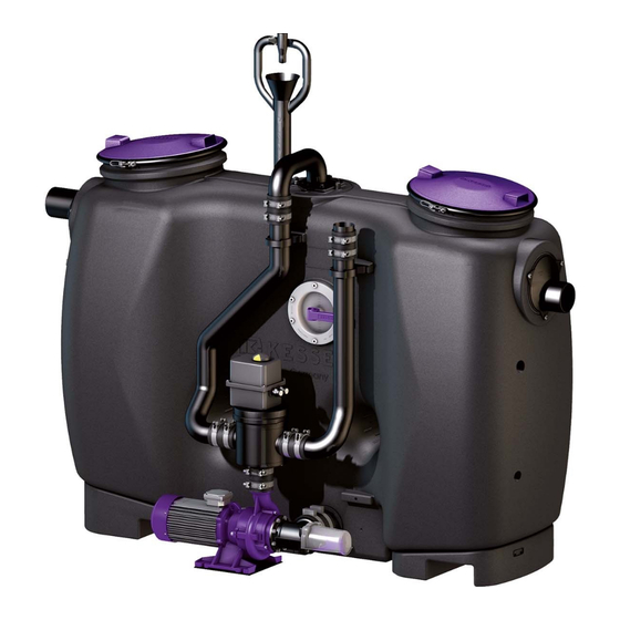
Einleitung Baugruppen und Funktionsmerkmale Abbildung zeigt Anlagentyp F Abb. [3] 11 Schauglas 13 Typenschild 16 Zulauf* 17 Fülleinrichtung 18 Direktentleerungsrohr 22 Druckrohr 24 Pumpe (Reinigen und Schreddern) 26 Umschaltventil 27 Stellmotor Umschaltventil (Anlagentyp F) 28 Schaltgerät (Anlagentyp D E F) 30 Revisionsdeckel 35 Ablauf* * Zu- und Ablauf können gegenseitig getauscht werden... - Page 8 Einleitung Abbildungen der Anlagentypen (C D E) Abb. [4] 010-917DE_EN 8 / 124 2018/02...
-
Page 9: Schaltgerät
Einleitung 1.6.1 Schaltgerät 1.6.1.1 Schaltgerät „Mix & Pump“ für Anlagentyp E Fettabscheider/Greas Seperator “M“ Betriebsbereit Alarm LED Start / Stop Entleerungsbetrieb Start / Stop Alarm Quittierung des akustischen Alarms Pumpenlauf-LED Abb. [5] 1.6.1.2 Schaltgerät „Auto Mix & Pump“ für Anlagentyp F C D E Allgemeines Die Menüsteuerung verfügt über einen Bedien- und einen Standbymodus. Erfolgt über einen Zeitraum von ca. - Page 10 Einleitung Displayanzeige Nummer des Menüs Name des Menüs Abb. [7] 010-917DE_EN 10 / 124 2018/02...
-
Page 11: Sicherheit
– Verwendungen von nicht originalen Ersatzteilen – Durchführungen von Reparaturen durch nicht vom Hersteller autorisierte Betriebe oder Personen können zum Verlust der Gewährleistung führen. Nachträgliche Erweiterungen von Kessel- Fettabscheideranlagen EasyClean free müssen durch den Kessel- Werkskundendienst abgewickelt werden. Personalauswahl und -qualifikation Personen, die Fettabscheideranlagen bedienen und/oder montieren, müssen –... -
Page 12: Gefahren, Die Vom Produkt Ausgehen
Sicherheit Gefahren, die vom Produkt ausgehen 2.4.1 Gefahr durch elektrischen Strom und Kabel Alle spannungsführenden Bauteile sind gegen unbeabsichtigte Berührung sowie Spritzwasser aus allen Richtungen (IP 54) geschützt. Vor einem Öffnen von Gehäuseabdeckungen, Steckern und Kabeln sind diese spannungsfrei zu machen. Arbeiten an elektrischen Bauteilen dürfen nur von Fachpersonal (Siehe 2.2) durchgeführt werden. -
Page 13: Montage
Montage Montage Empfehlungen zum Aufstellort / Betrieb – Raum mit guter Belüftung oder/und Ventilation sowie ebener und ausreichend tragfähiger Aufstellfläche. – Raumtemperatur mindestens 15° C. – Abgedichteter Bodenbelag mit integrierter Ablaufstelle. – Warm- und Kaltwasseranschluss – Raumhöhe mindestens 60 cm höher als die Fettabscheideranlage, damit bei Reinigungsarbeiten die Revisionsdeckel geöffnet werden können. –... -
Page 14: Fettabscheideranlage Aufstellen / Montieren
Die Bohrgeschwindigkeit* muss so gewählt werden, dass es nicht zu thermischen Verformungen der Schnittfläche kommt. *Empfehlung: 500m/s (Drehzahl Bohrglocke 1.300 U/min bei Ø 120 mm, Ø 120 mm = KESSEL-Art. Nr.:50101) Drehmomente für die Schraubverbindungen sind im Kapitel 7.2 gelistet. Sicherstellen, dass diese entsprechend berücksichtigt werden. -
Page 15: Schauglas Montieren
Montage 3.3.2 Schauglas montieren C D E F • Vertiefung <B> in der Aufnahme für das Schauglas mittels Bohrglocke (Ø 162 mm) ausbohren. • Schauglas <11> zusammen mit der Dichtung <56> mit den Schrauben <57> befestigen. Abb. [10] Bei einem Umbau Dichtung <56> einfetten. 3.3.3 Direktentleerungsrohr montieren - C D Zur optimalen Abdichtung die Bohrkanten nicht entgraten. -
Page 16: Pumpe Montieren
Montage 3.3.4 Pumpe montieren C D E F Zur optimalen Abdichtung die Bohrkanten nicht entgraten. • Bohrung <C> in der Anbohrfläche erstellen (Bohrglocke, Ø 118 mm). • Durchgangsdichtung <40> in das Bohrloch einsetzen. • Ansaugstutzen für Pumpe <21> in die Durchgangsdichtung hineinstecken. Abb. [12] • Pumpe <24>... -
Page 17: Mechanisches Zwei-Wege-Ventil Montieren - E
Montage 3.3.5 Mechanisches Zwei-Wege-Ventil montieren - E • Ventil <26> mit dem Verbindungsstück <38> und den Schellen <37> an der Pumpe befestigen. Abb. [14] 3.3.6 Elektrisches Zwei-Wege-Ventil montieren - F C D E • Ventil <26> mit dem Verbindungsstück <38> und den Schellen <37>... -
Page 18: Direktentleerungsrohr Montieren - E F
Montage 3.3.7 Direktentleerungsrohr montieren - E F • Befestigungsschelle <34> an der Aufnahme <A> am Anlagenbehälter mit der Schraube <42> montieren. • Direktentleerungsrohr <18> an der Befestigungsschelle <34> lose befestigen. • Direktentleerungsrohr <18> mit den Schellen <37> und dem Verbindungsstück <38> am Ventil befestigen. •... -
Page 19: Druckrohr Montieren - C D
Montage 3.3.8 Druckrohr montieren - C D Das Druckrohr ist je nach Ausführung 2- oder 3-teilig. Der Fettabscheider mit der Nenngröße 10 ist mit zwei oberen Druckrohren <36> ausgestattet (Y-Stück nach Verbindungsstück <38>). • Bohrung <C> in der Anbohrfläche erstellen (Bohrglocke, Ø 110 mm). • Befestigungsschelle <34> an der Aufnahme <A> am Anlagenbehälter mit der Schraube <42>... -
Page 20: Druckrohr Montieren - E F
Montage 3.3.9 Druckrohr montieren - E F Das Druckrohr ist je nach Ausführung 2- oder 3-teilig. Der Fettabscheider mit der Nenngröße 10 ist mit zwei Oberen Druckrohren <36> ausgestattet (Y-Stück nach Verbindungsstück <38>). • Kreisrunde Öffnung <C> am Abscheidebehälter mittels Bohrglocke (Ø 110 mm) erstellen. •... -
Page 21: Fülleinrichtung Montieren
Montage 3.3.10 Fülleinrichtung montieren C D E F Zur optimalen Abdichtung die Bohrkanten nicht entgraten. • Befestigungsschelle <34> an der Aufnahme <A> am Anlagenbehälter mit der Schraube <42> montieren. • Kreisrunde Öffnung <B> in der Aufnahme für die Fülleinrichtung ausschneiden (Bohrglocke, Ø 70 mm). 34 42 •... -
Page 22: Magnetventile Montieren - F
Montage 3.3.12 Magnetventile montieren - F C D E Das Ventil muss waagerecht montiert werden. • Magnetventile <51> wie abgebildet installieren und entsprechend an die Wasserleitungen (kalt / warm ) anschließen. • Schraubventile installieren und entsprechend an die Wasserleitungen (kalt / warm ) anschließen. - Page 23 Montage • Kabel des Sensors durch die Kabeldurchführung <58> führen. Sicherstellen, dass die Kabeldurchführung fachgerecht montiert und zugeschraubt ist. Für Wartungszwecke muss ca. 1 m Kabellänge vorgesehen werden, damit der Sensor aus dem Anlagenbehälter herausgehoben werden kann. • Falls die Fließrichtung geändert wird, muss auch SonicControl auf die Ablaufseite montiert werden.
-
Page 24: Fernbedienung Montieren - F
Montage 3.3.14 Fernbedienung montieren - F C D E Bediengerät Fernbedienung an gewünschter Position wie folgt montieren. • Schrauben <52> mit Dübeln <53> (oder geeigneten Befestigungsmaterialien) so montieren, dass die Fernbedienung <54> daran eingehängt werden kann. Im Lieferumfang ist eine Bohrschablone enthalten. Der elektrische Anschluss wird bei der Installation des Schaltgerätes beschrieben. - Page 25 Montage 3.4.1.2 Elektrische Anschlüsse herstellen • Anschlüsse gemäß Anschlussplan herstellen (nachstehend und im Gehäusedeckel des Schaltgerätes). Anschlussplan OFF ON 2 4 6 SICHERUNG SICHERUNG Fuse Fuse Fusible Fusible 230VAC 50Hz 230VAC 50Hz +12V +12V F1 315 mAT F2 5AM 1/gr/GY 2/bl/BU gnge/GNYE +12V...
- Page 26 Montage 3.4.1.3 Initialisierung des Schaltgeräts Ein Trockenlauf der Pumpe(n) ist unbedingt zu vermeiden. Taste nicht betätigen! Start / Stop • Stromversorgung Schaltgerät einschalten und Hauptschalter in Position ON bringen, im Display erscheint das Menü 3.8.1. Wird im Display nicht das Menü 3.8.1 (die Initialisierung) angeboten, wurde das Schaltgerät bereits initialisiert. In diesem Fall sind die eingestellten Parameter (gemäß...
-
Page 27: Schaltgerät Für Anlagentyp E
Montage 3.4.2 Schaltgerät für Anlagentyp E 3.4.2.1 Montage des Schaltgeräts „Mix & Pump“ • Montageort für das Schaltgerät „Mix & Pump“ auswählen (Kabellänge Pumpe berücksichtigen). Achtung, Gefahr durch elektrischen Strom! Das Schaltgerät darf nur geöffnet werden, wenn der Netzanschluss getrennt ist. • Hauptschalter <23> in Position OFF bringen. • Schrauben <25> lösen. • Gehäuse aufklappen. •... - Page 28 Montage 3.4.2.2 Elektrische Anschlüsse herstellen • Anschlüsse gemäß Anschlussplan herstellen (nachstehend und im Gehäusedeckel des Schaltgerätes). Anschlussplan Abb. [30] Netz Pumpe Potentialfreier Kontakt Warnung / Alarm Fernbedienung (Bei Anschluss der Fernbedienung Brücke <e> entfernen) Kontrollleuchte Pumpe in Betrieb 010-917DE_EN 28 / 124 2018/02...
-
Page 29: Schaltgerät Für Anlagentyp F
Montage Montage 3.4.2.3 Initialisierung des Schaltgeräts Ein Trockenlauf der Pumpe(n) ist unbedingt zu vermeiden. Tast nicht betätigen! Start / Stop • Nenngröße (NS) gemäß Angabe auf dem Typenschild einstellen, dazu die DIP-Schalter (rechts oberen auf der Platine) wie folgt einstellen: NS 2 NS 3 NS 4... - Page 30 Montage 3.4.3.2 Elektrische Anschlüsse herstellen • Anschlüsse gemäß Anschlussplan herstellen (nachstehend und im Gehäusedeckel des Schaltgerätes). OFF ON 2 4 6 SICHERUNG SICHERUNG Fuse Fuse Fusible Fusible 6/ws/WH 230V AC 50Hz 230V AC 50Hz 5/sw/BK +12V +12V F1 315 mAT F2 5AM 4/bl/BU 1/gr/GY...
- Page 31 Menü Norm. Der Termin für die Entleerung wir ebenfalls angezeigt und ist automatisch gespeichert (ändern siehe 6.3, Menü 2.4). SonicControl Sensor Ist ein SonicControl (Option) angeschlossen, Frage mit „ja“ beantworten, sonst weiter mit „nein“, das Menü Norm wird angezeigt. Wenn „ja“: • Passworteingabe (muss bei KESSEL bezogen werden). • Anlagenart aus der Displayauswahl auswählen und mit OK übernehmen, es wird das Menü Norm angezeigt. Norm •...
-
Page 32: Erstbefüllung Und Druckprüfung
Montage Anzahl Pumpen • Anzahl Pumpen / Leistungsgröße (Siehe Typenschild der Pumpe(n)) auswählen und OK betätigen. Die Initialisierung ist abgeschlossen und im Display wird das Menü mit den soeben durchgeführten Systeminfo Einstellungen angezeigt. • Kalibrierung SonicControl • Kalibrierung des SonicControl Sensors. •... -
Page 33: Funktionskontrolle Anlagentyp D
Montage 3.5.2 Funktionskontrolle Anlagentyp D Funktion Pumpe prüfen • Schaltgerät „Auto Mix“ einschalten, Menü 0, Systeminfo wird angezeigt. • Taste OK betätigen, Menü wird angezeigt. • => auswählen, die Wartung Handbetrieb => Reinigen+Schreddern Pumpe wird eingeschaltet. • Mittels Sichtkontrolle durch das Schauglas sicherstellen, dass durch das Druckrohr <22> Wasser in den Anlagenbehälter gepumpt wird. •... -
Page 34: Funktionskontrolle Anlagentyp E
Montage 3.5.3 Funktionskontrolle Anlagentyp E • Schaltgerät „Mix & Pump“ einschalten. Sicherstellen, dass sich das Umschaltventil nicht in Position „Entsorgen“ befindet, der Inhalt des Anlagen- behälter würde abgepumpt werden. • Umschaltventil <26> auf Position Reinigen und Schreddern einstellen (Griff nach Rechts). • Taste Start / Stop betätigen, die Pumpe beginnt zu laufen. •... - Page 35 Montage Funktion Stellmotor Umschaltventil prüfen Im Menü wie folgt einstellen: Wartung • => Teilleeren, der Stellmotor bewegt das Ventil in die passende Position, anschließend läuft die Handbetrieb Pumpe an. Läuft die Pumpe sofort an, befand sich das Ventil bereits in der vorgesehenen Position. •...
-
Page 36: Betrieb
Betrieb Betrieb Der Fettabscheider separiert Fette, Öle und Schlamm aus dem Abwasser. Für die Entleerung der separierten Stoffe kommen je nach Anlagentyp unterschiedliche Verfahren und / oder Schaltgeräte zum Einsatz (Siehe 1.2). Einschalten Anlagentyp C D E F Der Fettabscheider ist nach erfolgreicher Funktionskontrolle (siehe 3.5.1) betriebsbereit. Einschalten Anlagentyp D Nach erfolgreicher Funktionskontrolle (siehe 3.5.2) kann die Fettabscheideranlage eingeschaltet werden, dazu:... -
Page 37: Einschalten Anlagentyp E
Betrieb Einschalten Anlagentyp E Nach erfolgreicher Funktionskontrolle (siehe 3.5.3) kann die Fettabscheideranlage eingeschaltet werden, dazu: • Hauptschalter einschalten*. Nach erfolgreichem Systemtest leuchtet die grüne LED <64>, die Fettabscheideranlage ist betriebsbereit. * Das Einschalten des Hauptschalters ist nur zur Entleerung notwendig. Abb. -
Page 38: Entleerung Durchführen
Entleerung durchführen Entleerung durchführen Allgemeines Die Entleerungszyklen der verschiedenen Anlagentypen sind darauf abgestimmt bei mittlerem Verschmutzungsgrad des Abwassers den Anlagenbehälter bei gleichzeitig bestmöglicher Reinigung vollständig zu entleeren. Ein Trockenlaufen der Pumpe ist bauartbedingt ausgeschlossen (Ausnahme: Erst- oder Wiederinbetriebnahme). Anlagentyp D und F Die Laufzeiten der Pumpe (Abpumpen + Schreddern) basieren ebenso wie die zugeführten Reinigen und... -
Page 39: Entleerung Anlagentyp C
Entleerung durchführen Entleerung Anlagentyp C D E F Ablaufschema Entleerungszyklus (Euro Norm 1825) Entleerungszeitraum Entleerungsfahrzeug pumpt ab Pumpe läuft (Reinigen und Schreddern) Zulauf Warmwasser* Zulauf Kaltwasser Zeitraum, bis Pegelstand ca. 10 cm abgesenkt wurde * empfohlen Abb. [39] Entleerung durchführen •... -
Page 40: Entleerung Anlagentyp D
Entleerung durchführen Entleerung Anlagentyp D Ablaufschema Entleerungszyklus (Euro Norm 1825) Einstellung im Menü Entleerungszeitraum A1 Automatikbetrieb (Reinigen und Schreddern, Teilfüllen) A2 Befüllen des Anlagenbehälters (Start durch Bediener) Entleerungsfahrzeug pumpt ab Pumpe läuft (Reinigen und Schreddern) 3.1.1 Ventil Teilfüllen (Zulauf Warmwasser*) 3.1.2 Ventil Füllen (Zulauf Kaltwasser, Start durch Bediener) 3.1.3... -
Page 41: Entleerung Anlagentyp E
Entleerung durchführen Entleerung Anlagentyp E Ablaufschema Entleerungszyklus (Euro Norm 1825) Entleerungszeitraum A1 Manueller Betrieb (Pumpenlaufzeiten) A2 Befüllen des Anlagenbehälters (durch Bediener) Entleerungsfahrzeug angeschlossen Pumpe läuft (Abpumpen, zum Entleerungsfahrzeug) Pumpe ein (Reinigen und Schreddern) Pumpe ein Umschalten des Ventils durch Bediener D1 Schaltposition Abpumpen D2 Schaltposition... - Page 42 Entleerung durchführen Entleerung durchführen • Schaltgerät einschalten. • Absaugschlauch des Entleerungsfahrzeugs an das Direktentleerungsrohr anschließen • der Entleerungsablauf <A1> ist aktiviert. Die Pumpe wird manuell ein- und Taste Start / Stop betätigen, ausgeschaltet. An den jeweiligen Schaltpunkten muss, je nach Anforderung des Entleerungszyklus (siehe Abb.
-
Page 43: Entleerung Anlagentyp F
Entleerung durchführen Entleerung Anlagentyp F C D E Ablaufschema Entleerungszyklus (Euro Norm 1825) Einstellung im Menü Entleerungszeitraum A1 Automatikbetrieb A2 Befüllen des Anlagenbehälters (Start durch Bediener) Entleerungsfahrzeug angeschlossen Pumpe läuft automatisch (Abpumpen, zum Entleerungsfahrzeug) 1.6.1. / -3 / -6 / -9 / -12 Pumpe ein (Reinigen und Schreddern) 1.6.2 / -5 / -8 / -11... - Page 44 Entleerung durchführen Entleerung im Automatikbetrieb durchführen (Die im Automatikbetrieb ablaufenden Schritte können einzeln über den Handbetrieb angesteuert werden) • Schaltgerät einschalten. • Schlauchverbindung zum Entleerungsfahrzeug an das Direktentleerungsrohr herstellen. • Taste Start / Stop betätigen, Menü wird angezeigt. Wartung • auswählen und OK drücken, Menü...
-
Page 45: Einstellungen, Bedienmenü
Einstellungen, Bedienmenü Einstellungen, Bedienmenü Anlagentyp D Schaltgerät „Auto Mix Allgemeine Hinweise und „Bedienmodus aktivieren“, siehe 6.3 Bedienmenü Systeminfo Informationen Betriebsstunden 1.1.1 Gesamtlaufzeit 1.1.2 Laufzeit Pumpe 1.1.3 Anläufe Pumpe 1.1.4 Netzausfall Logbuch 1.2.1 zuletzt aufgetretenes E&F* 1.2.2 davor aufgetretenes E&F 1.2.3 davor aufgetretenes E&F 1.2.4 …... - Page 46 Einstellungen, Bedienmenü Einstellungen Parameter 3.1.1 Reinigen+Schreddern 3.1.2 Ventil Teil-Füllen Einstellung in Absprache mit Werkskundendienst vornehmen 3.1.3 Ventil Füllen 3.1.4 Einschaltverzögerung 3.1.5 Intervall Legionellenspülung 3.1.6 Legionellenspülung kalt 3.1.7 Legionellenspülung warm 3.1.30 Zugriff RemoteControl Profilspeicher 3.2.1 Parameter speichern 3.2.2 Parameter laden Datum/Uhrzeit* Anzahl Pumpen* 3.4.1 1 Pumpe 4-6,4A...
-
Page 47: Anlagentyp E
Einstellungen, Bedienmenü Anlagentyp E Schaltgerät „Mix & Pump“ Einstellungen Siehe 3.4.2.3, Nenngrößen mittels Dippschalter einstellen. Anlagentyp F C D E Schaltgerät „Auto Mix & Pump“ Allgemeines Fettabscheider/Grease Seperator „PV+S“ Die Menüsteuerung verfügt über einen Bedien- und einen Stand-by- Modus. Im Bedienmodus können die System-Einstellungen durch das Bedienmenü... - Page 48 Einstellungen, Bedienmenü Bedienmenü Systeminfo Informationen Betriebsstunden 1.1.1 Gesamtlaufzeit 1.1.2 Laufzeit Pumpe 1.1.3 Anläufe Pumpe 1.1.4 Netzausfall 1.1.5 Laufzeit SonicControl 1.1.6 Betr. über Alarm-Niv. 1.1.7 Betr. über Alarm-Temp. 1.1.8 Anzahl der Entleerungen Logbuch 1.2.1 zuletzt aufgetretenes E&F 1.2.2 davor aufgetretenes E&F 1.2.3 davor aufgetretenes E&F 1.2.4...
- Page 49 Einstellungen, Bedienmenü 1.6.23 Messintervall 1.6.24 Niveau-Abgleich 1.6.30 Zugriff RemoteControl Messdaten 1.7.1 zuletzt ermittelte Schicht- Dicke und Temp 1.7.2 davor ermittelte Schicht- Dicke und Temp 1.7.3 davor ermittelte Schicht- Dicke und Temp 1.7.4 … Entleerung 1.8.1 letzte Entleerung Wartung Handbetrieb 2.1.1 Teil leeren 2.1.2 Mischen...
- Page 50 Einstellungen, Bedienmenü 3.1.9 Leeren 3.1.10 Füllen 3.1.11 Spülen 3.1.12 Leeren 3.1.13 Füllen 3.1.14 Reinigungsprogramm 3.1.15 Intervall Legionellenspülung 3.1.16 Legionellenspülung kalt 3.1.17 Legionellenspülung warm 3.1.18 Alarm-Schichtdicke 3.1.19 Voralarm-Schichtdicke 3.1.20 Alarm-Temperatur 3.1.21 Messbereichsanfang 3.1.22 Messbereichsende 3.1.23 Messintervall 3.1.24 Niveau-Abgleich 3.1.30 Zugriff RemoteControl Profilspeicher 3.2.1 Parameter speichern...
- Page 51 Einstellungen, Bedienmenü 3.7.9 Status Sprache* 3.8.1 Deutsch 3.8.2 English 3.8.3 Francais 3.8.4 Italiano 3.8.5 Nederlands 3.8.6 Polski Experten-Modus 3.9.1 Ein Verzögerung 3.9.2 Grenzlaufzeit 3.9.3 Leitfähigkeit 3.9.4 Dichte 3.9.5 Trigger 3.9.6 3.9.7 Rauschen 3.9.8 Alarm Sensor trocken 3.10 Rücksetzen 3.11 SonicControl* 3.12 Kalibrierung SonicControl 3.12.1...
-
Page 52: Technische Daten
Technische Daten Technische Daten Allgemeine technische Daten / Anschlusswerte Betriebsspannung 400 V AC 50 Hz Pumpe, Anschlusswert 400 V AC 50 Hz Pumpe, Gewicht ca. 27 kg Pumpenleistung 3,0 kW Leistung Stand-by (Schaltgerät) ca. 5 W Schutzart (Gesamtanlage) IP 54 Erforderliche Sicherung C 16A Bauseits nach VDE 0100... -
Page 53: Anschlussverbindungen
Technische Daten Anschlussverbindungen Fernbedienung LIYCY Klemmverbindung 100 m Nicht verlängern - Austausch 3x0,34 mm² Nicht verlängern - Austausch H05VV-F Fernbedienung Schukostecker 1,25 100 m durch NYM 3x1,5mm² oder 3x1,0mm² Ölflex Classic 110 SG* „Auto Mix & 40 m Montage mit NYM 5x2,5mm² nein Pump“ bei max. Länge (Abhängig von kein Kabel Gesamtanlage - Nennleistung) SG* „Mix & Pump“... -
Page 54: Maßzeichnung Und Gewichtstabelle
Technische Daten Maßzeichnung und Gewichtstabelle Abb. [45] zeigt Anlagentyp F NS 2 1500 1735 1055 1435 1765 200 l 400 l 100 l 600 l NS 3 1500 1735 1055 1435 1765 300 l 300 l 120 l 600 l NS 4 1880 2115... -
Page 55: Einstellungen (Entleerungszeiten)
Technische Daten Einstellungen (Entleerungszeiten) Spalte A: Entleerungsschritte Spalte B: Laufzeiten. (Bei Anlagenvariante F über Menü 3.1.1 bis 3.1.13 einstellbar) 2018/02 55 / 124 010-917DE_EN... -
Page 56: Wartung
Wartung Wartung Vor einem Öffnen von Gehäuseabdeckungen, Steckern und Kabeln sind diese spannungsfrei zu machen. Arbeiten an elektrischen Bauteilen dürfen nur von Fachpersonal (Siehe 2.2) durchgeführt werden. Wartungsintervalle Der Wartungstermin für die Fettabscheideranlage kann im Menü eingestellt 2. Wartung / 2.4 Wartungstermin werden. -
Page 57: Fehlersuche
Wartung Fehlersuche Störung Mögliche Ursache Maßnahme(n) Pumpenleistung Förderhöhe zu groß für die Leistung Die Pumpe der Fettabscheideranlage durch die Pumpe des bei der der Pumpe Entleerungsfahrzeug (absaugen) unterstützen Entleerung zu gering Kein oder wenig Raumtemperatur unter 15°C Länger beheizen, Raumtemperatur anheben Fett fließt ab Langsamer Aufbau einer festen Auch bei kalt fließenden Ölen regelmäßig beheizen... - Page 58 Wartung Temperaturfehler Wicklungstemperaturschalter hat Selbstrückstellend bei Motorabkühlung, ausgelöst Fehlermeldung mit Alarmtaste quittieren, bei weiteren Temperaturfehlermeldungen bitte Kundendienst kontaktieren Unterstrom Der minimale Strom der Pumpe Kabel prüfen und ggf. reparieren wurde unterschritten. (Das Kabel Pumpe tauschen falls defekt vom Schaltgerät zum Motor könnte unterbrochen oder beschädigt sein) Überstrom Der maximale Strom der Pumpe...
-
Page 59: Fettabscheider Reinigen
Wartung Relaisfehler Leistungsschütz schaltet nicht mehr Spannungsversorgung Schaltgerät ausschalten und Leistungsschütz durch Kundendienst austauschen lassen Permanente Geruchsbildung Störung Mögliche Ursache Maßnahme Geruchsbelästigung Abwasserleitungen undicht. Festsitz und Dichtungen kontrollieren, ggf. instand setzen Entlüftungsleitung fehlt, Querschnitt Bauseitig nachrüsten zu klein Geschlossener Raum ohne jeden Entlüftungsmöglichkeiten schaffen, zwangsgeführte Luftaustausch Entlüftung... -
Page 60: Anlagenpass / Werksabnahme
Anlagenpass / Werksabnahme Anlagenpass / Werksabnahme 010-917DE_EN 60 / 124 2018/02... -
Page 61: Generalinspektion / Wartungsanforderung
Generalinspektion / Wartungsanforderung Generalinspektion / Wartungsanforderung Der Betreiber einer Abscheideranlage ist nach den geltenden gesetzlichen Grundlagen, sowie nach DIN EN 1825 / DIN 4040-100 verpflichtet, die Anlage vor Inbetriebnahme, sowie wiederkehrend alle 5 Jahre einer Generalinspektion mit Dichtheitsprüfung zu unterziehen. Diese Prüfung darf nur von einer fachkundigen Person durchgeführt werden. Gerne bieten wir Ihnen die Generalinspektion durch einen unabhängigen Sachverständigen an. Wartungsanforderung Für Sie ist es wichtig, die Qualität und Funktionsfähigkeit Ihrer Anlage immer auf dem besten Stand zu halten, gerade wenn es um die Voraussetzung für eine Gewährleistung geht. - Page 62 Generalinspektion / Wartungsanforderung 010-917DE_EN 62 / 124 2018/02...
- Page 63 INSTRUCTIONS FOR INSTALLATION, OPERATION AND MAINTENANCE KESSEL Grease Separator EasyClean free Mix, Auto Mix, Mix & Pump, Auto Mix & Pump in NS 2, 3, 4, 7, 10 for set-up in frost-free rooms Product advantages Easy installation Easy operation Easy to convert flow...
- Page 64 Introduction Product description, general ..................... 66 System types C D E F....................... 66 Type plate ......................... 67 Scope of supply ........................ 68 General instructions on using these operating and maintenance instructions ....68 Component assemblies and functional properties ............69 1.6.1 Control unit ........................
- Page 65 3.4.3 Control unit for system type F ................... 90 Initial filling and pressure test ................... 93 3.5.1 Function check system type C ..................93 3.5.2 Function check system type D ..................94 3.5.3 Function check system type E ..................95 3.5.4 Function check system type F ..................
-
Page 66: Introduction
The grease separator system is made in these versions: System designation EasyClean free Mix EasyClean free Auto Mix “Auto Mix” EasyClean free Mix & Pump “Mix & Pump” EasyClean free Auto Mix & Pump “Auto Mix & Pump” * Optional... -
Page 67: Type Plate
Introduction Type plate Information on the grease separator system type plate 10 Hardware revision status 52 Material description 53 Material number 55 Standard Bahnhofstraße 31 D-85101 Lenting 56 Free text / explanation 57 Free text / explanation 58 Free text / explanation 59 Free text / explanation Made in Germany 75 Free text / explanation... -
Page 68: Scope Of Supply
Introduction Scope of supply – Grease separator system (see 1.6) – Operating and maintenance instructions General instructions on using these operating and maintenance instructions Symbols and keys used <1> Reference in the text to a legend number in an illustration Reference to an illustration •... -
Page 69: Component Assemblies And Functional Properties
Introduction Component assemblies and functional properties Illustration shows system type F Ill. [3] 11 Viewing window 13 Type plate 16 Inlet* 17 Filling device 18 Direct emptying pipe 22 Pressure pipe 24 Pump (cleaning and shredding) 26 Switchover valve 27 Actuator motor switchover valve (system type F) 28 Control unit (system type D E F) 30 Inspection cover 35 Outlet*... - Page 70 Introduction Illustrations of the system types (C D E) Ill. [4] 70 / 124 2018/02 010-917DE_EN...
-
Page 71: Control Unit
Introduction 1.6.1 Control unit 1.6.1.1 Control unit “Mix & Pump” for system type E Fettabscheider/Greas Seperator “M“ Ready for operation Alarm LED Start / Stop Emptying operation start / stop Alarm Acknowledgement of the acoustic alarm Pump run LED Ill. [5] 1.6.1.2 Control unit “Auto Mix &... - Page 72 Introduction Display Number of the menu Name of the menu Ill. [7] 72 / 124 2018/02 010-917DE_EN...
-
Page 73: Safety
Later extensions to the Kessel grease separator systems EasyClean free must be carried out by the Kessel factory customer services. -
Page 74: Risks Caused By The Product
Safety Risks caused by the product 2.4.1 Hazard through electrical current and cables All live components are protected against unintentional contact as well as splashwater from all directions (IP 54). Before housing covers, plugs and cables are opened, they must be made voltage-free. Work on electrical components may only be carried out by specialist staff (see 2.2). -
Page 75: Set-Up
Set-up Set-up Recommendations for the set-up location / operation – Well vented or ventilated room and one with level set-up area capable of bearing an appropriate load. – Room temperature at least 15°C. – Sealed floor covering with integrated drain. –... -
Page 76: Setting Up / Installing The Grease Separator System
*Recommendation: 500m/s (speed of drilling adapter 1,300 rpm with Ø 120 mm, Ø 120 mm = KESSEL-Art. no.50101) Torques for the screw connections are listed in chapter 7.2. -
Page 77: Fitting The Viewing Window
Set-up 3.3.2 Fitting the viewing window C D E F • Use a drilling adapter (Ø 162 mm) to drill out the recess<B> in the viewing window holder. • Fix the viewing window <11> and the seal <56> using the screws <57>. -
Page 78: Fitting The Pump
Set-up 3.3.4 Fitting the pump C D E F Do not deburr the drilling edges for optimum sealing. • Prepare drill hole <C> in the scored area (drilling adapter, Ø 118 mm). • Insert the all-round seal <40> into the drill hole. Insert the suction pipe joint for the pump <21>... -
Page 79: Fitting The Mechanical Two-Directional Valve - E
Set-up 3.3.5 Fitting the mechanical two-directional valve - E • Fix the valve <26> to the pump using the connection piece <38> and the clamps <37>. Ill. [14] 3.3.6 Fitting the electrical two-directional valve - F C D E • Fix the valve <26>... -
Page 80: Fitting The Direct Emptying Pipe - E F
Set-up 3.3.7 Fitting the direct emptying pipe - E F • Use the screw <42> to fit attachment clamp <34> to the seat <A> on the system tank. • Fix the direct emptying pipe <18> loosely to the attachment clamp <34>. •... -
Page 81: Fitting The Pressure Pipe - E F
Set-up • Use the clamps <37> and the connection piece <38> to fix the upper pressure pipe <36> to the lower pressure pipe <22> and fix to the system tank with the seal <59>. Ill. [18] 3.3.9 Fitting the pressure pipe - E F Depending on the version, the pressure pipe has 2 or 3 parts. -
Page 82: Fitting The Filling Device
Set-up • Use the clamps <37> and the connection piece <38> to fix the upper pressure pipe <36> to the lower pressure pipe <22> and fix to the system tank with the seal. Ill. [20] 3.3.10 Fitting the filling device C D E F Do not deburr the drilling edges for optimum sealing. -
Page 83: Fitting The Screw-Type Valve - E
Set-up 3.3.11 Fitting the screw-type valve - E The valve must be fitted horizontally. • Fit the screw-type valve(s) <50> into the water supply pipe(s). Ill. [22] 3.3.12 Fitting the solenoid valves - F C D E The valve must be fitted horizontally. •... -
Page 84: Fitting The Soniccontrol
Set-up Fitting the SonicControl 3.3.13 sensor (option) - F C D E • Open the inspection cover above the outlet fitting. • Use the screws <45> to fit the sensor holder <44> to the outlet fitting <43> as shown. • Fix the sensor <42>... -
Page 85: Fitting The Remote Control - F
Set-up 3.3.14 Fitting the remote control - F C D E Fit the remote control unit in the required position as follows. • Mount the screws <52> with dowel plugs <53> (or suitable attachment material) in such a way that the remote control <54> can be attached to them. - Page 86 Set-up 3.4.1.2 Setting up the electrical connections • Set up connections according to the wiring diagram (below and in the control unit housing cover). Wiring diagram OFF ON 2 4 6 SICHERUNG SICHERUNG Fuse Fuse Fusible Fusible 230VAC 50Hz 230VAC 50Hz +12V +12V F1 315 mAT...
- Page 87 Set-up 3.4.1.3 Initialising the control unit Care must always be taken that the pump(s) do(es) not run dry. Do not press the Start / Stop key. • Switch the control unit power supply on and put the main switch in the ON position, menu 3.8.1 appears in the display.
-
Page 88: Control Unit For System Type E
Set-up 3.4.2 Control unit for system type E 3.4.2.1 Installing the control unit “Mix & Pump” • Choose the installation location for the control unit “Mix & Pump” (taking pump cable length into consideration). Caution, beware of electric current! The control unit may only be opened when it has been disconnected from the mains. - Page 89 Set-up 3.4.2.2 Setting up the electrical connections • Set up connections according to the wiring diagram (below and in the control unit housing cover). Wiring diagram Ill. [30] Mains Pump Potential-free switch contact “Warning” / “Alarm” Remote control (remove bridge <e> when remote control is connected) Control pump in operation 2018/02 89 / 124...
-
Page 90: Control Unit For System Type F
Set-up 3.4.2.3 Initialising the control unit Care must always be taken that the pump(s) do(es) not run dry. Do not press the Start / Stop key. • Set the nominal size (NS) according to specifications on the type plate, to do this set the DIP switch (top right on the board) as follows: NS 2 NS 3... - Page 91 Set-up 3.4.3.2 Setting up the electrical connections • Set up connections according to the wiring diagram (below and in the control unit housing cover). OFF ON 2 4 6 SICHERUNG SICHERUNG Fuse Fuse Fusible Fusible 6/ws/WH 230V AC 50Hz 230V AC 50Hz 5/sw/BK +12V +12V...
- Page 92 If a SonicControl sensor (option) is connected, answer the question with “yes”, otherwise answer “no” and the Standard menu is displayed. If “yes”: • Enter password (must be obtained from KESSEL). • Select the system type from the display and confirm by pressing OK, the Standardmenu will appear. 92 / 124...
-
Page 93: Initial Filling And Pressure Test
Set-up Standard • Select Euro standard 1825 and confirm by pressing OK, the Nominal sizemenu will appear. Nominal size • Select the nominal size in accordance with details on the type plate and confirm by pressing OK, the menu Number of pumps is shown. -
Page 94: Function Check System Type D
Set-up 3.5.2 Function check system type D Check pump function • Switch the control unit “Auto Mix” on; menu 0 System information is shown. • Press OK, menu is shown. • Select Maintenance => Manual operation => Cleaning+shredding, the pump is switched on. •... -
Page 95: Function Check System Type E
Set-up 3.5.3 Function check system type E • Switch control unit “Mix & Pump” on. Make sure that the switchover valve is not in the “Disposal” position since in this case the contents of the system tank would not be pumped off. -
Page 96: Function Check System Type F
Set-up 3.5.4 Function check system type F C D E Check function of pump / cleaning and shredding • Switch control unit “Auto Mix & Pump” on. Maintenance • Press Start / Stop key, menu is shown. Select Automatic operation Select Automatic •... - Page 97 Set-up Check function of SonicControl sensor (option) Carry out the following settings in the system control menu: • Maintenance => Manual operation => SonicControl => Start measurement? => OK, measurement is carried out and the result shown. If no fault message appears, the SonicControl sensor is ready for operation. •...
-
Page 98: Operation
Operation Operation The grease separator separates greases, oils and sludge out of the wastewater. Different methods and/or control units are used for emptying the separated materials, depending on the system type (see 1.2). Switching on system type C D E F The grease separator is ready for operation following successful function check (see 3.5.1). -
Page 99: Switching On System Type E
Operation Switching on system type E The grease separator system can be switched on after successful function check (see 3.5.3), for this purpose: • Switch the main switch on*. After the successful system test the green LED <64> lights up, the grease separator system is ready for operation. -
Page 100: Emptying
Emptying Emptying General points The emptying cycles for the different system types are tuned so that with a medium degree of soiling, the system tank is emptied completely and at the same time cleaned as well as possible. The pump design makes it impossible for the pump to run dry (exception: initial operation or putting back into operation). -
Page 101: Emptying System Type C
Emptying Emptying system type C D E F Workflow diagram for emptying cycle (Euro standard 1825) Emptying period Emptying vehicle is pumping off Pump running (cleaning and shredding) Hot water* inlet Cold water inlet Time until level has fallen by approx. 10 cm * recommended Ill. -
Page 102: Emptying System Type D
Emptying Emptying system type D Workflow diagram for emptying cycle (Euro standard 1825) Setting in the menu Emptying period A1 Automatic operation (cleaning and shredding, part-filling) A2 Filling of the system tank (start through operator) Emptying vehicle is pumping off Pump running (cleaning and shredding) 3.1.1 Part-fill valve (hot water inlet*) -
Page 103: Emptying System Type E
Emptying Emptying system type E Workflow diagram for emptying cycle (Euro standard 1825) Emptying period A1 Manual operation (pump running times) A2 Filling of the system tank (through operator) Emptying vehicle connected Pump running Pump on (pump off to the emptying vehicle) Pump on (cleaning and shredding) Valve switchover by the operator... - Page 104 Emptying Emptying • Switch the control unit on. • Connect the extraction hose of the emptying vehicle to the direct emptying pipe. • Press Start / Stop key, emptying workflow <A1> is activated. The pump is switched on and off manually. Depending on the requirement of the emptying cycle, (see Fig.
-
Page 105: Emptying System Type F
Emptying Emptying system type F C D E Workflow diagram for emptying cycle (Euro standard 1825) Setting in the menu Emptying period A1 Automatic operation A2 Filling of the system tank (start through operator) Emptying vehicle connected Pump runs automatically 1.6.1. - Page 106 Emptying Emptying in automatic operation (The automatic operation steps can be triggered individually through manual operation) • Switch the control unit on. • Set up hose connection between the disposal vehicle and the direct emptying pipe. • Press Start / Stop key, menu Maintenance is shown.
-
Page 107: Settings, Operating Menu
Settings, operating menu Settings, operating menu System type D Control unit “Auto Mix” General instructions and “activate operating mode” see 6.3 Operating menu System information Information Operating hours 1.1.1 Total operating time 1.1.2 Pump running time 1.1.3 Pump start-ups 1.1.4 Power failure Log book 1.2.1... -
Page 108: System Type E
Settings, operating menu Carry out setting in agreement with factory Customer Services 3.1.3 Fill valve 3.1.4 Switch-on delay 3.1.5 Interval legionella rinse 3.1.6 Legionella rinse cold 3.1.7 Legionella rinse hot 3.1.30 RemoteControl access Profile memory 3.2.1 Save parameters 3.2.2 Load parameters Date/time* Number of pumps* 3.4.1... -
Page 109: System Type F
Settings, operating menu System type F C D E Control unit “Auto Mix & Pump” General points Fettabscheider/Grease Seperator „PV+S“ The menu control has an operating mode and a standby mode. In operating mode, the system settings can be shown and set on the display using the operating menu. - Page 110 Settings, operating menu Operating menu System information Information Operating hours 1.1.1 Total operating time 1.1.2 Pump running time 1.1.3 Pump start-ups 1.1.4 Power failure 1.1.5 SonicControl runtime 1.1.6 Op. above alarm level 1.1.7 Op. above alarm temp. 1.1.8 Number of emptying cycles 1.2.1 Log book Most recent I&F...
- Page 111 Settings, operating menu 1.6.24 Regular emptying interval 1.6.30 RemoteControl access Measured data 1.7.1 Last layer thickness and temperature determined 1.7.2 Layer thickness and temperature determined before that 1.7.3 Layer thickness and temperature determined before that 1.7.4 … Emptying 1.8.1 Last emptying cycle Maintenance Manual operation 2.1.1...
- Page 112 Settings, operating menu 3.1.10 Fill 3.1.11 Rinse 3.1.12 Empty 3.1.13 Fill 3.1.14 Cleaning program 3.1.15 Legionella rinsing interval 3.1.16 Legionella rinsing, cold 3.1.17 Legionella rinsing, ho 3.1.18 Layer thickness alarm 3.1.19 Layer thickness pre-alarm 3.1.20 Alarm temperature 3.1.21 Start of measuring range 3.1.22 End of measuring range Measuring interval...
- Page 113 Settings, operating menu 3.7.9 Status Language* 3.8.1 German 3.8.2 English 3.8.3 Français 3.8.4 Italiano 3.8.5 Nederlands 3.8.6 Polski Expert mode 3.9.1 On delay 3.9.2 Limit running time 3.9.3 Conductivity 3.9.4 Density 3.9.5 Trigger 3.9.6 3.9.7 Noise 3.9.8 Sensor dry alarm 3.10 Reset 3.11...
-
Page 114: Technical Data
Technical data Technical data General technical data / connection values Operating voltage 400 V AC 50 Hz Pump, connection value 400 V AC 50 Hz Pump, weight approx. 27 kg Pump capacity 3,0 kW Stand-by power (control unit) approx. 5 W Protective rating (complete system) IP 54 C 16A... -
Page 115: Connections
Technical data Connections 100 m Do not extend - replace Remote control LIYCY Clamp-connection 3x0.34 mm² Do not extend - replace by NYM H05VV-F Remote control Two-pin earthed plug 1.25 100 m 3x1.5mm² or 3x1.0mm² Ölflex Classic 110 CU* “Auto Mix & 40 m Installation with NYM 5x2.5mm²... -
Page 116: Dimensional Drawing And Weight Table
Technical data Dimensional drawing and weight table Ill. [45] NS 2 1500 1735 1055 1435 1765 200 l 400 l 100 l 600 l NS 3 1500 1735 1055 1435 1765 300 l 300 l 120 l 600 l NS 4 1880 2115 1055... -
Page 117: Settings (Emptying Times)
Technical data Settings (emptying times) Column A: Emptying steps Column B: Running times, (With system variant F adjustable through menu 3.1.1 to 3.1.13) 2018/02 117 / 124 010-917DE_EN... -
Page 118: Maintenance
Maintenance Maintenance Before housing covers, plugs and cables are opened, they must be made voltage-free. Work on electrical components may only be carried out by specialist staff (see 2.2). Maintenance intervals The maintenance date for the grease separator system can be set in menu 2. -
Page 119: Troubleshooting
Maintenance Troubleshooting Malfunction Possible cause Measure(s) Pumping Pumping height too large for pump Support the pump of the grease separator system by the capacity too low capacity pump on the emptying vehicle (suction) during emptying No or too little Room temperature below 15°C Heat longer, increase room temperature grease flows out Slow build-up of a solid grease layer... - Page 120 Maintenance Undercurrent The minimum pump current has not Check the cable and repair if necessary been reached. (The cable from the Replace the pump if faulty control unit to the motor could be interrupted or damaged) Overcurrent The maximum pump current has Remove block (heed safety instructions) been exceeded.
- Page 121 Maintenance Relay fault Power contactor no longer switches Switch off the voltage supply to the control unit and have Customer Services replace the power contactor. Permanent odour development Malfunction Possible cause Action Odour pollution Wastewater pipes leaking. Check firm fit and seals, repair if necessary No vent pipe, cross-section too small Retrofit on-site Closed room with no air exchange Create venting possibilities, forced venting...
-
Page 122: Cleaning The Grease Separator
Maintenance Cleaning the grease separator • Make sure that no more wastewater can be fed into it. • Empty the system tank as described under „Emptying“ (see chapter 5). • Disconnect the voltage supply. • Take both inspection covers off the system tank. Do not clean the grease separator system using a water pressure of more than 5 bar and a water temperature of more than 50°C. -
Page 123: System Passport / Factory Approval
System passport / factory approval System passport / factory approval 2018/02 123 / 124 010-917DE_EN... -
Page 124: General Inspection / Maintenance Requirements
General inspection / maintenance requirements General inspection / maintenance requirements The owner-operator of a separator system is obliged according to valid legal principles as well as according to DIN EN 1825 / DIN 4040-100 to subject the system to a general inspection with leak test before commissioning and repeated every 5 years.
Need help?
Do you have a question about the EasyClean free Mix and is the answer not in the manual?
Questions and answers