
Subscribe to Our Youtube Channel
Related Manuals for Festo VPPM-**C1 Series


Summary of Contents for Festo VPPM-**C1 Series
- Page 1 Proportional−Druckregelventil Proportional pressure regulator VPPM−...C1 (de) Bedienungs− anleitung (en) Operating instructions 698 754 0703NH...
- Page 2 ..............Festo VPPM−...C1 0703NH...
-
Page 3: Table Of Contents
..........Festo VPPM−...C1 0703NH Deutsch... -
Page 4: Bedienteile, Anschlüsse Und Varianten
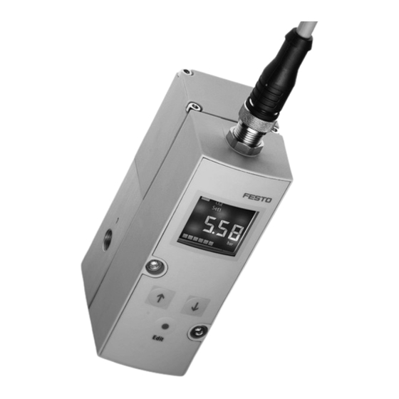
VPPM−...C1 Bedienteile, Anschlüsse und Varianten Bedienteile und Anschlüsse des VPPM−...C1 (Muffenventil) Elektrischer Anschluss M12 (8−polig) UP−Taste Typenschild Anschluss 1, Druckluft (Druckeingang) Display Anschluss 2, Arbeitsluft (Druckausgang) DOWN−Taste Anschluss 3, Entlüftung EDIT−Taste Durchgangsbohrung zur Befestigung Bild 1 Festo VPPM−...C1 0703NH Deutsch... -
Page 5: Pneumatische Anschlüsse Des Vppm
VPPM−...C1 Pneumatische Anschlüsse des VPPM−...C1 (Flanschventil) Kanal Druckluft (Druckeingang) Kanal Entlüftung Kanal Arbeitsluft (Druckausgang) Bild 2 Festo VPPM−...C1 0703NH Deutsch... -
Page 6: Varianten Des Vppm
P (PNP) / N (NPN) Gesamtgenauigkeit ... (2 %; Standard) / S1 (1 %) Bediengerät ... (LED) / C1 (LCD) 1) Bei Verwendung eines alternativen unteren und oberen Druckwertes, kann die Gesamtgenauigkeit des VPPM−...C1 nicht gewährleistet werden. Bild 3 Festo VPPM−...C1 0703NH Deutsch... -
Page 7: Funktion Und Anwendung
1. Um den EDIT−Mode zu aktivieren, EDIT−Taste drücken. [Out] blinkt. 2. 2 mal EDIT−Taste drücken. SP blinkt. 3. Angezeigten Schwellwert mit den UP− bzw. DOWN−Tasten ändern. 4. EDIT−Knopf 3 s gedrückt halten. Das VPPM−...C1 ist dann im RUN−Modus. Festo VPPM−...C1 0703NH Deutsch... -
Page 8: Voraussetzungen Für Den Produkteinsatz
Die Verpackungen sind vorgesehen für eine Verwertung auf stofflicher Basis (Ausnahme: Ölpapier = Restmüll). Verwenden Sie den Artikel im Originalzustand ohne jegliche eigenmächtige Veränderung. Berücksichtigen Sie die Warnungen und Hinweise am Produkt und in dieser Bedienungsanleitung. Festo VPPM−...C1 0703NH Deutsch... -
Page 9: Einbau
Achten Sie auf genügend Platz für den Kabelanschluss und die Schlauchan schlüsse. Dadurch wird ein Abknicken des Anschlusskabels vermieden. Platzieren Sie das VPPM−...C1 möglichst nahe am Verbraucher. Dies führt zu besse rer Regelgenauigkeit und kürzeren An sprechzeiten. Bild 7 Festo VPPM−...C1 0703NH Deutsch... - Page 10 Schrauben an das VPPM−...C1 (Anzugsdrehmoment ca. 1,0 Nm): für Á": M4 x 65 für ¼": M4 x 75 S Hängen Sie das VPPM−...C1 in die Hutschiene. S Sichern Sie das VPPM...C1 mit den Sicherungsschrauben des Hutschienenadapters (Anzugsdrehmoment 1,5 Nm). Bild 8 Festo VPPM−...C1 0703NH Deutsch...
- Page 11 VPPM−...C1 Ó Ó Ó Ó Ó Ó Ó Ó Ó Ó Ó Ó Ô Ô Ô Ô Ó Ó Ó Ó Ó Ó Ó Ó Befestigungsschrauben M4 Hutschienen−Klemmeinheit VPPM−...C1 Hutschienenadapter Typ VAME−P1−T Hutschiene Bild 9 Festo VPPM−...C1 0703NH Deutsch...
-
Page 12: Bild
Stellen Sie sicher, dass die Kabel quetsch−, knick− und dehnungsfrei verlegt sind: Verwenden Sie das vorkonfektionierte Bild 11 Steckdosenkabel von Festo (siehe Ab schnitt 10 Zubehör"). Dadurch ist ge währleistet, dass die vorgegebene Schutzart IP 65 und EMV erreicht wird. Festo VPPM−...C1 0703NH Deutsch... - Page 13 Verkabeln Sie das VPPM−...C1 gemäß des entsprechenden Anschlussbildes: Anschlussbilder VPPM−...C1 Spannungsvariante Stromvariante Typ VPPM−...−V1...C1 Typ VPPM−...−A4...C1 0...10 V 4...20 mA w− w− D1 ext in D2 ext in D1 ext in D2 ext in Bild 12 Festo VPPM−...C1 0703NH Deutsch...
- Page 14 (RD) Digitaler Ausgang D3 PE Schirmgeflecht auf Gewinde Bei Verwendung der Anschlussdose mit Kabel lt. Zubehör Das Anzugsdrehmoment beträgt max. 0,5 Nm Bild 13 Schaltbilder VPPM−...C1 Schaltausgang + 24 V + 24 V Bild 14 Festo VPPM−...C1 0703NH Deutsch...
-
Page 15: Inbetriebnahme
Sie sicher das an den digitalen Eingängen D1 und D2 ein 0−Si gnal anliegt. S Den gewünschten Werks−Parametersatz können Sie im Menü EDIT am VPPM−...C1 auswählen (siehe Bild 21). Ab Werk ist der Parametersatz Set2 (universelles Regelverhalten) vorgewählt. Festo VPPM−...C1 0703NH Deutsch... - Page 16 Auswahl des gewünschten Parame tersatzes über das Display des VPPM−...C1 1 = 24 V DC / 0 = 0 V DC Bild 15 Symbolik auf dem Display des VPPM−...C1 Menüebene Symbol Beschreibung Schaltausgang gesetzt / nicht gesetzt Festo VPPM−...C1 0703NH Deutsch...
- Page 17 [Lock] Sicherheitscode aktiv (Sperrung gegen un befugte Programmierung) [kPa], [psi], [bar] Einheiten des Drucks, umschaltbar Druckanzeige als Balkendiagramm 1) Abhängig von der Variante des VPPM−...C1 2) Abhängig von der eingestellten Einheit im Menü SPEC Bild 16 Festo VPPM−...C1 0703NH Deutsch...
- Page 18 Minimaler Druckwert [min] Maximaler Druckwert [max] Drücken Sie mehrmals hintereinander die DOWN−Taste und prüfen Sie die ak tuellen Werte von [In]. Nach Anzeige des Maximaldrucks erfolgt durch erneutes drücken der DOWN−Taste die Rückkehr in den RUN−Modus. Festo VPPM−...C1 0703NH Deutsch...
- Page 19 Wählen der Druckeinheit [kPa, psi, bar] (je nach Einstellung im Menü [SPEC] ) oder [mA/V] oder [%] Im Menü Set: Auswahl eines Werks−Parametersatzes [Set1], [Set2] oder [Set3] Im Menü SPEC: Einstellen des Sicherheitscode [Lock] und der Druckeinheit [kPa, psi, bar] Festo VPPM−...C1 0703NH Deutsch...
- Page 20 Konfigurieren des Schaltausgangs (Out) Warnung Abhängig von der Funktionalität der Maschine/Anlage kann die Manipulation von Signalzuständen schwere Personen− oder Sachschäden verursachen. S Berücksichtigen Sie, dass das Ändern des Schaltverhaltens der Schaltaus gänge im EDIT−Modus sofort wirksam wird. Festo VPPM−...C1 0703NH Deutsch...
- Page 21 Bei Einstellung NO (Schließer) Bei Einstellung NC (Öffner) Bei Einstellung Schwellwert− Komparator Bei Einstellung Fenster− Komparator SP min SP max SP min SP max Bei Einstellung Hysterese p [bar] SP.O. Istwert Sollwert U [V] SP.O.−Signal Bild 18 Festo VPPM−...C1 0703NH Deutsch...
- Page 22 ) einstellen mit UP/DOWN−Taste und mit EDIT−Taste bestätigen. [HY] blinkt. 7. Hysterese (HY) einstellen mit UP/DOWN−Taste und mit EDIT−Taste bestätigen. [NO] bzw. [NC] blinkt. 8. Schaltcharakteristik (NO/NC) einstellen mit UP/DOWN−Taste und mit EDIT−Taste bestätigen. Der VPPM−...C1 ist wieder im RUN−Modus. Bild 19 Festo VPPM−...C1 0703NH Deutsch...
- Page 23 4. Mit UP− bzw. DOWN−Tasten gewünschte Werks−Parametersatz auswählen. Set1 (Parametersatz 1): schnelles Regelverhalten Set2 (Parametersatz 2): universelles Regelverhalten Set3 (Parametersatz 3): präzises Regelverhalten Ausgewählter Parametersatz blinkt. Zur Bestätigung EDIT−Knopf drücken. Der VPPM−...C1 ist wieder im RUN−Modus. Bild 21 Festo VPPM−...C1 0703NH Deutsch...
- Page 24 24 VDC ± 10%). Belüften Sie das VPPM−...C1 mit einem mindestens um 1 bar höheren Ein gangsdruck als der maximal gewünschte Ausgangsdruck. Es stellt sich ein dazu proportionaler Ausgangsdruck p2 ein. Dem Sollwertsignal ist dann fol gender Ausgangsdruck zugeordnet: Festo VPPM−...C1 0703NH Deutsch...
-
Page 25: Bedienung Und Betrieb
> 1000 ml 1) bei Schlauchdurchmesser 6mm oder 8mm Bild 24 Bedienung und Betrieb Hinweis S Stellen Sie sicher, dass beim Abschalten des VPPM−...C1 zuerst der Versor gungsdruck, danach die Sollwertspannung und zuletzt die Versorgungsspan nung abgeschaltet wird. Festo VPPM−...C1 0703NH Deutsch... -
Page 26: Vppm
[Out] blinkt: Zürücksetzen aller Ausgangsparameter. [In] blinkt: Zürücksetzen aller Eingangsparameter. [All] blinkt: Zürücksetzen aller Aus− und Eingangsparameter sowie des Sicherheits− code 5. Drücken Sie die EDIT−Taste zum Zurücksetzen der gewählten Parameter Der VPPM−...C1 ist wieder im RUN−Modus. Bild 25 Festo VPPM−...C1 0703NH Deutsch... -
Page 27: Wartung Und Pflege
Demontieren Sie das VPPM−...C1 von der Befestigungsfläche/Hutschiene. Zubehör Bezeichnung Steckdosenkabel gerade SIM−M12−8GD−..−PU Steckdosenkabel gewinkelt NEBU−M12W8−..−N−LE8 Y−Anschlusskabel (zum Anschließen des VPPM−... an analoge Ein−/Ausgänge) NEBV−M12G8−KD−...−M12G5 Hutschienenbefestigung VAME−P1−T Winkel (nur für statische Anwendungen) VAME−P1−A P−Anschlussleiste VABM−P1−SF−G18−..−P3 Bild 26 Festo VPPM−...C1 0703NH Deutsch... -
Page 28: Sicherheitseinstellung
Fehleranzeige im Display Unterschreiten des Grenzwertes (Sollwertes) Er.09 Überschreiten des Grenzwertes (Sollwertes) Er.10 Hardwarefehler Er.15 Unterspannung der 24 V Betriebsspannung Er.05 Überspannung der 24 V Betriebsspannung Er.26 Sollwertvorgabe überschritten Er.01 Temperaturbereich im VPPM−...C1 überschritten Er.28 Bild 27 Festo VPPM−...C1 0703NH Deutsch... - Page 29 Versorgungs Versorgungsdruck erhöhen druck p1 UP/DOWN−Tasten Auf den digitalen Eingängen An digitale Eingänge D1 und am VPPM−... rea D1 und D2 liegt Spannung D2 0 V DC anlegen. gieren nicht. Bild 28 Festo VPPM−...C1 0703NH Deutsch...
-
Page 30: Technische Daten
Zul. Temperaturbereich Umgebungstemperatur [°C] 0...+60 Mediumstemperatur [°C] +10...+50 Lagertemperatur [°C] 10...+70 El. Anschluss Steckkontakt M12x1, 8−polig Zul. Betriebsspannung [V DC] 21,6 ... 26,4 (zul. Restwelligkeit max. 10 %) 1) Befestigungsschrauben des VPPM sind angezogen Bild 29 Festo VPPM−...C1 0703NH Deutsch... - Page 31 5 g Beschleunigung bei 60 ... 150 Hz geprüft nach DIN/IEC 68/EN 60068 Teil 2−27; Bei Wandmontage: +/−30 g bei 11 ms Dauer; 5 Schocks je Rich tung Werkstoffe Gehäuse AL−Knetlegierung Deckel PAXMD6−GF50/gr−P; PA6−GB20,GF10/gr−P Dichtungen Schmierung silikonfrei Gewicht 400 g Bild 30 Festo VPPM−...C1 0703NH Deutsch...
- Page 32 VPPM−...C1 Durchflusskennlinien 2 bar Ventilvariante: Typ VPPM−6L−...−OL2H−...: 6 bar Ventilvariante: Typ VPPM−6L−...−OL6H−...: 10 bar Ventilvariante: Typ VPPM−6L−...−OL10H−...: Bild 31 Festo VPPM−...C1 0703NH Deutsch...
-
Page 33: Menüstruktur
(lock Sperrung gegen unbefugte Programmierung) Sicherheitscode inaktiv (lock) Taste (hier UP−Taste) drücken UP− oder. DOWN−Taste drücken zum Einstellen von Werten oder Wählen von Funktionen) UP− oder. DOWN−Taste drücken zum Wechseln der Funktionen im Menü EDIT−Taste drücken Bild 32 Festo VPPM−...C1 0703NH Deutsch... - Page 34 VPPM−...C1 1) Abhängig von der Ausführung des VPPM−...C1 2) Abhängig von der Einstellung im Menü [SPEC] Bild 33: EDIT−Modus Festo VPPM−...C1 0703NH Deutsch...
- Page 35 VPPM−...C1 1) Abhängig von der Einstellung im Menü [Out] im EDIT−Mode Bild 34: SHOW−Modus Festo VPPM−...C1 0703NH Deutsch...
- Page 36 VPPM−...C1 Festo VPPM−...C1 0703NH Deutsch...
- Page 37 ..........Festo VPPM−...C1 0703NH English...
-
Page 38: Operating Parts, Connections And Variants
Operating parts and connections of the VPPM−...C1 (inline valve) Electrical connection M12 (8−pin) UP button Rating plate Connection 1, compressed air (pressure input) Display Connection 2, work air (pressure output) DOWN button Connection 3, exhaust EDIT button Through hole for fastening Fig. 1 Festo VPPM−...C1 0703NH English... -
Page 39: Pneumatic Connections Of The Vppm
VPPM−...C1 Pneumatic connections of the VPPM−...C1 (flange valve) Compressed air channel (pressure input) Exhaust channel Work air channel (pressure output) Fig. 2 Festo VPPM−...C1 0703NH English... -
Page 40: Variants Of The Vppm
... (2 %; standard) / S1 (1 %) Operating unit ... (LED) / C1 (LCD) 1) If an alternative lower and upper pressure value is used, the total accuracy of the VPPM−...C1 can not be guaranteed. Fig. 3 Festo VPPM−...C1 0703NH English... -
Page 41: Function And Application
2. Press the EDIT button twice. SP flashes. 3. Modify the threshold value shown with the UP or DOWN button. 4. Hold the EDIT button pressed down for 3 s. The VPPM−...C1 will then be in the RUN mode. Festo VPPM−...C1 0703NH English... -
Page 42: Conditions Of Use
(exception: oiled paper = other waste). Use the product in its original state. Unauthorized modification is not permitted. Note the warnings and instructions on the product and in the relevant operating instructions. Festo VPPM−...C1 0703NH English... -
Page 43: Fitting
In this way you will prevent the connecting cable from being bent. Place the VPPM−...C1 as near as possible to the consuming device. This will lead to better control accuracy and shorter re sponse times. Fig. 7 Festo VPPM−...C1 0703NH English... - Page 44 Á:": M4 x 65 for ¼": M4 x 75 S Hang the VPPM−...C1 onto the hat rail. S Secure the VPPM...C1 with the locking screws of the hat rail adapter (tightening torque 1.5 Nm). Fig. 8 Festo VPPM−...C1 0703NH English...
- Page 45 Ó Ó Ó Ó Ó Ó Ó Ó Ô Ô Ó Ó Ô Ô Ó Ó Ó Ó Ó Ó Ó Ó Mounting screws (M4) Hat rail clamping unit VPPM−...C1 Hat rail adapter type VAME−P1−T Hat rail Fig. 9 Festo VPPM−...C1 0703NH English...
- Page 46 Make sure that the cables are not squashed, bent or stretched. Use the ready−made cable socket from Festo (see section 10 Accessories"). Fig. 11 You can then guarantee that the specified protection clss IP 65 and EMC are ful filled.
- Page 47 Current variant Type VPPM−...−V1...C1 Type VPPM−...−A4...C1 0...10 V 4...20 mA w− w− D1 ext in D2 ext in D1 ext in D2 ext in Fig. 12 The individual pins on the electrical connection are assigned as follows: Festo VPPM−...C1 0703NH English...
- Page 48 PE braiding on thread Using the connector socket with cable as per Accessories" The tightening torque amounts to max. 0.5 Nm Fig. 13 Circuit diagrams for the VPPM−...C1 switching output + 24 V + 24 V Fig. 14 Festo VPPM−...C1 0703NH English...
-
Page 49: Commissioning
0−signal at digital inputs D1 and D2. S You can select the desired factory parameter set in the EDIT menu on the VPPM−...C1 (see fig. 21). Parameter set 2 (universal control reaction) is preselected at the factory. Festo VPPM−...C1 0703NH English... - Page 50 VPPM− C1 1 = 24 V DC / 0 = 0 V DC Fig. 15 Symbols on the display of the VPPM−...C1 Menu level Symbol Description Switching output set/not set Festo VPPM−...C1 0703NH English...
- Page 51 Security code active (locked against unauthor ized programming) [kPa], [psi], [bar] Units of pressure, can be switched Pressure display as bar chart 1) Depends on the variant of the VPPM−...C1 2) Depends on unit set Fig. 16 Festo VPPM−...C1 0703NH English...
- Page 52 [max] Press the DOWN button several times and check the current values of [In]. When the maximum pressure is displayed you can return to the RUN mode by pressing the UP button again. Festo VPPM−...C1 0703NH English...
- Page 53 3. Press the UP/DOWN button until [In] flashes in the display, then press the EDIT button. [min] flashes. Modify the pressure regulating range: 4. Set minimum pressure value with UP/DOWN buttons, then press the EDIT button. [max] flashes. 5. Set maximum pressure value with UP/DOWN buttons, then press the EDIT button. Festo VPPM−...C1 0703NH English...
- Page 54 S Note that if the switching reaction of the switching outputs is modified in the EDIT mode, the new status will be effective immediately. Define the desired switching behaviour of the switching output D3. Festo VPPM−...C1 0703NH English...
- Page 55 With setting Window comparator SP min. SP max. SP min. SP max. With setting Hysteresis p [bar] SP. O. (setpoint Actual value value reached) Setpoint value SP.O (setpoint value reached) U [V] signal Fig. 18 Festo VPPM−...C1 0703NH English...
- Page 56 7. Set the hysteresis (HY) with the UP/DOWN button and confirm with the EDIT button. [NO] or [NC] flashes. 8. Set the switching characteristic (NO/NC) with the UP/DOWN button and confirm with the EDIT button. The VPPM−...C1 is then in the RUN mode again. Fig. 19 Festo VPPM−...C1 0703NH English...
- Page 57 Set2 (parameter record 2): universal control reaction Set3 (parameter record 3): precise control reaction The selected parameter record flashes. In order to confirm, press the EDIT button. The VPPM−...C1 is then in the RUN mode again. Fig. 21 Festo VPPM−...C1 0703NH English...
- Page 58 Pressurize the VPPM−...C1 with an input pressure at least 1 bar higher than the maximum desired output pressure. An output pressure p2 proportionate thereto is then set. The following output pressure is then assigned to the setpoint value signal: Festo VPPM−...C1 0703NH English...
-
Page 59: Operation
1) with tubing diameter 6 mm or 8 mm Fig. 24 Operation Please note S When switching off the VPPM−...C1, make sure that the supply pressure is switched off first, then the setpoint value voltage and finally the supply voltage. Festo VPPM−...C1 0703NH English... -
Page 60: Resetting The Vppm
[All] flashes: All input and output parameters as well as the security code are reset. 5. Press the EDIT button in order to reset the selected parameters. The VPPM−...C1 is then in the RUN mode again. Fig. 25 Festo VPPM−...C1 0703NH English... -
Page 61: Care And Maintenance
Plug socket with cable, straight SIM−M12−8GD−..−PU Plug socket with cable, angled NEBU−M12W8−..−N−LE8 Y−connecting cable (for connecting the VPPM−... to analogue inputs/outputs) NEBV−M12G8−KD−..−M12G5 Hat rail fastening VAME−P1−T Bracket (only for static applications) VAME−P1−A Pneumatic supply manifold VABM−P1−SF−G18−..−P3 Fig. 26 Festo VPPM−...C1 0703NH English... -
Page 62: Safety Setting
Limit value exceeded (setpoint value) Er.10 Hardware fault Er.15 Undervoltage of the 24 V power supply Er.05 Overvoltage of the 24 V power supply Er.26 nominal value specification exceeded Er.01 temperature range in the VPPM−...C1 exceeded Er.28 Fig. 27 Festo VPPM−...C1 0703NH English... - Page 63 Setpoint value voltage or set Check controller and connec point value current not applied. tion. VPPM−... defective Send the device to Festo for repairs. Flow too low Restriction of the flow cross Use different type of connec section due to connection de tion.
-
Page 64: Technical Specifications
Medium temperature [°C] +10...+50 Storage temperature [°C] 10...+70 Electrical connection Plug M12x1, 8−pin Permitted operating [V DC] 21.6 ... 26.4 (permitted residual ripple max.: 10%) voltage 1) The fastening screws of the VPPM are tightened. Fig. 29 Festo VPPM−...C1 0703NH English... - Page 65 DIN/IEC 68/EN 60068 part 2−27; For wall mounting: ±30 g at 11 ms duration; 5 shocks per direction Materials Housing Al wrought alloy Cover PAXMD6−GF50/gr−P; PA6−GB20,GF10/gr−P Seals Lubrication silicone−free Weight 400 g Fig. 30 Festo VPPM−...C1 0703NH English...
- Page 66 VPPM−...C1 Characteristic curves for flow rate 2 bar valve variant: Type VPPM−6L−...−OL2H−...: 6 bar valve variant: Type VPPM−6L−...−OL6H−...: 10 bar valve variant: Type VPPM−6L−...−OL10H−...: Fig. 31 Festo VPPM−...C1 0703NH English...
-
Page 67: Menu Structure
Press the UP button or the DOWN button in order to set values or select functions) Press the UP button or the DOWN button in order to change the functions in the menu. Press the EDIT button. Fig. 32 Festo VPPM−...C1 0703NH English... - Page 68 VPPM−...C1 not in function (FORCE) 1) Depending on the design of the VPPM−...C1 2) Depending on the setting in the menu [SPEC] Fig. 33: EDIT mode Festo VPPM−...C1 0703NH English...
- Page 69 VPPM−...C1 1) Depending on the setting in the menu [Out] in the EDIT mode Fig. 34: SHOW mode Festo VPPM−...C1 0703NH English...
- Page 70 VPPM−...C1 Festo VPPM−...C1 0703NH English...
- Page 71 VPPM−...C1 Festo VPPM−...C1 0703NH...
- Page 72 Copyright: autorisation écrite expresse. Tout manquement à cette règle Festo AG & Co. KG, est illicite et expose son auteur au versement de dommages Postfach et intérêts. Tous droits réservés pour le cas de la délivrance D−73726 Esslingen...
Need help?
Do you have a question about the VPPM-**C1 Series and is the answer not in the manual?
Questions and answers