
Related Manuals for SCHUNK ROTA THW plus Series


Summary of Contents for SCHUNK ROTA THW plus Series
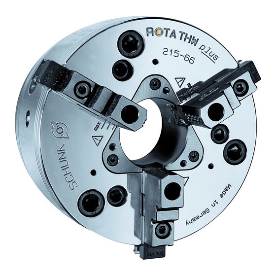
- Page 1 Translation of original operating manual Power chuck ROTA THWplus Assembly and operating manual Superior Clamping and Gripping...
- Page 2 Imprint Copyright: This manual remains the copyrighted property of SCHUNK GmbH & Co. KG. It is solely supplied to our customers and operators of our products and forms part of the product. This documentation may not be duplicated or made accessible to third parties, in particu- lar competitive companies, without our prior permission.
-
Page 3: Table Of Contents
Table of contents Table of contents 1 General ........................5 1.1 Warnings ........................5 1.2 Applicable documents ....................6 2 Basic safety instructions ................... 7 2.1 Intended use ......................7 2.2 Not intended use ...................... 7 2.3 Notes on particular risks ................... 8 2.4 Notes on safe operation .................. - Page 4 Table of contents 9 Maintenance ......................36 9.1 Lubrication ......................36 9.2 Maintenance intervals .................... 37 9.3 Technical condition ....................37 10 Disposal ........................38 11 Chuck mounts and Spare parts ................39 11.1 Chuck mounts ......................39 11.2 Spare parts ......................39 12 Drawings .........................
-
Page 5: General
General General This operating manual is an integral component of the product and contains important information on safe and proper assembly, commissioning, operation, care, maintenance and disposal. This manual must be stored in the immediate vicinity of the product where it is accessible to all users at all times. Before using the product, read and comply with this manual, espe- cially the chapter “Basic safety notes”.(... -
Page 6: Applicable Documents
• Catalog data sheet of the purchased product * • Calculation of the jaw centrifugal forces, "Technology" chapter in the lathe chuck catalog * The documents marked with an asterisk (*) can be downloaded on our homepage www.schunk.com. 01.00|ROTA THWplus |en... -
Page 7: Basic Safety Instructions
Only original SCHUNK spare parts may be used. Intended use The chuck is used to clamp workpieces on machine tools and other suitable technical facilities, paying particular attention to the tech- nical data specified by the manufacturer. -
Page 8: Notes On Particular Risks
Basic safety instructions Notes on particular risks This product may pose a danger to persons and property if, for ex- ample: • It is not used as intended; • It is not installed or maintained properly; • The safety and installation instructions, local applicable safety and accident prevention regulations or the EC Machinery Di- rective are not observed. - Page 9 Basic safety instructions DANGER Possible risk of fatal injury to operating personnel from clothing or hair being caught on the lathe chuck and being dragged into the machine Loose clothing or long hair may become caught on projecting parts of the lathe chuck and be drawn into the machine. •...
- Page 10 Basic safety instructions CAUTION Danger of limbs being crushed by opening and closing of the chuck jaws during manual loading and unloading or when re- placing moving parts. • Do not reach between the jaws. • Wear safety gloves. • Observe the safety and accident prevention regulations during operation of the chuck, especially in connection with machin- ing centers and other technical equipment.
-
Page 11: Notes On Safe Operation
Basic safety instructions CAUTION Hazard from vibration due to imbalanced rotating parts and noise generation. Physical and mental strains due to imbalanced workpieces and noise during the machining process on the clamped and rotating workpiece. • Ensure the chuck's axial and concentric runout. •... - Page 12 (clamping force, coeffi- cient of friction, wear characteristics). (For product information about LINOMAX, see the "Accesso- ries" chapter of the SCHUNK lathe chuck catalog or contact SCHUNK). • Use a suitable high-pressure grease gun to ensure that you reach all the greasing areas.
- Page 13 • If the chuck is involved in a collision, it must be subjected to a crack test before using it again. Replace damaged parts with original SCHUNK spare parts. • Replace the chuck jaw mounting screws if there are signs of wear or damage.
-
Page 14: Substantial Modifications
Basic safety instructions 2.4.1 Substantial modifications No substantial modifications may be made to the chuck. If the operator carries out a substantial modification to the chuck, the product shall no longer conform to the EC Machinery Directive 2006/42/EC. Personnel qualification Assembly and disassembly, commissioning, operation and repair of the chuck may be performed only by qualified specialists who have been instructed with respect to safety. -
Page 15: Using Personal Protective Equipment
Basic safety instructions Spare parts Only ever use original SCHUNK spare parts. Environmental regulations Comply with the applicable legal norms when disposing of waste. Using personal protective equipment When using this product, you must comply with the relevant health and safety at work rules and you must use the required personal safety equipment (minimum: category 2). -
Page 16: Warranty
Warranty Warranty If the product is used as intended, the warranty is valid for 24 months from the ex-works delivery date under the following con- ditions: ( 1.2, Page 6) • Observe the applicable documents • Observe the ambient conditions and operating conditions (... -
Page 17: Torques Per Screw
Torques per screw Torques per screw Tightening torques for mounting screws used to clamp the chuck on lathes or other suitable technical equipment (screw quality 10.9) Screw size M6 M8 M10 M12 M14 M16 M18 M20 M22 M24 M27 M30 Admissible torque 120 160 200 290 400 500 1050 1500 (Nm) -
Page 18: Scope Of Delivery
Scope of delivery Scope of delivery ROTA THW plus 165, 185, 215: Power chuck Set of base jaws Mounting screws Jaw change key Operating manual Short operating manual ROTA THW plus 260, 315: Power chuck Set of base jaws Mounting screws Jaw change key Operating manual Short operating manual... -
Page 19: Technical Data
For the chuck THW plus it's necessary to determine those jaw with data specific. Calculation examples are in the chapter fine serration "Technology" in the SCHUNK-lathe-chuck-catalog or in the [kgm] chapter "Special jaws/Technology" in the SCHUNK-power- chuck-catalog. Those catalogs are also available as down- load at www.de.schunk.com. - Page 20 The chuck is in perfect condition and lubricated with SCHUNK LINOMAX special grease. If one or more of these prerequisites is modified, the graphs will no longer be valid.
- Page 21 Technical data Clamping force / speed diagrams ROTA THW plus 215-66 Clamping force / speed diagrams ROTA THW plus 260-81 Clamping force / speed diagrams ROTA THW plus 315-104 01.00|ROTA THWplus |en...
-
Page 22: Calculations For Clamping Force And Speed
Technical data Calculations for clamping force and speed Missing information or specifications can be requested from the manufacturer! Legend Total centrifugal force [N] Centrifugal torque of top jaws [kgm] Effective clamping force [N] Centrifugal torque of base jaws [kgm] Required minimum clamping force RPM [min spmin Initial clamping force [N]... - Page 23 Technical data (–) for gripping from the outside inwards (+) for gripping from the inside outwards DANGER Risk to life and limb of the operating personnel and significant property damage when the RPM limit is exceeded! With grip- ping from the outside inwards, and with increasing RPM, the effective clamping force is reduced by the magnitude of the in- creasing centrifugal force (the forces are opposed).
-
Page 24: Calculation Example: Required Initial Clamping Force Fsp0 For A Given Rpm N
Technical data NOTICE This calculated force must not be larger than the maximum clamping force ΣS engraved on the chuck. See also "Chuck data" table ( 6.1, Page 19) From the above formula it is evident that the sum of the effective clamping force F and the total centrifugal force F is multiplied by... - Page 25 Technical data • max. speed of rotation n = 3200 ("Chuck data" table) • RPM n = 1200 (application-specific) • Mass of one (!) top jaw m = 5.33 kg (application- specific) • Center of gravity radius of top jaw r = 0.107 m (application- specific) •...
-
Page 26: Calculation Of The Permissible Rpm Nzul In Case Of A Given Initial Clamping Force Fsp0
Technical data 6.3.3 Calculation of the permissible rpm nzul in case of a given initial clamping force Fsp0 The following formula can be used to calculate the permissible RPM for a given initial clamping force during shutdown: NOTICE The calculated permissible RPM may not exceed the maximum RPM inscribed on the chuck for safety reasons! Example of calculation: Permissible RPM for a given effective clamping force... -
Page 27: Permissible Imbalance
Technical data Permissible imbalance The permissible imbalance for lathe chucks is quality class G 6.3 as per DIN ISO 1940-1. 01.00|ROTA THWplus |en... -
Page 28: Attachment And Disassembly Of The Chuck
Attachment and disassembly of the chuck Attachment and disassembly of the chuck The item numbers specified for the corresponding individual com- ponents relate to chapter drawings.( 12, Page 41) Pre-assembly measures Carefully lift the product (e.g. using suitable lifting gear) from the packaging. - Page 29 Attachment and disassembly of the chuck with a depth gauge R2 = R1 + 0.3 mm (max. + 0.5 mm) You have to ensure that the piston can be moved to the foremost (jaw change) position. To do this, ensure that the dimensions for the attachment (see Fig.
- Page 30 Lubricate before commissioning the chuck Before commissioning, move the chuck in the open position. Press three strokes SCHUNK special grease LINOMAX into each of the grease nipples using a high-pressure grease gun. To achieve the optimal grease distribution and the maximum clamping force, close and open the chuck several times over the entire clamping stroke.
-
Page 31: Disassembling And Assembling The Chuck
Attachment and disassembly of the chuck Disassembling and assembling the chuck The chuck may only be disassembled once it has been uninstalled (see Mounting the chuck, chapter 7.2). • You can leave the base jaws (item 2) in the chuck. Move them to the outermost permissible position. - Page 32 Clean all individual components and check them for damage and wear. Only original SCHUNK spare parts may be used. The chuck is assembled in the same way but in the reverse order. Before installation, lubricate parts well with LINO MAX special grease.
-
Page 33: Function And Handling
Function and handling Function and handling The item numbers specified for the corresponding individual com- ponents relate to chapter drawings.( 12, Page 41) Function of the chuck The type THW plus quick-change power chucks are actuated using a rotating solid or through-hole cylinder. The axial tensile or com- pressive forces are converted to the radial jaw clamping force via wedge bars positioned tangentially to the chuck body. -
Page 34: Base Jaw Position
Function and handling NOTICE The chuck piston (item 3) must not be moved so long as the jaw change key (item 90) is located in one of the jaw-change bolts (item 8) for the chuck. Risk of damage to the chuck. NOTICE The mechanical system of the chuck is opened when the protec- tion sleeve (item 4) is changed. - Page 35 Function and handling • Keep the base jaws and top jaws screwed in place for recurring work. Tighten the jaw mounting screws to the specified torque ( 4, Page 17). Tighten the jaw mounting screws with a torque wrench. On no account tighten the screws with an extension pipe or with ham- mer blows.
-
Page 36: Maintenance
Number of strokes Lubricate all three segments evenly in order to avoid imbalances. (For product information about LINO MAX, see the "Accessories" chapter of the SCHUNK lathe chuck catalog or contact SCHUNK). CAUTION Allergic reactions due to grease in contact with skin! Wear gloves. -
Page 37: Maintenance Intervals
If the clamping force has dropped too far or if the base jaws and clamping piston no longer move properly, the chuck has to be dis- assembled, cleaned, and relubricated. Only original SCHUNK spare parts may be used. 01.00|ROTA THWplus |en... -
Page 38: Disposal
• Dispose of the chuck's metal parts as scrap metal. Alternatively, you can return the chuck to SCHUNK for proper dis- posal. 01.00|ROTA THWplus |en... -
Page 39: Chuck Mounts And Spare Parts
Chuck mounts and Spare parts Chuck mounts and Spare parts 11.1 Chuck mounts SCHUNK type Chuck mount Id-No. ROTA THW plus 165-43 Z 140 0800600 0800601 0800602 ROTA THW plus 185-52 Z 140 0800610 Z 170 0800611 0800612 0800613 ROTA THW plus 215-66... - Page 40 Chuck mounts and Spare parts Item Designation Quantity Thrust bolt Spring bolt Safety bolt Plunger pin Pressure piece Retainer ring (size 260/315 only) Center sleeve (size 260/315 only) Assembly tool Lever for assembly tool Center sleeve seal (from size 250) Piston seal Adapter seal Jaw-change bolt seal...
-
Page 41: Drawings
Drawings Drawings 01.00|ROTA THWplus |en... - Page 42 Drawings 01.00|ROTA THWplus |en...
-
Page 43: Translation Of The Original Declaration Of Incorporation
Translation of the original declaration of incorporation in terms of the Directive 2006/42/EG, Annex II, Part 1.B of the European Parliament and of the Council on machinery. Manufacturer/ H.-D. SCHUNK GmbH & Co. Spanntechnik KG Distributor Lothringer Str. 23 D-88512 Mengen... -
Page 44: Appendix On Declaration Of Incorporation, As Per 2006/42/Ec, Annex Ii, No. 1 B
Appendix on Declaration of Incorporation, as per 2006/42/EC, annex II, No. 1 B Appendix on Declaration of Incorporation, as per 2006/42/EC, annex II, No. 1 B Product designation Power-actuated chuck with quick jaw change Type designation THW plus in sizes 165-43, 185-52, 215-66, 260-81, 315-104 ID number 0800600, 0800601, 0800602, 0800610, 0800611, 0800612, 0800613, 0800620, 0800621, To be provided by the System Integrator for the overall machine ⇓... - Page 45 Appendix on Declaration of Incorporation, as per 2006/42/EC, annex II, No. 1 B Risks due to other hazards 1.5.1 Electricity supply 1.5.2 Static electricity 1.5.3 Energy supply other than electricity 1.5.4 Errors of fitting 1.5.5 Extreme temperatures 1.45.6 Fire 1.5.7 Explosion 1.5.8 Noise...
Need help?
Do you have a question about the ROTA THW plus Series and is the answer not in the manual?
Questions and answers