
Related Manuals for Allen-Bradley RightSight 42EF Series


Summary of Contents for Allen-Bradley RightSight 42EF Series
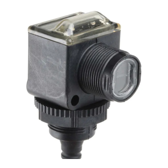
- Page 1 User Manual 42EF RightSight™ Photoelectric Sensors with IO-Link Interface 42EF-D2*, 42EF-P2-*...
- Page 2 Important User Information Read this document and the documents listed in the additional resources section about installation, configuration, and operation of this equipment before you install, configure, operate, or maintain this product. Users are required to familiarize themselves with installation and wiring instructions in addition to requirements of all applicable codes, laws, and standards.
-
Page 3: Table Of Contents
Table of Contents 1. Product Overview..........1 Product Description . - Page 4 Table of Contents Appendix E — Abbreviations........71 Rockwell Automation Publication 42EF-UM001A-EN-P - September 2015—Draft: 10/29/15...
-
Page 5: Product Overview
Product Overview Product Description The Allen-Bradley® 42EF RightSight™ with IO-Link features a new user interface boosting ultra-bright LEDs, in an 18 mm base and nose mount. Connecting the 42EF RightSight to IO-Link allows you to take advantage of advanced sensing functionality including real-time diagnostics, automatic device configuration (ADC) and access to multiple parameters. - Page 6 Product Overview – Sensor Heartbeat™ feature helps ensure excellent reliability operation by indicating to the PLC if a sensor has lost connectivity due to sensor failure or faulty wiring. – Margin Low Alarm minimizes downtime by indicating when the sensor is about to fail due to insufficient light being reflected. –...
-
Page 7: Installation
Installation Chapter Installation User Interface LED Status Green LED Orange LED The Standard IO operation table provides LED status in the RUN mode during operation. The sensor is always in RUN mode, except when being taught. Standard IO Operation (Auto PNP/NPN) Operating Mode Indication Power is OFF Power is ON... -
Page 8: Specifications
Installation aligning diffuse mode sensors, be sure that the sensitivity is set at its maximum setting (use the single-turn adjustment knob on the front panel). Pan the sensor left, right, up, and down to center the beam on the target. It might then be necessary to decrease this setting to prevent the sensor from detecting a background object. -
Page 9: Mounting
Installation Mounting Securely mount the sensor on a firm, stable surface, or support. An application, which is subject to excessive vibration or shifting, can cause intermittent operation. For installation convenience, Rockwell Automation® offers a wide range of brackets for mounting (see the Accessories section for more details). Dimensions The following illustration shows the relevant device dimensions [mm (in.)]: 34.5... -
Page 10: Typical Response Curves
Installation Typical Response Curves Visible Red Polarized Retrorefle tive— Visible Red Diffus — 3.0 m Margin Curve 500 mm Margin Curve 92-47 92-124 92-39 0 0 1 1000 0 0 0 0 0 0 Distance to Target (mm) Visible Red Diffus — Visible Red Polarized Retrorefle tive—... - Page 11 Installation Output Wiring Light Operate PNP and NPN Models (42EF-D2JBAK-1, 42EF-P2JBB-1) Brown (1) White (2) NPN light operate or disabled for IO-Link (default) Black (4) PNP light operate or IO-Link Blue (3) Dark Operate PNP and NPN Models (42EF-D2KBAK- , 42EF-P2KBB- Brown (1) White (2) NPN dark operate or disabled for IO-Link (default)
-
Page 12: Ef Rightsight Sensor With Io-Link Overview
42EF RightSight Sensor with IO-Link Overview Chapter 42EF RightSight Sensor with IO-Link Overview What Is IO-Link? The IO-Link technology is an open point-to-point communication standard and was launched as (IS) IEC 61131-9. IO-Link is now the first globally standardized technology for sensor and actuator communication with a field bus system. -
Page 13: How Does Io-Link Work
42EF RightSight Sensor with IO-Link Overview Real-time Diagnostics and Trending • Real-time monitoring of the entire machine down to the sensor level • Optimized preventative maintenance—identify and correct issues before failures can occur • Detect sensor malfunctions/failure Sensor Health Status •... - Page 14 42EF RightSight Sensor with IO-Link Overview The response time of an IO-Link system might not be fast IMPORTANT enough for high-speed applications. In this case, it is possible to monitor/configure the sensor through IO-Link on pin four of the sensors while connecting pin two (if the sensor offers a second output) of the sensor to a standard input card.
-
Page 15: Io-Link Data Types
42EF RightSight Sensor with IO-Link Overview IO-Link Data Types There are four data types available through IO-Link: Process data Cyclic data Value status Cyclic data Device data Acyclic data Events Acyclic data Process Data The process data of the devices are transmitted cyclically in a data frame in which the size of the process data is specified by the device. -
Page 16: Start-Up Of The I/O System
Rockwell Automation is the only supplier who provides every piece of the Connected Enterprise solution from top to bottom. Plus, exclusive features, and Premier Integration between Allen-Bradley® components and an Integrated Architecture® system allow for a seamless connection and commission of control components. -
Page 17: Premier Integration
IO and configuration data across the Integrated Architecture system. Using a Rockwell Automation solution, provides a smooth, consistent integration of Allen-Bradley IO-Link enabled devices into the system. To simplify the integration of the Rockwell Automation IO-Link devices to the Rockwell Automation architecture, there is an IO-Link Add-on Profile (AOP) available for the 1734-4IOL master module. -
Page 18: 42Ef Io-Link Features
42EF RightSight Sensor with IO-Link Overview 42EF IO-Link Features The 42EF VisiSight™ communicates the following parameters via IO-Link: Sensor Heartbeat feature helps ensure excellent reliability operation by indicating to the PLC if a sensor has lost connectivity due to sensor failure or faulty wiring. - Page 19 Name resides in the project and the sensor itself. Tag Naming for I/O Data: Rockwell Automation system solutions provide tag names that are based on the Allen-Bradley sensor connected. I/O data is converted, formatted, and named based on the Allen-Bradley sensor applied.
- Page 20 42EF RightSight Sensor with IO-Link Overview Reduces commissioning time by the OEM and reduces troubleshooting time by the end user when searching for sensor data. Consistent naming techniques used. Rockwell Automation Publication 42EF-UM001A-EN-P - September 2015...
-
Page 21: Setting Up The 42Ef For Io-Link Mode
Setting up the 42EF for IO-Link Mode Chapter Setting up the 42EF for IO-Link Mode This chapter shows the physical hardware and software required to configure the 42EF through IO-Link and provides a simple guide to setting up the hardware. Products required: Hardware •... -
Page 22: Example: Setting Up The Hardware
Setting up the 42EF for IO-Link Mode Example: Setting Up In this example, we are showing an Allen-Bradley POINT I/O chassis with a 1734-AENTR adapter and a 1734-4IOL IO-Link master module in the first the Hardware slot. The 1734-AENTR is communicating with a CompactLogix™ controller via EtherNet/IP. - Page 23 Setting up the 42EF for IO-Link Mode 6. After connecting the sensor, you will need to create/open a project in Studio 5000 to establish communication with the Allen-Bradley controller that is being used and to add the 1734-AENTR adapter and 1734-4IOL IO-Link master module to Controller Organizer Tree (see Chapters 6 and 7 for detailed instructions).
-
Page 24: Creating A Project
Creating a Project Chapter Creating a Project To begin a new project in Studio 5000, follow these steps. If there’s an existing project within Studio 5000 with CompactLogix or ControlLogix hardware that is installed and communicating online, go directly to Chapter 7 “Configuring the IO-Link Master.” 1. - Page 25 Creating a Project 4. After selecting the controller, name the project and click “Next.” In this example, the project name is “Project42EF.” 5. Once the project opens up, setup the IP address of the controller to help ensure communication. To set the IP address, click the browsing icon. Rockwell Automation Publication 42EF-UM001A-EN-P - September 2015...
-
Page 26: Aop Installation
Creating a Project 6. Select the controller that is being used for the project. In this example, we are using a 1769-L24ER-QB1B CompactLogix. 7. Click “Go Online” to start communicating. The next step is to configure the IO-Link Master. AOP Installation Next, verify that Studio 5000 contains the 1734-4IOL IO-Link AOP. -
Page 27: Configuring Io-Link Master
Configuring the IO-Link Master Chapter Configuring the IO-Link Master 1. Make sure that the controller is offline to configure the IO-Link Master. 2. In the controller organizer tree, find Ethernet under I/O Configuration and right-click to “add new module.” Rockwell Automation Publication 42EF-UM001A-EN-P - September 2015... - Page 28 Configuring the IO-Link Master 3. The module window pops up and show the available modules. Select the “1734-AENTR, 1734 Ethernet adapter, two-port, twisted-pair media” and click Create. 4. Name the Ethernet adapter (in this example our adapter name is “adapter”), set the chassis size, check the module revision and set-up the adapter IP address.
- Page 29 Configuring the IO-Link Master 5. The 1734 AENTR now appears in the Controller Organizer tree. 6. Right-click on 1734-AENTR adapter, and then select “New Module.” Rockwell Automation Publication 42EF-UM001A-EN-P - September 2015...
- Page 30 Configuring the IO-Link Master 7. Select “1734-4IOL” and click Create. 8. Another screen appears showing the IO-Link Configuration screen. 9. Name the IO-Link Master and click OK. Rockwell Automation Publication 42EF-UM001A-EN-P - September 2015...
- Page 31 Configuring the IO-Link Master The 42EF can now be configured. To configure the sensor, a sensor specific IODD (IO Device Description) file is required. The next steps will show how to register the IODD file. Rockwell Automation Publication 42EF-UM001A-EN-P - September 2015...
-
Page 32: Registering The 42Ef Iodd
Registering the 42EF IODD Chapter Registering the 42EF IODD To initialize a sensor on an IO-Link Master, register the IODD of the sensor. The IO Device Description (IODD) files contain the information that is related to the sensor, integrated into the system environment. By default, the IODDs are already located in the AOP Library. - Page 33 Registering the 42EF IODD 2. Select the IO-Link configuration tab. The IO-Link configuration screen appears. Rockwell Automation Publication 42EF-UM001A-EN-P - September 2015...
- Page 34 Registering the 42EF IODD 3. Right-click the left section of the screen where the channel information is located and click “Register IODD.” Rockwell Automation Publication 42EF-UM001A-EN-P - September 2015...
- Page 35 Registering the 42EF IODD 4. Select the IODD file that is needed for the sensor being configured and double-click. 5. Then click “Exit.” The IODD registration is complete. Rockwell Automation Publication 42EF-UM001A-EN-P - September 2015...
-
Page 36: Connecting The 42Ef To The Io-Link Master
Connecting the 42EF to the IO-Link Master Chapter Connecting the 42EF to the IO-Link Master Once the IODD file is registered, the sensor must be connected to the IO-Link master. The controller must always be off line to add a device to the IO- Link Master. - Page 37 Connecting the 42EF to the IO-Link Master 3. Select the appropriate sensor and double-click or click “Create.” 4. Go “OK” to accept configuration. 5. Go online to communicate The following pages describe each tab of the 1734-4IOL AOP in detail and how to teach the sensor. The following pages describe each tab of the 1734-4IOL AOP in detail and how to teach the sensor.
-
Page 38: Exploring The 42Ef Io-Link Parameters
Exploring the 42EF IO-Link Parameters Chapter Exploring the 42EF IO-Link Parameters Overview The 42EF offers four different tabs to describe the sensor functionality and operation. These tabs are: Common Tab: Provides general product information about the sensor specifications and IO-link IODD information. Observation Tab: Provides device monitoring parameters with signal strength ON, signal strength OFF, contrast, and gain. -
Page 39: Io-Link Configuration
Exploring the 42EF IO-Link Parameters IO-Link Configuration Common Tab This tab contains the following sensor information: Vendor: Provides the vendor name of the product. Vendor Text: Field used to describe additional product information. Vendor ID: Describes the vendor ID of the manufacturer of the product as designated in the IO-Link consortium. - Page 40 Exploring the 42EF IO-Link Parameters Bitrate: Displays the supported bitrate for communications as defined in the IO-link 1.1 standard. Minimum Cycle Time: SIO Mode: Describes if the sensor is also designed to operate without an IO-Link connection. IODD: Displays the complete file name of the IODD that is assigned to the product.
- Page 41 Exploring the 42EF IO-Link Parameters Observation Tab Parameter Tab Rockwell Automation Publication 42EF-UM001A-EN-P - September 2015...
- Page 42 Exploring the 42EF IO-Link Parameters The parameter tab displays the sensor parameter settings, as well as enabling the user to read data from the sensor or teach the sensor by writing new values. The parameter section is divided into three sections: •...
- Page 43 Exploring the 42EF IO-Link Parameters default value for this parameter is 1.5 with multiple selections that could reach a maximum of 20X. This means that the sensor will need to have at least 20 times the amount of light for the Green LED to stop flashing. Counter/Timer Configuration: In this section, the operator is able to configure the sensor counter and timer functions.
- Page 44 Exploring the 42EF IO-Link Parameters Margin: Displays the status of the sensor margin low alarm. This process data element is a bit that indicates to the operator if the sensor signal is marginal or unstable. Proximity: Displays the status of the proximity alarm. This process data element is a bit that indicates if there is an object in close proximity to the threshold (below 1.0X) when the output is OFF.
- Page 45 Exploring the 42EF IO-Link Parameters Diagnosis Tab The Diagnosis Tab is divided into five sections: • Device Access Locks, • Service Function, • Operating Information, • Temperature, and • Communications Characteristics Device Access Locks: This section displays the Device Storage Lock and the user Interface Lock parameters.
- Page 46 Exploring the 42EF IO-Link Parameters Location Indicator: This parameter activates the location indication sensor functionality. When enabled, the sensor user interface (green and orange LEDs) start flashing synchronously until the operator disables this function. This parameter is ideal for applications where the operator needs to locate a sensor in the application where there may be multiple sensors in close proximity.
-
Page 47: Manage Parameter Differences Between Io-Link Devices And Controllers
Exploring the 42EF IO-Link Parameters Actual – Since Power Up: Displays the current internal temperature of the sensor. Maximum – Since Power Up: Displays the maximum sensor internal temperature since the last time the sensor was power cycled. Maximum: Since Inception: Displays the maximum internal temperature of the sensor since the first time the sensor was ever powered ON. - Page 48 Exploring the 42EF IO-Link Parameters 1. From the IO-Link tab on the working pane, click the Refresh button. If differences are detected in the RW values, a dialog box appears. The dialog box displays mismatched information per channel, including the parameters and the values present in the device and in the controller.
- Page 49 Exploring the 42EF IO-Link Parameters 2. For each channel, select the check-box for the corrective action: • Use Device Values: Uploads the parameter values that are read from the connected IO-Link device to the project. • Use Project Values: Downloads the parameter values from the project to the connected IO-Link device.
- Page 50 Exploring the 42EF IO-Link Parameters Controller Tags In the Controller Tag view, it is possible to view the status of the sensor process data (The process data values are not viewable in the Add-on Profile.). Triggered: This process bit toggles between one or zero depending on the polarity configuration when the sensor detects the target or not.
- Page 51 Exploring the 42EF IO-Link Parameters Triggered MarginLowAlarm Description No target is present No target present, item in background is very close to the sensor threshold Target is present and sensor signal is not marginal Target is present and signal strength is marginal (0.5x < signal < 2X) Proximity: Displays the status of the proximity alarm.
-
Page 52: Troubleshooting
Troubleshooting Chapter Troubleshooting This guide is meant to help resolve common issues that occur when setting up the 42EF. Checklist Error Cause Remedy Check to see if there’s a reason for it to be switched off Power indicator The power supply is (installation or maintenance LED does not switched off. -
Page 53: Appendix A - Installing The Add-On Profile
Appendix Installing the Add-on Profile Introduction This appendix shows how to install the IO-Link Add-on Profile (AOP) with the RSLogix™ 5000 program. Add-on Profiles are files that users add to their Rockwell Automation® library. These files contain the pertinent information for configuring a device that is added to the Rockwell Automation network. - Page 54 Installing the Add-on Profile 3. Select “Next” in order to install the IO-Link module profiles, accept the license agreements, select “Next” and follow the module-profiles installation wizard. Rockwell Automation Publication 42EF-UM001A-EN-P - September 2015...
- Page 55 Installing the Add-on Profile 4. Be sure the “Install” option is selected, select “Next, ” review the install details and select “Install.” Rockwell Automation Publication 42EF-UM001A-EN-P - September 2015...
- Page 56 Installing the Add-on Profile 5. The installation process begins. The process may take several minutes. Once completed the “Next” button is available, select “Next.” Rockwell Automation Publication 42EF-UM001A-EN-P - September 2015...
- Page 57 Installing the Add-on Profile 6. Select “Finish” and review the release notes for any additional information. The IO-Link AOP installation is completed. Rockwell Automation Publication 42EF-UM001A-EN-P - September 2015...
-
Page 58: Appendix B - Device Parameters
Sub-Index Parameter Name Hex(Dec) Hex (Dec) Access Default Allowed Value Data Type (Length ) Device Information Vendor Name 0x10(16) 0x00(0) Allen-Bradley Allen-Bradley StringT Prduct Catalog Number Product Name 0x12(18) 0x00(0) 42EF-D2xxxx-x4 or 42EF-x2xxx-xx StringT 42EF-P2xxxx-x4 42EF-D2xxxx-x4 Series D Product ID... -
Page 59: Observation Tab
Device Parameters Observation Tab Index Sub-Index Parameter Name Hex(Dec) Hex (Dec) Access Default Allowed Value Data Type (Length ) Device Monitoring UIntegerT(RecordT) .SignalStrength On 0x56(86) 0x01(1) 0-65,535 bitLength=16 bitOffset=16 UIntegerT(RecordT) .SignalStrength Off 0x56(86) 0x02(2) 0-65,536 bitLength=16 bitOffset=0 UIntegerT Contrast 0x57(87) 0x00(0) 0-255 bitLength=8... -
Page 60: Parameter Tab
Device Parameters Parameter Tab Index Sub-Index Parameter Name Hex(Dec) Hex (Dec) Access Default Allowed Value Data Type (Length ) User Interface Configuration Operation Configuration Triggered1(or Triggered) Uinteger(RecordT) .Set Point - Threshold 0x3C(60) 0x01(1) 505-12923 bitLength=16 1000 bitOffset=16 Boolean (RecordT) 0 = Not Inverted, .Polarity 0x01(1) 1= Inverted... - Page 61 Device Parameters Parameter Tab (continued) Sub- Index Index Parameter Name Hex(Dec) Hex (Dec) Access Default Allowed Value Data Type (Length ) Timer Uinteger(RecordT) 0 = Disabled .Mode 0x5C(92) 0x01(1) 0 = Disabled bitLength=8 1 = Enabled bitOffset=40 Uinteger(RecordT) .Reset 0x5C(92) 0x02(2) 1 = Reset bitLength=8...
-
Page 62: Diagnosis Tab
Device Parameters Diagnostic Tab Index Sub-Index Parameter Name Hex(Dec) Hex (Dec) Access Default Allowed Value Data Type (Length ) Device Access Locks Boolean(RecordT) Device Access Locks.Parameter (Write) Access 0x0C(12) 0x00(0) 0=False 0=False Locks bitOffset=0 Boolean(RecordT) Device Access Locks.Data Storage Lock 0x0C(12) 0x01(1) 0=False... - Page 63 Device Parameters Diagnostic Tab (continued) Index Sub-Index Parameter Name Hex(Dec) Hex (Dec) Access Default Allowed Value Data Type (Length ) Temperature IntegerT(RecordT) .Actual - Since Power Up 0x5A(90) 0x01(1) -40 - 125 bitLength=8 bitOffset=32 IntegerT(RecordT) .Maximum - Since Power Up 0x5A(90) 0x02(2) -40 - 125...
-
Page 64: Process Data
Device Parameters Process Data Parameter Name Sub-Index Access Default Allowable Values Data Type (Length) BooleanT 0 = Not Triggered Triggered Depends on mode 0 = Not Triggered bitLength=32 1 = Triggered bitOffset=0 BooleanT 0 = Off MarginLowAlarm Depends on mode 0 = Off bitLength=32 1 = On... -
Page 65: Appendix C - Message Structure And Configuration Examples
Message Structure and Configuration Example Configuration Examples Appendix Message Structure and Configuration Example Configuration Examples Configuring a Message This appendix provides additional information and examples that explain how to configure a Message Instruction. Instruction In the examples that we show, we are assuming the use of the ControlLogix® controller. - Page 66 Message Structure and Configuration Example Configuration Examples Rockwell Automation Publication 42EF-UM001A-EN-P - September 2015...
- Page 67 Message Structure and Configuration Example Configuration Examples The following table identifies the data that are required to complete the Message Configuration dialog box to Read the “Vendor Name” from the 42EF: Description Value Message Type The message type is CIP Generic. CIP Generic Service Type The service type is Custom.
- Page 68 “Vendor Name” is read from the 42EF and copied into the “Read_Assembly” Array. When viewed as ASCII the name Allen-Bradley is displayed. Example Format of a Write Message It is possible to Write a unique name to the 42EF sensor. This Parameter is called “Application Specific Name.”...
- Page 69 Message Structure and Configuration Example Configuration Examples Name Parameter in the 42EF. To open the Message Instruction dialog box, click the blue square box in the Message Instruction. Rockwell Automation Publication 42EF-UM001A-EN-P - September 2015...
- Page 70 Message Structure and Configuration Example Configuration Examples The following table identifies the data that are required to complete the Message Configuration dialog box to Write “Test” to the Application Specific Name in the 42EF: Description Value Message Type The message type is CIP Generic. CIP Generic Service Type The service type is Custom.
- Page 71 Message Structure and Configuration Example Configuration Examples 3. Click “Upload” then “OK” and the new parameter values are uploaded into the controller. The new Application Specific Name can be seen when viewing the Identification Tab of the AOP for the 42EF sensor. Rockwell Automation Publication 42EF-UM001A-EN-P - September 2015...
- Page 72 Message Structure and Configuration Example Configuration Examples Service Code The table that is shown is used to determine the service code that is needed for a specific Message Instruction. Need in Implementation Service Code (Hex Class Instance Service Name Description of Service Required Required Read Subindex...
-
Page 73: Appendix D - Error Codes And Events
Error Codes and Events Appendix Error Codes and Events When an event occurs, the device signals the presence of the event to the master. The master then reads out the event. Events can be error messages and warnings/ maintenance data. Error messages are transmitted from the device to the controller via the IO-Link master. -
Page 74: Events
Error Codes and Events Events 42EF Name >>> Temperature Fault Hardware Voltage Short Name Description >>> No Malfunction Overload Overrun Underrun Fault Overrun Circuit Event Code See “1734-4IOL Events” tab 0x0000 0x4000 0x4210 0x4220 0x5000 0x5111 0x7710 0 - Device application (Remote) Event Location 1 - Master application (Local) 0 - Reserved... - Page 75 Abbreviations Appendix Abbreviations Automatic Device Configuration Add-on Instruction Add-on Profile Application Specific Name International Electrotechnical Commission IODD I/O Device Description National Electric Code Quick Disconnect Red, Green, Blue Standard I/O Teach Background Teach Dynamic Teach Mark Rockwell Automation Publication 42EF-UM001A-EN-P - September 2015...
- Page 76 Your comments will help us serve your documentation needs better. If you have any suggestions on how to improve this document, complete this form, publication RA-DU002, available at http://www.rockwellautomation.com/literature/. Allen-Bradley and Rockwell Automation are trademarks of Rockwell Automation, Inc. Trademarks not belonging to Rockwell Automation are property of their respective companies.
Need help?
Do you have a question about the RightSight 42EF Series and is the answer not in the manual?
Questions and answers