Table of Contents
Advertisement
Quick Links
- 1 Component Locations
- 2 Removing the Control Power and Lamp Transformers, the Electronic Range Control, the Oven Door Latch Assembly, & Spark Module
- 3 Removing the Front Panel, Display, Selector & Set Controls, Gas Valve, & Ignition Switches
- 4 Removing the Oven Temperature Sensor
- 5 Removing the Oven Door Glass, Hinges, & Handle
- 6 Electronic Range Control
- 7 Oven Temperature Sensor
- Download this manual
Advertisement
Table of Contents

Related Manuals for KitchenAid JOB AID 4317282


Summary of Contents for KitchenAid JOB AID 4317282
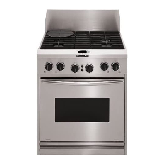
- Page 1 KAC-29 TECHNICAL EDUCATION PROFESSIONAL DUAL FUEL RANGE WITH SELF-CLEAN THERMAL CONVECTION OVEN JOB AID 4317282...
- Page 2 FORWARD This Job Aid, “Professional Dual Fuel Range With Self-Clean Thermal Convection Oven,” (Part No. 4317282), provides the technician with information on the operation and service of the Pro- fessional Dual Fuel Range. It is to be used as a training Job Aid and Service Manual. The wiring diagrams and strip circuits used in this Job Aid are typical and should be used for training purposes only.
-
Page 3: Table Of Contents
Table of Contents Page SPECIFICATIONS ........................1-1 COMPONENT ACCESS ......................2-1 Component Locations ......................2-1 Removing A Sealed Burner & Ignitor ................. 2-2 Removing The Control Power And Lamp Transformers, The Electronic Range Control, The Oven Door Latch Assembly, & Spark Module ........ 2-4 Removing The Front Panel, Display, Selector &... - Page 4 INTERNATIONAL SALES IND. X = OXFORD or MARKETING CHANNEL IF PRESENT YEAR OF MANUFACTURE K = 2000 K = KITCHENAID BRAND WEEK OF MANUFACTURE PRODUCT IDENTIFICATION DD = DUAL FUEL DROP-IN / SLIDE-IN PRODUCT SEQUENCE NUMBER DR = DUAL FUEL RANGE...
- Page 5 MODEL & SERIAL NUMBER LABEL AND TECH SHEET LOCATIONS The Model/Serial Number label and Tech Sheet locations are shown below. NOTE: The tech sheet is accessible by removing the cooktop. To remove the cooktop, refer to page 2-2 for the procedure.
- Page 6 IMPORTANT SAFETY INFORMATION Your safety and the safety of others is very important. Important safety messages have been provided in this Job Aid. Always read and obey all safety messages. This is the safety alert symbol. This symbol alerts you to hazards that can kill or hurt you and others. All safety messages will be preceded by the safety alert symbol and the word “WARNING.”...
-
Page 7: Specifications
SPECIFICATIONS SIZE 30" NEW MODEL NUMBER KDRP407HSS Controls Push-To-Turn Yes -4 Infinite Yes - 4 Location Front/Vertical Ignition System Electronic-Lite Position Knobs Black-KA design-heavy duty Control Panel Color Stainless Landing Ledge Stainless-KA design Oven "On" Light Oven Clean Light Hot Surface Indicators Burners Sealed Yes-4... - Page 8 Specifications (continued) SIZE 30" NEW MODEL NUMBER KDRP407HSS Other Upper Oven Features Oven Cleaning System Self Clean Auto Self Clean Latch Hidden Bake Element Bake Element 2000w @ 240V 1500w @ 208V Broil Element 2667w @ 240V 2000w @ 208V Convection Element 1600w @ 240V 1200w @ 208V...
-
Page 9: Component Access
COMPONENT ACCESS This section instructs you on how to service each component inside the range. The components and their locations are shown below. COMPONENT LOCATIONS Oven Temperature Sensor Lamp Transformer Suppressor (Mounted On Terminal Block L1 & Neutral) Electronic Control Power Transformer Range Control Display Spark Module... -
Page 10: Removing A Sealed Burner & Ignitor
REMOVING A SEALED BURNER & IGNITOR Use a T20 torx screwdriver and remove WARNING the two screws from each burner head, then lift the heads off the cooktop. ELECTRICAL SHOCK HAZARD Sealed Ignitor Burner Head Burner Disconnect power before servicing the range. Replace all panels before operating range. - Page 11 To remove a sealed burner: c) Remove the two hex-head screws from the burner bracket and remove the a) Disconnect the ignitor wire from the sealed burner. ignitor terminal (see step 5). d) Remove the screw from the ignitor b) Use a 1/2˝ open-end or an adjustable bracket and remove the ignitor from the wrench and remove the gas line fitting sealed burner.
-
Page 12: Removing The Control Power And Lamp Transformers, The Electronic Range Control, The Oven Door Latch Assembly, & Spark Module
REMOVING THE CONTROL POWER AND LAMP TRANSFORMERS, THE ELECTRONIC RANGE CONTROL, THE OVEN DOOR LATCH ASSEMBLY, & SPARK MODULE Starting from the front, peel off the rubber WARNING tape from around the top access panel. NOTE: Carefully peel the tape off as one continuous piece, and do not allow the ELECTRICAL SHOCK HAZARD adhesive sections to stick together. - Page 13 The top access panel components described To remove the lamp transformer: on this page are shown below. a) Remove the screw from the mounting bracket tab and slide the other bracket Lamp Control Power tab out of the chassis slot. Transformer Transformer b) Disconnect the 2 white and 2 black...
- Page 14 The oven door latch assembly location is shown b) Remove the four screws from the front below. and top of the assembly (2 at each location). Oven Door Latch Oven Door Latch Assembly Assembly Front Screws Oven Door Latch Assembly Top Screws To remove the oven door latch assem- bly:...
- Page 15 The spark module is mounted to the right side 10. To remove the spark module: of the range just below the front corner of the a) Disconnect the wires from the termi- chassis, as shown in the dashed line area nals.
-
Page 16: Removing The Front Panel, Display, Selector & Set Controls, Gas Valve, & Ignition Switches
REMOVING THE FRONT PANEL, DISPLAY, SELECTOR & SET CONTROLS, GAS VALVE, & IGNITION SWITCHES b) Open the oven door and remove the WARNING two bottom end front panel screws. ELECTRICAL SHOCK HAZARD Disconnect power before servicing the range. Replace all panels before operating range. Failure to do so can result in death or electri- cal shock. - Page 17 To remove the display: e) Disconnect the 16-wire cable at the selector and set control assembly board a) Remove the front panel (see step 3 on connector JP01. the previous page). f) Unclip the display board from the plas- b) Remove the two display screws from tic holder.
- Page 18 To remove the selector and set control f) Disconnect the 2-wire cable from the assembly: electronic range control board connec- tor JP40. a) Remove the cooktop (see page 2-2). g) Disconnect the 16-wire cable from the b) Remove the top access panel (see electronic range control board connec- page 2-4).
- Page 19 To remove a gas valve: d) Remove the gas line from the gas valve. a) If not already done, remove the front panel (see step 3 on page 2-8). Gas Line b) Remove the rubber shield from the gas valve stem. Manifold Rubber Gas Valve...
- Page 20 To remove the ignition switches: d) Disconnect the ignition switch wires from the harness connector and the NOTE: The ignition switches must be replaced spark module terminal. as an assembly. They cannot be changed individually. e) Remove the plastic grommet and pull the ignition switch wire connectors a) If not already done, remove the cooktop through the chassis hole.
-
Page 21: Removing A Halogen Lamp Assembly
REMOVING A HALOGEN LAMP ASSEMBLY Pull the halogen bulb out of the socket. WARNING ELECTRICAL SHOCK HAZARD Halogen Bulb Disconnect power before servicing the range. Replace all panels before operating range. Failure to do so can result in death or electri- cal shock. -
Page 22: Removing The Broil Element
REMOVING THE BROIL ELEMENT Remove the two front bracket screws and WARNING two rear bracket screws from the broil element. ELECTRICAL SHOCK HAZARD Front Bracket Screws Disconnect power before servicing the range. Replace all panels before operating range. Failure to do so can result in death or electri- Broil cal shock. -
Page 23: Removing The Oven Temperature Sensor
REMOVING THE OVEN TEMPERATURE SENSOR Turn off the gas and electrical power going WARNING to the range. Remove the racks from inside the oven. ELECTRICAL SHOCK HAZARD Remove the two mounting screws from the oven temperature sensor and pull the Disconnect power before servicing the range. -
Page 24: Removing The Gas Regulator
REMOVING THE GAS REGULATOR Remove the two screws from the bottom WARNING trim strip. Lower the trim strip so it is free of the slots in the sides of the oven, and remove the strip. ELECTRICAL SHOCK HAZARD Disconnect power before servicing the range. Replace all panels before operating range. -
Page 25: Removing The Rear Panel
REMOVING THE REAR PANEL Remove the two screws from the top and WARNING bottom braces and remove the braces from the range. ELECTRICAL SHOCK HAZARD Disconnect power before servicing the range. Replace all panels before operating range. Screws 2 of 4 Failure to do so can result in death or electri- cal shock. -
Page 26: Removing The Convection Bake Element & Fan Motor Assembly
REMOVING THE CONVECTION BAKE ELEMENT & FAN MOTOR ASSEMBLY To remove the convection bake ele- WARNING ment: a) Remove the two screws from the con- ELECTRICAL SHOCK HAZARD vection bake element. b) Pull it forward so you can access the Disconnect power before servicing the range. - Page 27 To remove the convection fan motor: f) Remove the two convection fan motor mounting screws and remove the mo- a) If not already done, remove the con- tor from the rear of the range. vection cover and the convection bake element from the rear of the oven liner Convection Fan Motor (see page 2-18).
-
Page 28: Removing The Blower Motor Assembly
REMOVING THE BLOWER MOTOR ASSEMBLY Remove the four screws from the blower WARNING motor assembly cover and remove the cover from the range. ELECTRICAL SHOCK HAZARD Screw 1 of 4 Disconnect power before servicing the range. Replace all panels before operating range. Failure to do so can result in death or electri- cal shock. -
Page 29: Removing The Suppressor Board
REMOVING THE SUPPRESSOR BOARD Remove the blower motor assembly cover WARNING (see page 2-20). Remove the two screws from the suppres- ELECTRICAL SHOCK HAZARD sor board. Disconnect the wires from the terminals Disconnect power before servicing the range. and remove the board from the range. Replace all panels before operating range. -
Page 30: Removing The Oven Shutdown Thermal Fuse
REMOVING THE OVEN SHUTDOWN THERMAL FUSE Remove the two screws from the oven WARNING shutdown thermal fuse and remove the fuse from the rear of the range. ELECTRICAL SHOCK HAZARD Oven Shutdown Thermal Fuse Disconnect power before servicing the range. Replace all panels before operating range. -
Page 31: Removing The Hidden Bake Element
REMOVING THE HIDDEN BAKE ELEMENT Remove the four screws from the hidden WARNING bake element cover flanges. Cover Flange Cover Flange ELECTRICAL SHOCK HAZARD & 2 Screws & 2 Screws Disconnect power before servicing the range. Replace all panels before operating range. Failure to do so can result in death or electri- cal shock. - Page 32 Carefully move the upper and lower sec- Carefully pull the hidden bake element tions of the insulation blanket out of the and its mounting bracket out of the range. way so that you can access the hidden bake element and its mounting bracket. Remove the four mounting bracket screws and the two hidden bake element bracket screws.
-
Page 33: Removing The Oven Door
REMOVING THE OVEN DOOR Close the oven door as far as the two pins WARNING will allow. Grasp the sides of the door and lift the door ELECTRICAL SHOCK HAZARD until it stops, then pull the hinge hangers out of the slots. Disconnect power before servicing the range. -
Page 34: Removing The Oven Door Glass, Hinges, & Handle
REMOVING THE OVEN DOOR GLASS, HINGES, & HANDLE To remove the outer door glass: WARNING a) Remove the three outer glass holder screws and two outer glass bracket ELECTRICAL SHOCK HAZARD screws from the door liner. Disconnect power before servicing the range. b) Lift the outer glass with the glass holder off the door liner. - Page 35 To remove the hinges and the inner d) Remove the insulation and the inner door glass: door glass. NOTE: You will have to remove both hinges to remove the inner door glass from the oven door liner. a) Lift either side of the door liner, remove Inner Door Glass the two door hinge screws, and remove the hinge.
-
Page 36: Removing The Oven Door Gasket
REMOVING THE OVEN DOOR GASKET Open the oven door to its fully open posi- WARNING tion. Remove the screw from the door gasket ELECTRICAL SHOCK HAZARD bracket and remove the bracket from the range. Disconnect power before servicing the range. Replace all panels before operating range. -
Page 37: Component Testing
COMPONENT TESTING Before testing any of the components, perform • Check all of the connections before you the following checks: replace the components. Look for broken, or loose wires, failed terminals, or wires that • The most common cause for control failure is are not pushed firmly onto their connectors. -
Page 38: Control Power & Lamp Transformers
CONTROL POWER & LAMP TRANSFORMERS WARNING LOAD (SECONDARY) Electrical Shock Hazard Disconnect the electrical supply from the unit before servicing. Failure to do so could result in death or electrical shock. TEST PROCEDURE LINE (PRIMARY) Refer to page 2-4 for the procedure for servic- ing the control power and lamp transformers. -
Page 39: Blower Motor
BLOWER MOTOR WARNING Electrical Shock Hazard Disconnect the electrical supply from the unit before servicing. Failure to do so could result in death or electrical shock. TEST PROCEDURE Refer to page 2-20 for the procedure for ser- vicing the blower motor. Motor Disconnect power from the range. -
Page 40: Oven Door Latch Assembly
OVEN DOOR LATCH ASSEMBLY WARNING Solenoid Latch Switch Electrical Shock Hazard Door Switch Disconnect the electrical supply from the unit before servicing. Failure to do so could result in death or electrical shock. TEST PROCEDURE Refer to page 2-6 for the procedure for servic- ing the oven door latch assembly. -
Page 41: Oven Temperature Sensor
OVEN TEMPERATURE SENSOR WARNING Oven Temperature Sensor Electrical Shock Hazard Disconnect the electrical supply from the Connector unit before servicing. Failure to do so could result in death or electrical shock. TEST PROCEDURE Resistance Test (At The Electronic Refer to page 2-15 for the procedure for ser- Range Control) vicing the oven temperature sensor. -
Page 42: Oven Shutdown Thermal Fuse
OVEN SHUTDOWN THERMAL FUSE WARNING Electrical Shock Hazard Disconnect the electrical supply from the unit before servicing. Failure to do so could result in death or electrical shock. TEST PROCEDURE Refer to page 2-22 for the procedure for ser- Resistance Test (At The Electronic vicing the oven shutdown thermal fuse. -
Page 43: Convection Bake Element
CONVECTION BAKE ELEMENT WARNING Electrical Shock Hazard Disconnect the electrical supply from the unit before servicing. Failure to do so could result in death or electrical shock. TEST PROCEDURE Refer to page 2-18 for the procedure for ser- Resistance Test (At The Electronic vicing the convection bake element. -
Page 44: Convection Fan Motor
CONVECTION FAN MOTOR WARNING Electrical Shock Hazard Disconnect the electrical supply from the unit before servicing. Failure to do so could result in death or electrical shock. TEST PROCEDURE Terminals Refer to page 2-18 for the procedure for ser- vicing the convection fan motor. Resistance Test (At The Electronic Disconnect power from the range. -
Page 45: Broil Element
BROIL ELEMENT WARNING Electrical Shock Hazard Disconnect the electrical supply from the unit before servicing. Failure to do so could result in death or electrical shock. TEST PROCEDURE Refer to page 2-14 for the procedure for ser- Resistance Test (At The Electronic vicing the broil element. -
Page 46: Hidden Bake Element
HIDDEN BAKE ELEMENT WARNING Electrical Shock Hazard Disconnect the electrical supply from the unit before servicing. Failure to do so could result in death or electrical shock. TEST PROCEDURE Refer to page 2-23 for the procedure for ser- vicing the hidden bake element. Resistance Test (At The Electronic Disconnect power from the range. -
Page 47: Ignition Switches
IGNITION SWITCHES Ignition Switch Wire WARNING Connector At Spark Module Electrical Shock Hazard Disconnect the electrical supply from the unit before servicing. Failure to do so could result in death or electrical shock. TEST PROCEDURE Refer to page 2-12 for the procedure for ser- vicing the ignition switches. - Page 48 — NOTES — 3-12...
-
Page 49: Diagnosis & Troubleshooting
DIAGNOSIS & TROUBLESHOOTING NOTES: All ranges that fail within the first few days should be checked for loose connections When diagnosing this dual fuel range, or miswiring. always begin by checking for the correct line voltage, blown fuses, and failed com- All voltage and resistance checks should ponents. -
Page 50: Electronic Range Control Pinouts
ELECTRONIC RANGE CONTROL PINOUTS FUNCTION COLOR P1-1 Blower Gray P1-2 – P1-3 Convection Fan Motor Orange P1-4 – P1-5 Halogen Light Black P3-1 Earth Ground Green P3-2 Control Power Transformer Secondary Blue P3-3 Control Power Transformer Secondary Blue P3-4 – P3-5 –... -
Page 51: Electronic Range Control Component Test Points
ELECTRONIC RANGE CONTROL COMPONENT TEST POINTS COMPONENTS FRONT/REAR CHECK POINTS RESULTS Door Switch P7-1 (green) to P7-3 (tan) Door Open = Closed Circuit Door Closed = Open Circuit 50 Ω Door Lock Solenoid P6-1 (white) to P6-2 (yellow) (with door closed) 1080 Ω... - Page 52 — NOTES —...
-
Page 53: Wiring Diagrams & Strip Circuits
WIRING DIAGRAMS & STRIP CIRCUITS OVEN WIRING DIAGRAM CONTROL POWER TRANSFORMER SUPPRESSOR WP#4451985 P3-3 P3-2 P4-1 P6-1 P4-3 LATCH DRIVE CIRCUIT P9-1 P6-2 WISP CONNECTORS 18 VDC P9-3 SOLENOID DOOR LOCK ELECTRONIC RANGE SOLENOID CONTROL CONV-1600W P5-1 P7-4 TEMP SENSOR 1080 Ω... -
Page 54: Strip Circuits
STRIP CIRCUITS PREHEAT BAKE / BAKE BAKE-2000W P5-2 BROIL-3000W P4-1 P5-5 P4-3 DOUBLE LINE BREAK RELAY P1-1 LAMP TRANSFORMER BLOWER P1-5 HALOGEN 5W/BULB BROIL BROIL - 3000W P5-5 DOUBLE LINE P4-1 BREAK RELAY BLOWER P1-1 P4-3 LAMP TRANSFORMER P1-5 HALOGEN 5W/BULB KEEP WARM BAKE - 2000W... - Page 55 BREAD NOT ENERGIZED DURING PREHEAT CONV - 1600W P5-1 BAKE - 2000W P4-1 P5-2 P4-3 BROIL - 3000W P5-5 DOUBLE LINE BREAK RELAY BLOWER P1-1 CONV. FAN P1-3 LAMP TRANSFORMER P1-5 HALOGEN 5W /BULB PROOF BROIL-3000W P5-5 P4-1 DOUBLE LINE P4-3 BREAK RELAY CLEAN...
- Page 56 CONVECTION BAKE CONV.-1600W P5-1 P4-1 BAKE-2000W P5-2 P4-3 DOUBLE LINE BREAK RELAY BLOWER P1-1 CONV. FAN MOTOR P1-3 LAMP TRANSFORMER P1-5 HALOGEN 5W/BULB CONVECTION BROIL BAKE-2000W P5-5 P4-1 DOUBLE LINE BREAK RELAY BLOWER P4-3 P1-1 CONV. FAN MOTOR P1-3 LAMP TRANSFORMER P1-5 HALOGEN 5W/BULB...
-
Page 57: Tech Tips
These parts will fit right and work Call the KitchenAid Consumer Assistance Cen- right, because they are made with the same ter toll free, at precision used to build every new KitchenAid 1-800-422-1230 appliance. If you need assistance or service in Canada:... -
Page 58: Dual Fuel Range Warranty
G. Replacement parts or repair labor costs for units operated outside the United States and Canada. KITCHENAID AND INGLIS LIMITED SHALL NOT BE LIABLE FOR INCIDENTAL OR CONSE- QUENTIAL DAMAGES. Some states or provinces do not allow the exclusion or limitation of incidental or consequential damages, so this exclusion or limitation may not apply to you. - Page 59 CORPORATION...